Transcription
THROUGHPUT TEST METHODS FOR MIMO RADIOSAchieving high throughput and repeatable resultsBy Fanny Mlinarsky1/14/2014ABSTRACT: This paper discusses the challenges and methods of achievingmaximum MIMO throughput and repeatable measurements over a widedynamic range and under a variety of wireless channel conditions. It focuses onMIMO over the air (OTA) test methods.Rev. B 1/2014
THROUGHPUT TEST METHODS FOR MIMO RADIOSAchieving high throughput and repeatable resultsAs many engineers know, getting repeatable and consistent measurements, particularly when testingMIMO devices, is next to impossible. The reasons?1. Modern wireless devices are designed to automatically adapt to the changing channel conditions.2. Wireless environment constantly changes vs. time, frequency and radio motion. The timevariability of path loss, multipath, Doppler effects and interference often baffles the decisionmaking logic of the adaptation algorithms.3. Adaptation algorithms are complex and sometimes get into unintended states.Modern radios can change their data rate from 1 Mbps to over 1 Gbps on a packet-by-packet basis inresponse to impairments, such as signal fades or interference [13].In addition to data rate adaptation, MIMO radios are adaptable in terms of their MIMO mode of operation.A few representative MIMO modes are explained in Table 1.Table 1: MIMO modes of transmissionMIMO ModeSpatialMultiplexing (SM)TX diversityRX diversityCombination of TXand RX diversityBeamformingMulti-user MIMO(MU-MIMO)ExplanationUse of MIMO radios to transmit two or more spatial streams in the samefrequency channel.Use of MIMO radios to transmit slightly different versions of the same signalin order to optimize reception of at least one of these versions. TX diversityschemes include space time block coding (STBC), space frequency blockcoding (SFBC) and cyclic delay diversity (CDD).Use of MIMO radios to combine multiple received versions of the same signalin order to minimize PER. A common RX diversity technique is maximal ratiocombining (MRC).Use of TX diversity at the transmitting device in combination with RX diversityat the receiving device.Use of MIMO transmitters to create a focused beam, thereby extending therange of the link or enabling SM.Forming multiple focused beams or using TX diversity techniques to enablesimultaneous communications with multiple device. Typically beamforming isdone by a base station or an access point (AP) to communicate simultaneouslywith multiple client devices.Commercial wireless chipsets typically support a subset of the MIMO modes outlined in Table 1 and someimplement other proprietary modes. In the fast-changing wireless environment and with real-timedecision making process, wireless devices sometimes exhibit flaws in their adaptation algorithms.Adaptation issues can severely impact throughput, but can be difficult to identify and track in the changingreal-life environment.Later in this paper we will discuss the benefits of controlled environment testbeds. But first, let’s examinehow MIMO radios work.OCTOSCOPE WHITE PAPER1
THROUGHPUT TEST METHODS FOR MIMO RADIOSAchieving high throughput and repeatable resultsWhat factors impact MIMO throughput?Many factors associated with the wireless channel and DUT antennas impact MIMO throughput. Theseinclude MIMO channel correlation, DUT antenna spacing, motion of the DUTs and reflectors, multipathreflections, interference and other factors. Table 2 summarizes and explains these factors.Table 2: Factors that impact MIMO throughputFactorsExplanation/ImpactNotesMIMO channelcorrelationFunction of severalvariables including deviceantenna spacing, antennapolarization and multipathRelated to correlation andstrongly influenced bymultipath in the channelThe lower the correlation the higher thethroughputAngular spread of thereceived signalDevice antenna spacingand device orientationRelated to angular spreadand correlationAntenna polarizationVertical, horizontal orcircularNoise and interferenceHigh noise power withrespect to signal powerresults in low SNR (signalto noise ratio) conditions.The term SINR (signal tointerference noise ratio)is also sometimes used.Causes Doppler spread ofthe signalMotion of devices ormultipath reflectorsDelay spread ofreflectionsCauses clusters ofreflections to arrive at thereceiver at different timesMultipath causes signal to bounce aroundand arrive at different angles, therebywidening the angular spread at a receiver.Typically, the wider the angular spreadthe higher the MIMO throughput.MIMO throughput will vary vs. deviceorientation and antenna spacing.Typically, the wider the antenna spacingthe lower the correlation and the higherthe throughput.Cross-polarization (e.g. both vertical andhorizontal) is sometimes used to lowerMIMO correlation, thus enabling spatialmultiplexing. Multipath reflections canalter polarization.MIMO devices can adapt to theenvironment by selecting the mostsuitable mode of operation (e.g. TXdiversity in low SNR conditions; spatialmultiplexing in high SNR, low correlationconditions).OFDM signaling is sensitive to Dopplerspread. Throughput should be measuredin a variety of Doppler environments.Delay spread is higher for larger spaces(e.g. outdoors) than for smaller spaces(e.g. home environment)When considering a controlled environment wireless testbed, Table 2 should serve as a guide. The testbedshould be able to configure in a reproducible manner the conditions listed in Table 2. Furthermore, thetestbed should be able to create an optimum environment that brings about maximum throughput andrange of any device under test (DUT). The latter is important for benchmarking.OCTOSCOPE WHITE PAPER2
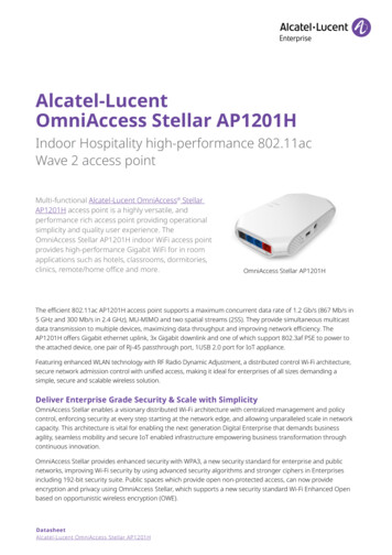
THROUGHPUT TEST METHODS FOR MIMO RADIOSAchieving high throughput and repeatable resultsWhat are the requirements for a laboratory based wireless testbed?A laboratory based wireless testbed has to offer an environment that:1. Creates conditions under which throughput of the DUT is maximized2. Emulates a range of realistic conditions, including path loss, multipath, noise and interference3. Guarantees repeatable measurements reproducible at labs around the world; metrics to includethroughput, packet error rate (PER) and range of the DUT - with and without channel impairmentsThe present day challenge for the industry is to create a wireless testbed that accommodates all 3 of theabove criteria while supporting multiple input multiple output (MIMO) transmission over the air (OTA) totest the latest LTE-Advanced and IEEE 802.11n/ac devices.Legacy single input single output (SISO) devices typically contain a single radio and often have externalantennas. Historically, legacy radios have been tested via aconducted connection to their antenna ports (Figure 1, left).New generationwireless testbeds mustNew generation smartphones, access points (APs), base stations,support MIMO OTApads and sensors have multiple radios (e.g. cellular, Wi-Fi,testing toBluetooth, GPS) and often have only internal antennas, makingaccommodate MIMOconducted connections difficult. Thus, new generation wirelessand multi-radio devicestestbeds must support both conducted and OTA coupling and bewith internal antennas.able to test MIMO capable devices over the air.Figure 1: SISO conducted (left) vs. MIMO OTA (right) test configurations. DUT and partner (master)devices are is placed into isolation chambers and coupled to one another to create a test link.OCTOSCOPE WHITE PAPER3
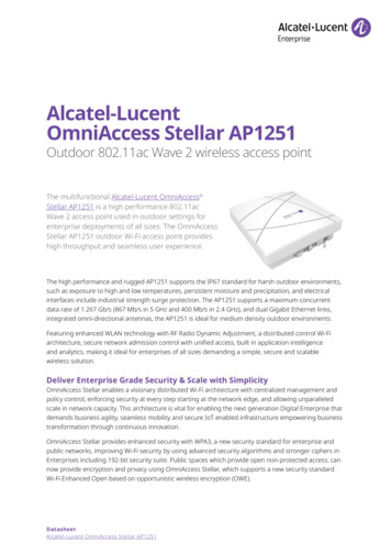
THROUGHPUT TEST METHODS FOR MIMO RADIOSAchieving high throughput and repeatable resultsWhat’s the best way to set up realistic MIMO channel environment for repeatable radio testing?Engineers testing MIMO radios need to create a range of channel conditions in order to validate the radios’adaptability and throughput performance. This can be accomplished using a MIMO channel emulator(fader) or an octoScope multipath emulator, MPE [1]. A fader or an MPE can interconnect two or moredevices via cabling to the device antenna ports or over the air. Fordevices such as smartphones, pads or sensors with difficult-to-reachinternal antennas OTA coupling is highly desirable.The shape of theWhen testing devices with internal antennas, device orientation withantenna field variesrespect to the test antennas can have a significant impact on thefrom product tomeasured throughput. The reason is that the radiated field ofproduct and test resultsinternal antennas can be non-uniform, as shown in Figure 3 on thevary vs. DUTright. The field of an internal antenna may have nulls and peaksorientation withbecause the antennas are sometimes blocked by batteries, PC boardrespect to the testground planes and other metal surfaces of the device.antennas.Figure 3: Antenna field example. CST Microwave Studio simulation of a dipole antenna field (left) andthe same antenna simulated inside a Wi-Fi device (right). The red areas represent high antenna gain(see scale on top). DUT orientation with respect to test antennas impacts the signal power coupled OTA.When testing over the air, engineers sometimes rotate the device and measure performance in 4orientations: 0, 90, 180 and 270 degrees with respect to the test antennas. The 0 degree orientation isarbitrary and simply represents the starting orientation.OCTOSCOPE WHITE PAPER4
THROUGHPUT TEST METHODS FOR MIMO RADIOSAchieving high throughput and repeatable resultsMIMO test antennasDUT should be rotated withrespect to test antennas andmeasurements averagedModel of anantenna fieldFigure 4: Because antenna field of the DUT is typically characterized by peaks and nulls, engineerssometimes measure throughput at different orientations of the DUT with respect to test antennas.With MIMO devices, multiple antennas operate simultaneously, forming a multi-beam field. For devicessuch as APs, manufacturers typically try to have the MIMO antenna field be uniform around the azimuthal(horizontal) plane. For devices such as phones, the field may be specifically designed to point in onedirection, for example upwards towards a base station.How do device antennas impact MIMO throughput?One aspect of MIMO radio technology is the use multiple antennas to minimize nulls in the combinedmulti-antenna field. This is done by spacing the MIMO antennas far enough away from one another andat a distance equal to a multiple of the signal ¼ wavelength. In a multipath environment, some reflectionsof the radiated signal can arrive vertically polarized and some horizontally polarizes. For this reason,sometimes device manufacturers cross-polarize the antennas (e.g. 2 antennas vertically polarized and 2antennas horizontally polarized). Cross-polarization of device antennas also helps reduce MIMOcorrelation and thus increase the theoretical capacity of a MIMO channel.To maximize MIMO throughput of omnidirectional devices, such as Wi-Fi APs, manufacturers ‘point’ theMIMO antennas in all directions in order to couple the signal that’s reflected from all directions. Andwhen the antennas are pointed in all directions, the maximum MIMO throughput is achieved when theOCTOSCOPE WHITE PAPER5
THROUGHPUT TEST METHODS FOR MIMO RADIOSAchieving high throughput and repeatable resultssignal arrives from all directions, typically due to multipath. Hencemultipath helps increase throughput in typical Wi-Fi networks.Multipath typically widens the angular spread of the signal at thereceiving device by virtue of reflections from opposing surfaces,thus reducing MIMO correlation of the channel and increasingMIMO throughput.The wider the MIMO antenna spacing, the wider the angular spreadof the signal, the lower the MIMO correlation and the higher thethroughput. In a small handset where there is no room to spaceapart the antennas, correlation may be high, causing MIMO gainsin throughput to be so low as to offer little benefit over theconventional SISO technology.Multipath typicallywidens the angularspread of the signal atthe receiving device byvirtue of reflectionsfrom opposing surfaces,thus reducing MIMOcorrelation of thechannel and increasingMIMO throughput.Delay spread of multipath reflectionsIn addition to angular spread of the signal, in the real-world environment we also have delay spread.Delay spread is the difference between the longest and shortest delays of the reflections and is statisticalin nature. Radios are designed to operate with a certain range of multipath delay spread, which can belonger outdoors and shorter indoors. Cyclic prefix (CP) or guard interval (GI) in the OFDM symbol mustbe of sufficient duration to allow multipath reflections to settle prior to decoding the symbol.To help engineers optimize radio design for specific environments (e.g. phones for outdoors, APs forindoors), the wireless industry has developed a few standard channel models for indoor and outdoorspaces. Commercial faders implement IEEE and 3GPP models [4-12] to enable radio testing in a range ofstandards-based emulated environments.A summary of IEEE 802.11n indoor channel models [4] is shown in Table 3.Table 3: IEEE 802.11n standard channel modelsModelA*BCDEFtest modelResidentialsmall officetypical officelarge officelarge spaceDistance to 1st wall(avg)#tapsDelay spread(rms)Maxdelay#clusters5m5m10 m20 m30 m19141818180 ns15 ns30 ns50 ns100 ns150 ns0 ns80 ns200 ns390 ns730 ns1050 ns22346* Model A is a flat fading model; no delay spread and no multipathOCTOSCOPE WHITE PAPER6
THROUGHPUT TEST METHODS FOR MIMO RADIOSAchieving high throughput and repeatable resultsNotice how delay and delay spread in Table 3 increase as larger spaces are being modeled by the IEEEmodels A through F. IEEE 802.11n/ac channel models [4-5] are defined in terms of ‘clusters’ of multipathreflections. A cluster is a group of rays reflecting together from, for example, a corner of a room or a walland propagating as a group. The IEEE Model B, modeling a house, has 2 clusters. Model D, modeling alarger space, has 3 clusters. Figure 5 demonstrates the concept of clusters.Figure 5: Multipath reflectionstravel in clusters and arrive at thereceiving device as multiple clustersof energy spaced in time.Reflectors can be mobile (e.g. avehicle). Moving reflectors ormoving radios introduce a Dopplershift to the signal.A cluster typically arrives at the receiver multiple times as it bounces back and forth between oppositesurfaces, as shown in Figure 6. Each time the cluster arrives at the receiver its power is lower. Multipleclusters can overlap in time, creating what’s called a Power Delay Profile (PDP) of the signal at the receiver.Figure 6 shows the 3-cluster PDP of Model D.Figure 6: IEEEModel D 3cluster PDP.Each clusterbounces backand forth,monotonicallydiminishing inpower with eachbounce. Multipleclusters overlapin time and addtogether to formPDP.Source of PDPplot: [4].OCTOSCOPE WHITE PAPER7
THROUGHPUT TEST METHODS FOR MIMO RADIOSAchieving high throughput and repeatable resultsFaders typically model angular spread, PDP, Doppler shift, SNR and other channel impairments. Becauseconventional faders are designed to connect to the DUT via conducted connections, they also modelMIMO antenna arrays and correlation in the wireless channel. New OTA models are becoming availablefor MIMO faders for use in the emerging MIMO OTA testbeds [11-12].When selecting a fader, make sure that it offers OTA support. Traditional channel models incorporate themodeling of MIMO antenna arrays, which makes them unsuitable for use with real test antennas.Is it possible to maximize MIMO OTA throughput in a small anechoic chamber?Device manufacturers want MIMO OTA testbeds that can demonstrate the upper limit of their product’sperformance consistently, repeatably and at multiple locations around the world.To maximize MIMO OTA throughput we need to create a multipath environment, making sure that:1. The signal arrives at the MIMO DUT with a wide angular spread (i.e. from all directions)2. Multipath reflections conform to industry standard PDPs in terms of delay spread3. The testbed guarantees repeatable resultsAs an example, let’s take a look at the octoBoxTM wireless testbed. octoBox is a small anechoic chamberlined with gradient absorber.Figure 7: Gradient absorber is composed of layers of monotonically increasing impedance, matchingthe low impedance of the metal surfaces of octoBox to the high impedance of air.The absorber guarantees 20 dB of damping on any reflections from the walls, floor and ceiling of thechamber in the frequency range of 1 to 6 GHz and 15 dB damping down to 700 MHz, which is a realisticmagnitude of reflections in a typical house. With reflections surrounding the DUT from walls, ceiling andfloor of octoBox, we create a wide-angular-spread environment modeling non-line-of-sight (NLOS)multipath reflections to help achieve maximum throughput.The direct line of sight (LOS) transmission between the test antennas and the DUT is also set up to have awide angular spread, which is a function of the proximity of test antennas to the DUT, as demonstrated inFigure 8.OCTOSCOPE WHITE PAPER8
THROUGHPUT TEST METHODS FOR MIMO RADIOSAchieving high throughput and repeatable resultsFigure 8: Narrower angular spread due to longer distance to the test antenna array (left); widerangular spread resulting from proximity to the test antenna array (right).Antenna spacing inside octoBox is adjustable and set at the factory to resemble an antenna array of a realMIMO device (e.g. a MIMO AP), as shown in Figure 9.Figure 9: Example of MIMO test antenna arrangement inside octoBox small anechoic chamber. The MIMOantennas are spaced approximately the same way as they would be on an access point. All corner bracketsand antenna rails are made of non-reflective plastic.But how do we achieve a long enough multipath delay spread in a small box to render multipath realistic?In real life delay spread depends on the physical space. It is shorter for small rooms and longer for largerrooms or outdoor spaces. Conventional faders emulate both delay spread and angular spread of a wirelesschannel. These instruments perform emulation computationally on a digitized signal, which results incomplex and expensive solutions [15]. Taking a simpler and closer-to-reality approach, octoBox MPE(multi path emulator) emulates realistic delay spread of multipath reflections by bouncing the signal offthe ends of precisely tuned RF cables.OCTOSCOPE WHITE PAPER9
THROUGHPUT TEST METHODS FOR MIMO RADIOSAchieving high throughput and repeatable resultsWhat is octoBox MPE testbed?octoBox MPE testbed, shown in Figure 10, consists of 2 octoBox chambers and an MPE module stackedbetween the chambers. MPE creates multipath that conforms to the IEEE standard PDP on multiple MIMOpaths. The MIMO paths couple to the MIMO antenna array located in the top chamber together with theDUT.Figure 10: octoBox MPE testbed for MIMO OTA measurements. Left: block diagram; right: photoProgrammable RF attenuators in-line with each MIMO path introduce flat path loss, modeling lossesthrough walls or air. The MPE module models multipath on each of the 4 MIMO paths.To measure throughput or PER, we can use external PCs to transfer traffic. External PCs communicatewith the equipment inside octoBoxes and can be cabled via feed-through Ethernet or USB filters built intooctoBox (more on filters below). The bottom external PC in Figure 10 serves as a remote desktopcontrolling the PC inside the bottom chamber that houses the client adapter. This client is the ‘master’for testing an AP DUT. When testing a client DUT, such as a smartphone, the ‘master’ device wouldtypically be an AP or a base station. A photo of the testbed and a close-up of the bottom box are shownin Figures 11 and 12.OCTOSCOPE WHITE PAPER10
THROUGHPUT TEST METHODS FOR MIMO RADIOSAchieving high throughput and repeatable resultsFigure 11: MPE testbed photo. The bottomchamber houses a ‘master’ device andattenuators. Since the DUT here is an AP, themaster is a client device. If the DUT were aclient (e.g. phone or pad), the master wouldbe an AP or a base station.The top chamber houses the DUT and thetest antennas. The bottom chamber housesthe master and programmable attenuators.The master device is conductively coupled.PC housing 802.11ac clientRF cables to outsideUSB cables toattenuatorsRF cables from client masterAttenuator moduleFigure 12: Close-up view of thebottom octoBox chamber. In thisexample, a PCIe Wi-Fi client deviceis plugged into a mini-tower PC.The client’s antenna ports areconnected via coaxial cables to theattenuators. The opposite ports ofthe attenuators are connected viacoaxial cables to the RF connectorson the side of the octoBox, whichcouple the RF signals outside forconection to the MPE and the topchamber (see block diagram inFigure 10).Why is the master device coupled via conducted connections while the DUT is coupled OTA?In a real life test configuration there is a single OTA link: between the master antennas and the DUTantennas. In the octoBox MPE testbed this OTA link is in the top chamber. If we were to also couple themaster device OTA in the bottom chamber, we would have two points of OTA coupling, which would beinconsistent with real life.OCTOSCOPE WHITE PAPER11
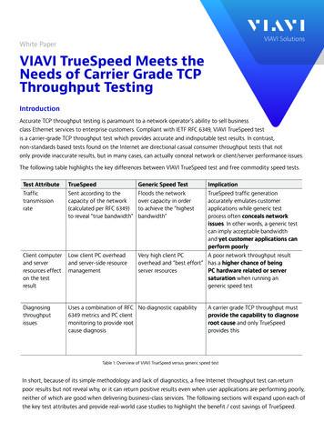
THROUGHPUT TEST METHODS FOR MIMO RADIOSAchieving high throughput and repeatable resultsFigure 13: External interconnections of theoctoBox MPE stack.Double-shielded RF cables are used tointerconnect the programmableattenuators in the bottom chamber to theMPE module and the MPE module to thetest antennas in the upper chamber (seeblock diagram in Figure 10).Extra RF ports can be used to connectmonitor probes, interference sources orother devices into the testbed.SmallNetBuilder (www.smallnetbuilder.com) uses octoBox MPE testbed to evaluate and benchmark theperformance of 802.11 devices.1 SmallNetBuilder has been able to measure inside octoBox top data ratesachievable today by the 802.11ac devices. Using programmable attenuators, SmallNetBuilder is able tocreate plots of throughput vs. path loss, as shown in Figure 14.SmallNetBuilder measures throughput using IxChariotTM software from Ixia. IxChariot supportmeasurements on the TCP/IP or UDP/IP layer. The IP layer throughput is strongly influenced by theIxChariot test file size. SmallNetBuilder uses 2,000,000 to 5,000,000 Byte file size. Higher throughput maybe achievable using IxChariot high performance throughput script, which transmits 10,000,000 Byte vison-7OCTOSCOPE WHITE PAPER12
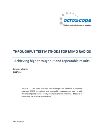
THROUGHPUT TEST METHODS FOR MIMO RADIOSAchieving high throughput and repeatable resultsFigure 14: Example of a throughput vs. attenuation plots produced bywww.smallnetbuilder.comHow does MPE implement industry-standard channel models?octoBox MPE models PDP of each MIMO path per the IEEE 802.11n/ac channel modeling specifications[4-5]. The block diagram of the MPE testbed is essentially the same as that of a conventional fader, butinternal circuitry of the MPE is simpler and closer to real life.Figure 15 shows how well the MPE module matches the PDP of the IEEE Model B. The standard [4] definesPDP for model B in terms of 2 clusters with each cluster being modeled by multiple back-and-forthreflections with each reflection monotonically decreasing in power (see Figure 6 above).OCTOSCOPE WHITE PAPER13
THROUGHPUT TEST METHODS FOR MIMO RADIOSAchieving high throughput and repeatable resultsFigure 15: The measured response of octoBox MPE (shown in blue) closely approximates the IEEE model(shown as green dots for cluster 1 and red dots for cluster 2).OCTOSCOPE WHITE PAPER14
THROUGHPUT TEST METHODS FOR MIMO RADIOSAchieving high throughput and repeatable resultsThe frequency response of the multipath generated by the MPE is shown in Figure 16 and is representativeof typical multipath in the home environment.Figure 16: octoBox MPE frequency response in the 2.4 GHz (top) and 5 GHz (bottom) Wi-Fi bandsOCTOSCOPE WHITE PAPER15
THROUGHPUT TEST METHODS FOR MIMO RADIOSAchieving high throughput and repeatable resultsoctoBox MPE is a broadband device, supporting any channel width, including the widest 802.11ac channelof 160 MHz. Its broadband frequency response is shown in Figure 17.Figure 17: octoBox MPE wideband frequency response from near DC to 6 GHzoctoBox MPE testbed provides realistic RF environment achieved by the carefully arranged anechoicconditions, by the MPE module emulating multipath with a realistic delay spread and by programmableattenuators emulating path loss.The next questions is: How does octoBox MPE testbed guarantee repeatable measurements?OCTOSCOPE WHITE PAPER16
THROUGHPUT TEST METHODS FOR MIMO RADIOSAchieving high throughput and repeatable resultsHow to achieve repeatable measurementsIn today’s connected world, most laboratories and test sites are saturated with interfering wireless traffic.Wireless signals from nearby cellular or Wi-Fi networks can impact the measured throughput at random,making measurements non-repeatable, as shown in Figure 18.Figure 18: Open air throughput measurement varies vs. time due to interference from neighboringwireless networks and devices (top). To make measurements stable and repeatable DUTs are placed intoisolated environment (bottom).Today’s wireless receivers are sensitive down to below -90 dBmand detect even the weakest interfering signals, which can disturbthe test.Screen rooms are often used to protect from externalinterference, but inside a screen room the DUTs and devices in thetestbed still need to be isolated from one another, as shown inFigure 19.Screen rooms are oftenused to protect fromexternal interference,but inside a screenroom the DUTs anddevices in the testbedstill need to be isolatedfrom one another.A DUT placed in the vicinity of a master can often establish a linkand communicate even if its antennas are removed. Under suchcrosstalk conditions, signal level cannot be attenuated below thelevel of crosstalk (Figure 19 bottom left), which can cut the dynamic range by 40-50 dB. This puts alimitation on testing of the adaptation algorithms since the testbed cannot emulate the high path lossconditions (preferably down to -100 dBm) when the link is barely active or broken. To test over the entiredynamic range, devices in the link under test should be isolated from one another by being placed intoindividual isolation chambers, even when they are conductively coupled.OCTOSCOPE WHITE PAPER17
THROUGHPUT TEST METHODS FOR MIMO RADIOSAchieving high throughput and repeatable resultsFigure 19: Example of a conducted test configuration with the DUTs sharing the airlink (left) vs. withisolation between the DUTs provided by isolation chambers (right).Chambers used for OTA testing must have higher isolation than chambers used for conducted testingbecause signal power at the antennas is much stronger than when antennas are replaced with cabledconnections. Most small isolation boxes on the market today are unsuitable for OTA coupling due toinadequate isolation and poor internal absorption.How to select an RF isolation chamberThere are two issues to be aware of when selecting an isolation chamber:1. Isolation specifications can be misleading because they often don’t include the impact of data andpower cables that must penetrate the walls of the chamber to power and control the DUT insideduring the test.2. Most shielded boxes on the market are not designed for OTA coupling. OTA support requires highisolation, absorption and special conditions to enable high MIMO throughput.OCTOSCOPE WHITE PAPER18
THROUGHPUT TEST METHODS FOR MIMO RADIOSAchieving high throughput and repeatable resultsAnother important consideration is maintenance. RF gasketing can wear out after a year of normal use,severely compromising chamber isolation. Gasketing should be easy to replace. Figure 20 shows octoBoxgasketing, which is peel-and-stick and available off the shelf, enabling easy maintenance.Figure 20: octoBox uses peel-and-stick gasketing for easy maintenance. Double gasketing in combinationwith dual door latching mechanism (not shown), creates a perfect seal. Rails and shelf are made of RFtransparent plastic to avoid reflections.Most surfaces inside an anechoic chamber should be either covered with absorber or be made of RFtransparent material, such as plastic or wood to dampen reflections. Reflections cause standing wavesthat result in signal strength fluctuation vs. position of the DUT. For OTA coupling, look for a chamberwith good positional stability. One or two small metal surfaces with no opposing reflectors are OK.Look for a chamber that: Provides feed-through filters for connecting power, Ethernet, USB, HDMI and other interfaces tothe DUT inside the chamber Has sufficient isolation such that the DUT with all data and power cables connected to it throughthe walls of the chamber cannot detect external interference Supports the highest required MIMO data rate over the airOCTOSCOPE WHITE PAPER19
THROUGHPUT TEST METHODS FOR MIMO RADIOSAchieving high throughput and repeatable resultsMost cellular, LTE and Wi-Fi services operate within the 700 MHz to 6 GHz band and this is the band wheredata and power filters must ensure good isolation.Provided the enclosure is well constructed and sealed, data and power filters are typically ‘the weakestlink’ when it comes to isolation. Copper cables can act as antennas picking up signals in the air and carryingthem into and out of the chamber.Data filters must suppress any signals in the operating band of 700 MHz to 6 GHz, so that interferingsignals cannot disturb the test. Filtering is most challenging for data cabling carrying high frequencysignals, such as Ethernet, USB and HDMI. The reason is that the passband of the filter is wide (e.g. 400MHz for USB 2.0) and rejection has to start at the low end of the frequency range (700 MHz), requiring afilter with a steep roll off. Data and power filters must provide at least 60
THROUGHPUT TEST METHODS FOR MIMO RADIOS Achieving high throughput and repeatable results By Fanny Mlinarsky 1/14/2014 Rev. B 1/2014 ABSTRACT: This paper discusses the challenges and methods of achieving maximum MIMO throughput and repeatable measurements over a wide dynamic range and under a variety of wireless channel conditions. .