Transcription
IM-SMA-0673615-03February 2019Installation InstructionsSoffit MountCompact Ceiling Mount Air HandlersElectric or No Heat, with available 5-Speed High Efficiency ECM MotorTABLE OF CONTENTSPAGEPAGEAir Handler Safety .1General & Clearances.2Tools and Parts .2Outdoor Requirements.2Installation .3Refrigerant Line Installation .3Ductwork .3Install Condensate Drain.4Refrigerant Piping .4Electrical Requirements .5Electrical Connections .5Filters .6Refrigerant Charging Instructions .6Thermostat Connections .7Wiring Diagrams .8Electrical Data .8Blower Performance Data .10Air Handler Checks .11Air Handler Maintenance .11Assistance or Service .11Warranty .12AIR HANDLER SAFETYSAFETY CONSIDERATIONSYour safety and the safety of others are very important.We have provided many important safety messages in this manual andon your appliance. Always read and obey all safety messages.This is the safety alert symbol.This symbol alerts you to potential hazards that can kill or hurtyou and others.All safety messages will follow the safety alert symbol and signal word.These signals words mean the following:DANGER: You can be killed or seriously injured if you don’timmediately follow instructions.CAUTION: Indicates a potentially hazardous situation which, if notavoided, may result in minor or moderate injury. Caution may alsobe used to alert against unsafe practices.NOTICE: Indicates a statement of company policy as the messagerelates directly or indirectly to the safety of personnel or protection ofproperty.IMPORTANT: More detailed information concerning the statement ofcompany policy as the message relates directly or indirectly to thesafety of personnel or protection of property.All safety messages will tell you what the potential hazard is, tell you howto reduce the chance of injury, and tell you what can happen if theinstructions are not followed.WARNING: Indicate a potentially hazardous situation which, if notavoided, could result in death or serious injury.Product improvement is a continuous process at Advanced Distributor Products. Therefore, product specifications are subject to change without noticeand without obligation on our part. Please contact your ADP representative or distributor to verify details. by Advanced Distributor Products. All rights reserved.2175 West Park Place Blvd., Stone Mountain, GA 30087www.adpnow.com
GENERAL & CLEARANCESThese instructions are intended as a general guide only and donot supersede any national or local codes in any way.Compliance with all local, state, or national codes pertaining tothis type of equipment should be determined prior toinstallation.WARNINGElectrical ShockDisconnect power before servicing.Read this entire instruction manual, as well as the instructionssupplied in separate equipment, before starting the installation.Replace all parts and panels before operating.All models are designed for indoor installation only.Electrically ground air handler.The installation of the air handler, field wiring, warm air ducts,etc. must conform to the requirements of the National ElectricalCode, ANSI/NFPA No. 70 (latest edition) in the United States,and any state laws, and local ordinances (including plumbingor wastewater codes). Local authorities having jurisdictionshould be consulted before installation is made. Suchapplicable regulations or requirements take precedence overthe general instructions in this manual.Connect ground wire to ground terminal marked “GRD”.Failure to do so can result in death or electrical shock.Explosion HazardKeep flammable materials and vapors,such as gasoline, away from this unit.Place this unit so that the heating elements are at least18in (46cm) above the floor for a garage insulation.This unit is certified for installation clearances to combustiblematerial as listed on the unit rating plate. Accessibility andservice clearances must take precedence over combustiblematerial clearances.Failure to follow these instructions can result in death,explosion or fire.Receiving:IMPORTANTCheck equipment for shipping damage. If you find anydamage, immediately contact the last carrier.The Clean Air Act of 1990 bans the intentional venting ofrefrigerant (CFC’s and HFC’s) as of July 1, 1992. Approvedmethods of reclaiming must be followed. Fines and/orincarceration may be levied for non-compliance.Check the unit rating plate for unit size, electric heat, coil,voltage, phase etc. to be sure unit matches requirements.OUTDOOR SYSTEM REQUIREMENTSThe air handler is designed to match, and must be used with,outdoor units as rated in AHRI. The indoor sections aremanufactured with an interchangeable refrigerant meteringdevice to provide optimum refrigerant control and systemperformance with a variety of different capacities of outdoorunits. In some cases, the AHRI rating may require that the airhandler refrigerant metering device be changed to obtain ratedperformance.DUCTWORKDuctwork should be fabricated and installed in accordance with Use of nonflammable weatherproof flexible connectors on bothlocal and/or national codes. This includes the standards of the supply and return connections at unit to reduce noiseNational Fire Protection Association for installation of Air- transmission is recommended.Conditioning and Ventilating Systems, NFPA No. 90B .The air handler is to be placed as close to the space to be airconditioned as possible. Ductwork should be run as directly aspossible to the return and supply outlets.2rev 1
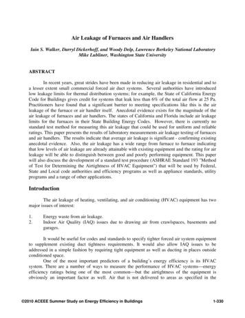
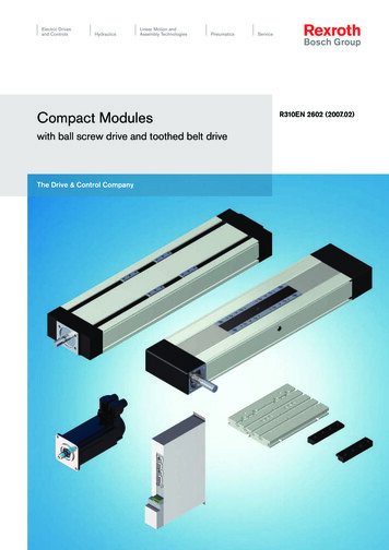
INSTALLATIONInstall the conditioned air plenum, ducts and air filters (notprovided) in accordance with NFPA 90B Standard for theInstallation of Warm Air Heating and Air-Conditioning Systems(latest edition).FIGURE 1It is the installers responsibility to make sure the strength ofthe ceiling and beams are adequate to support the weight ofthe air handler. See the below table for individual weights permodel.ModelWeight (lb.)CP18, 2360CE18, 2363CP19, 24, 2965CE19, 24, 2968CP25, 3070CE25, 3073FIGURE 2The soffit mount air handler is intended to be mounted in ahorizontal position above a dropped ceiling of adequatestrength. Figure 3 illustrates the cased air handler. Foruncased installation refer to figures 1 & 2. Properly attach unitwith lag bolts and washers through the provided top plateslots.Prior to installation, the installer must also consider air duct/drain connections, power supply wiring, and proper access forservicing and inspection.For free return (non-ducted return air) installation: To ensurethat return air is being pulled from the conditioned space only,the furred down area must be completely sealed (withexception of return air grille).FIGURE 33rev 1
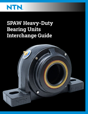
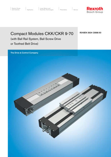
INSTALL CONDENSATE DRAINDetermine the drain connections to be used and note thedifference between the primary and secondary openings.Remove plugs from selected drain openings. It isrecommended that ¾″ male pipe thread PVC fittings be used atthe condensate pan. Hand tighten.the coil, air handling system or filter and will not be exposed tofreezing temperatures.If line makes a second trap, or has an extended run beforetermination, a vent tee should be installed after the trap closestto the pan. Connect the primary drain and route to an openTubing for all condensate drains should be a minimum of 7/8″ drain, sump, or sewer line.OD. The drain should be pitched downward 1″ per 10′. Install a CAUTIONtrap as close to the coil as possible (2” minimum). Refer to If the coil is located in or above a living space where damagefigure 3.may result from condensate overflow, a separate ¾″ drain mustRoute drain line so that it does not interfere with accessibility to be provided from the secondary drain connection (or a FloatSwitch can be used - refer to kit instructions for installationFIGURE 3procedures). Run this drain to a place in compliance with localDrain Trap and Vent Teeinstallation codes where it will be noticed when unit isoperational. Condensate flowing from the secondary drainindicates a plugged primary drain.Vent must extend a minimum ofDrain Pan2” above the drain pan2” Min.Prime the trap with water. Test line for leaks. Verify water flowwith unit in operation.It is recommended to install a support to the drain lineimmediately after the tee.Vent“T”Clean OutPress in(DO NOT GLUE)Drain Line3/4” MPT ConnectorReducing Tee with1” Slip Hex Plug2” Min.Pitch horizontaldrain linesdownward 1” per 10'Insulate pipe as neededREFRIGERANT PIPING & FLOW CONTROLSRefrigerant connections are 3/8″ ODF Liquid and 3/4″ ODFSuction. Refer to outdoor unit manufacturer’s recommendationon line sizing.3. Insert the desired piston into the distributor assembly.During brazing of refrigerant lines place a wet rag aroundsuction line to protect cabinet or ceiling from overheating.Maintain a minimum of 1.5″ from refrigerant brazingconnections and cabinet or ceiling.5. Re-install hex nut to body and torque to 10 ft-lbs.4. Inspect “O” ring and replace if damaged. Ensure gasket isin place.THERMAL EXPANSION VALVESAs shipped from the factory, the TXV installed in each coil ischosen for the nominal BTUH capacity of the coil. Attach andinsulate the TXV bulb outside of the cabinet to the main suctionline no more than one foot from the suction line connection.Refer to nomenclature to determine type of flow controlinstalled and needed for your application. Evaporator coils areshipped from the factory with florator pistons or TXVassemblies. Florator pistons and TXV kits are available for fieldconversion.Field installed TXV kits are also available. Refer to engineeringguide or price sheet for sizes, and kit instructions for installationprocedures.PISTONSAs shipped from the factory, the piston installed in each coil ischosen for the nominal BTUH capacity of the coil. Verify withthe condenser recommendation that proper florator piston isselected.REFRIGERANT LINE INSTALLATIONADP recommends installing a filter drier and sight glass in theliquid line. While brazing, purge the system with Nitrogen toprevent contamination. ADP recommends reattaching andinsulating the TXV sensing bulb at a 10 to 2 o’clock position onthe suction line, outside the coil housing, no more than one footfrom the connection. Evacuate the system to 500 microns toensure proper air and moisture removal (Note: Deepevacuation or triple evacuation method recommended). Openthe suction service valve slowly and allow the refrigerant tobleed into the system before opening the liquid service valve.When changing pistons use the following procedure:1. Loosen hex nut located on liquid line and separate fromdistributor assembly.2. Remove the existing piston from inside the distributorassembly4rev 1
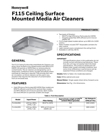
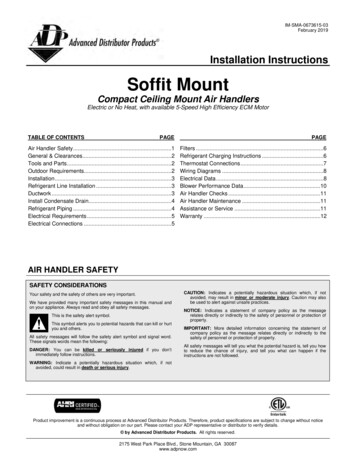
FIGURE 4Side View of Piston OrificeLiquid LineTeflon O-Ring SealHex NutADP PistonDistributor AssemblyCoil CabinetELECTRICAL REQUIREMENTS All field wiring must be done in accordance with NationalWARNINGElectrical Code, applicable requirements of UL and localcodes, where applicable. Electrical wiring, disconnect means and over-currentprotection are to be supplied by the installer. Refer to theair handler rating plate for maximum over-currentprotection, minimum circuit Ampacity, as well asoperating voltage.Electrical Shock HazardElectrically ground electric heater.Connect ground wire to ground terminal marked “GND”. The power supply must be sized and protected accordingUse copper wire rated for supply connection.to the specifications supplied on the product.Correct wire gauge is shown in the chart below. This air handler is factory configured for 240 Volt, singleFailure to follow these instructions can result in death orelectrical shock.Rating Plate AmpacityAWG21-301031-40841-606phase, 60 cycles. For 208 Volt applications, see “208 VoltConversion” in the “Make Electrical Connections” section. For optional electric heater applications refer to theinstructions provided with the accessory for proper installation.NOTE: Use copper conductors only.ELECTRICAL CONNECTIONS1. Models with electric heat: Determine the number ofcircuits needed to supply the heater with electrical power.See the air handler Accessory Kit label for number ofcircuits and ratings.2. Disconnect all power supplies.3. Remove the control panel.4. Using the pre-punched wiring holes, install UL listed wiresand fittings.5. Connect appropriate size wire to the pull disconnectterminals.6. Connect green ground wire(s) (1 or 2) to the groundterminal(s) (1 or 2) marked “GND”.7. Install conduit-opening plugs in any unused openings.8. Reinstall the air handler control panel.9. Reconnect power.10. Dispose of all remaining parts.WARNINGElectrical Shock HazardDisconnect all power supplies before servicing.Replace all parts and panels before operating.Failure to do so can result in death or electrical shock.5rev 1
FILTERSFilters are not provided with unit, and must be supplied andinstalled in the return air system by the installer. A fieldinstalled filter grille is recommended for easy and convenientaccess to the filters for periodic inspection and cleaning. Filtersmust have adequate face area for the rated air quantity of theunit.REFRIGERANT CHARGING INSTRUCTIONSWhen charging in cooling mode, the outdoor temperatureshould be 60 F or higher. To allow the pressures to stabilize,operate the system a minimum of 15 minutes betweenadjustments. When adjusting charge to systems with microchannel outdoor coils, make small (1 ounce or less)adjustments as these systems are very sensitive to refrigerantcharge.If the system is undercharged after the initial charge, addrefrigerant until the sight glass is clear and recommendedpressures, temperatures, sub-cooling and superheat can beobtained. If the system is overcharged after the initial ,temperatures, sub-cooling and superheat can be obtained.TXV Charging2, 3, 4 – Use the charging method recommendedby the outdoor unit instructions. Alternatively, ADPrecommends charging to 12 F sub-cooling for AC units and10 F sub-cooling for heat pump units. In addition, if equippedwith an adjustable valve, adjust to 10 F superheat.1. If any problems or questions regarding charge occur,contact customer service.Notes:2. OEM charging methods vary depending on design andapplication. Verify all recommended pressures, temperatures,sub-cooling and superheat settings result in the proper charge.Fixed Orifice Charging2, 3, 4 – Use the superheat recommended by the outdoor unit instructions. Alternatively, ADPrecommends charging to the superheat table below.3. ADP coils may require charge compensation due to sizevariation versus the OEM coil.4. Temperatures are 2 F unless otherwise recommended.For heat pump units initially charged in the cooling mode, finaladjustments to charge in the heating mode are acceptable ifnecessary. Some heat pump units require charging in theheating mode. In this case, refer to the outdoor instructions forrecommended charging procedures.6rev 1
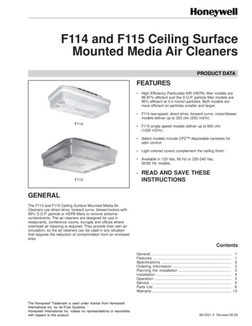
LOW VOLTAGE THERMOSTAT CONNECTIONSThermostat Connections: 2-speed MotorNOTE: When the room thermostat calls for second stageheat, the first stage (heat pump) operation must belocked out.Low Voltage Thermostat Connections – 5-speed ECM Constant Torque MotorFor 2 stage outdoor units: Use the airflow chart to identify the desired CFM for 1st and 2nd stage operation. For 1st stage, connect Y1 from the thermostat to the desired Tap on the terminal board. For 2nd stage, connect Y2 from the thermostat to the desired Tap on the terminal board.Cooling Application with Electric HeatHeat Pump Application with Electric Heat7rev 1
WIRING DIAGRAM2-speed MotorELECTRICAL DATA2-speed MotorUnit Size(All have electric heat)18, 1923, 24, 25, 2930[1][2]Heating CapacitykWBTUHBlower AmpsMinimum Circuit Ampacity240 V [1]240 V [1]208 V240 V208 V240 V3.05.06.08.03.05.06.08.010.0 .4Pull DisconnectAmps Per Stage30304545303045456030454560For 208 Volts use .751 correction factor for kW & MBTUH.10kW not available in -23 model8rev 1
WIRING DIAGRAMECM Constant Torque MotorELECTRICAL DATAECM Constant Torque MotorUnit Size(All have electric heat)18, 1923, 24, 25, 2930Heating CapacitykWBTUH240 V3.05.06.08.03.05.06.08.010.05.06.08.010.0[1]240 9634,12017,06020,47227,29634,120Blower AmpsMinimum Circuit Ampacity208 V240 V208 V240 127.533.844.254.527.533.844.254.5Pull DisconnectAmps Per Stage30304545303045456030454560[1] For 208 Volts use .751 correction factor for kW & MBTUH.9rev 1
BLOWER PERFORMANCE DATA2-speed PSC Motor: All data is given while air handler is operating with a dry coiland without air filter installed. Speeds marked *bold with asterisk are the factory speedsettings for both heating and cooling. Heating speeds should not be reduced below factory setting.ECM Constant Torque Motor: All data is given while air handler is operating with a dry coiland without air filter installed. For cooling select the tap that corresponds with the desiredCFM Heating speeds should not be reduced below factory setting.10rev 1
AIR HANDLER CHECKSCheck Blower OperationWARNING1. Set thermostat to FAN ON.2. The indoor blower should come on.Electrical Shock HazardCheck Electric Heater (if used)Disconnect all power supplies before servicing.Replace all parts and panels before operating.1. Set thermostat to call for auxiliary heat (approximately5 F above ambient temperature). The indoor blower andauxiliary heat should come on together. Allow a minimumof three minutes for all sequencers to cycle on.Failure to do so can result in death or electrical shock.2. Set the thermostat so it does not call for heat. Allow up tofive minutes for all sequencers to cycle off.Check AirflowCooling Blower Speed: For proper cooling operation, the airflow through theindoor coil should be between 350 and 450 CFM per tonof cooling capacity (350 - 450 CFM per 12,000 BTU/HR)based on the rating of the outdoor unit. The cooling blower speed is factory configured to providecorrect airflow for an outdoor unit that matches themaximum cooling capacity rating of the air handler. If the outdoor unit is smaller than the maximum coolingcapacity rating for the air handler, the cooling blowerspeed may need to be changed. Refer to “BlowerPerformance Data.”IMPORTANT: The cooling blower speed must be set to providea minimum of 350 CFM airflow per ton (12,000 BTU/HR) ofoutdoor cooling capacity.AIR HANDLER MAINTENANCEAt the beginning of each heating season the unit should beserviced by a qualified installer or servicing agency.ASSITANCE OR SERVICEIf you need further assistance, you may contact us at theaddress below with any questions or concerns. Please includea daytime phone number in your correspondence.Advanced Distributor Products1995 Air Industrial Park RoadGrenada, MS 38901www.adpnow.com11rev 1
ADP AIR HANDLER LIMITED WARRANTYTerm of WarrantyEquipment InformationAdvanced Distributor Products (ADP) warrants that productssold shall be of merchantable quality, free of defects in materialand workmanship, under normal use and service, for a periodof five (5) years from the date of installation, not to exceed six(6) years from the date of manufacture subject to the terms ofADP’s limited warranty.Please complete information below and retain this warranty forrecords and future reference.For information on this product’s warranty, including accessingcomplete warranty terms, registering for an extended warranty*or instructions on filing a warranty claim, please go towww.ADPwarranty.com.Serial Number:* In such states or provinces where registration requirementsare prohibited, failure to complete registration by theconsumer does not diminish his or her warranty rights.Installation Date:Unit Model Number:Installing Contractor:Phone:
Install the conditioned air plenum, ducts and air filters (not provided) in accordance with NFPA 90B Standard for the Installation of Warm Air Heating and Air-Conditioning Systems (latest edition). It is the installers responsibility to make sure the strength of the ceiling and beams are adequate to support the weight of the air handler.