Transcription
Installation ManualVision Indoor Air HandlersModels CAC/CAH 003—090 G 2013 Daikin McQuayIM 672-9Group: Applied Air SystemsPart Number: IM 672Date: May 2013
Table of ContentsIntroduction . . . . . . . . . . . . . . . . . . . . . . . . . . . . . . . . . 3Operation . . . . . . . . . . . . . . . . . . . . . . . . . . . . . . . . . . 26General Information . . . . . . . . . . . . . . . . . . . . . . . . . 3Startup Checks . . . . . . . . . . . . . . . . . . . . . . . . . . . . 26Receiving and Handling . . . . . . . . . . . . . . . . . . . . . . 3VFD Setup . . . . . . . . . . . . . . . . . . . . . . . . . . . . . . . . 27Unit Storage . . . . . . . . . . . . . . . . . . . . . . . . . . . . . . . 4Fan Startup . . . . . . . . . . . . . . . . . . . . . . . . . . . . . . . 27Mechanical Installation . . . . . . . . . . . . . . . . . . . . . . . 5Fan Wheel Alignment . . . . . . . . . . . . . . . . . . . . . . . 28Service Clearances . . . . . . . . . . . . . . . . . . . . . . . . . . 5Optional Piezometer RingAirflow Measurement Device . . . . . . . . . . . . . . . . . . 31Rigging . . . . . . . . . . . . . . . . . . . . . . . . . . . . . . . . . . . 5Unit Leveling . . . . . . . . . . . . . . . . . . . . . . . . . . . . . . . 7Assembling Sections . . . . . . . . . . . . . . . . . . . . . . . . . 8Panels, Frame Channels, and Doors . . . . . . . . . . . 12Injected-Foam Insulated Panels . . . . . . . . . . . . . . . 13Operating Limits . . . . . . . . . . . . . . . . . . . . . . . . . . . 32Fan Vibration Levels . . . . . . . . . . . . . . . . . . . . . . . . 32Maintenance . . . . . . . . . . . . . . . . . . . . . . . . . . . . . . . 33Periodic Maintenance . . . . . . . . . . . . . . . . . . . . . . . 33Field Mounting Junction Boxes andOther Components . . . . . . . . . . . . . . . . . . . . . . . . . 14Ball Bearing Lubrication . . . . . . . . . . . . . . . . . . . . . 33Face and Bypass Section Mounting . . . . . . . . . . . . 14Filters . . . . . . . . . . . . . . . . . . . . . . . . . . . . . . . . . . . . 39Multizone Assembly . . . . . . . . . . . . . . . . . . . . . . . . 16Coils . . . . . . . . . . . . . . . . . . . . . . . . . . . . . . . . . . . . 40Duct Connections . . . . . . . . . . . . . . . . . . . . . . . . . . 18Removing and Replacing Components . . . . . . . . . . 40Mounting Actuators . . . . . . . . . . . . . . . . . . . . . . . . . 18Parts . . . . . . . . . . . . . . . . . . . . . . . . . . . . . . . . . . . . . . 43Piping and Coils . . . . . . . . . . . . . . . . . . . . . . . . . . . 19Replacement Parts . . . . . . . . . . . . . . . . . . . . . . . . . 43Water Heating Coils . . . . . . . . . . . . . . . . . . . . . . . . 22Service and Warranty Procedure . . . . . . . . . . . . . . 44Drain Pan Traps . . . . . . . . . . . . . . . . . . . . . . . . . . . 22Warranty . . . . . . . . . . . . . . . . . . . . . . . . . . . . . . . . . 44Internal Isolation Assembly Adjustment . . . . . . . . . . 22Warranty Return Material Procedure . . . . . . . . . . . . 44Electrical Installation . . . . . . . . . . . . . . . . . . . . . . . . 25Check, Test, and Start Procedure Form . . . . . . . . . 45Wiring . . . . . . . . . . . . . . . . . . . . . . . . . . . . . . . . . . . 25Quality Assurance Survey Report . . . . . . . . . . . . . 47Fan Drive Adjustments . . . . . . . . . . . . . . . . . . . . . . 34Control Wiring . . . . . . . . . . . . . . . . . . . . . . . . . . . . . 252IM 672-9
IntroductionIntroductionGeneral InformationReceiving and HandlingVision indoor air handlers are not designed to be weatherresistant. Do not install them outdoors.The system design and installation must follow acceptedindustry practice as described in the ASHRAE Handbook, theNational Electric Code, and other applicable standards. Thisequipment must be installed in accordance with regulations ofauthorities having jurisdiction and all applicable codes.Installation and maintenance must be performed by qualifiedpersonnel familiar with applicable codes and regulations andexperienced with this type of equipment. Sheet metal parts,self-tapping screws, clips, and such items inherently havesharp edges; the installer should exercise caution.CAUTIONSharp edges and coil surfaces are a potential injuryhazard. Avoid contact with them.ATTENTIONLes bords tranchants et les surfaces des bobines sontun risque de blessure. Ne les touchez pas.1. Carefully check items against the bills of lading toverify all crates and cartons have been received.Carefully inspect all units for shipping damage. Reportdamage immediately to the carrier and file a claim.2. Vision air handler units are constructed of galvanizedor painted steel and are inspected thoroughly beforeleaving the factory. Take care during installation toprevent damage to units.3. Take special care when handling the blower section.All fans are dynamically balanced before leaving thefactory. Rough handling can cause misalignment ora damaged bearings or shaft. Carefully inspect fansand shaft before unit installation to verify this has nothappened.4. Handle the zone damper of the multi-zone units withspecial care. Zone dampers are set and inspected beforeleaving the factory, but should be checked on arrivalto the job to verify the bell arm and connecting rod setscrews did not become loose in shipment.NomenclatureCAH 003 G D A CModelCAH Custom modular air handlerCAC Custom modular componentUnit cross sectionC Standard unit cross sectionM Custom size cross sectionNominal unit size(cataloged size—nominal square foot of coil)003, 004, 006, 008, 010, 012, 014, 017, 021,025, 030, 035, 040, 050, 065, 080, 085, 090Motor locationA Motor along side of fan housingD Motor down stream of belt-drive plenum fanF Motor on inline fanG Motor downstream of direct-drive plenum fanH Motor downstream of fan arrayT Motor behind twin fan housingVintageUnit type/coil positionB Blow-through cooling coil locationD Draw-through cooling coil locationH Heating onlyV Vent onlyM MultizoneIM 672-93
IntroductionIntroductionUnit Storage Store on a level surface in a clean, dry location wheretemperature can be controlled if possible. Pack fan and motor bearings (unless motor bearings aresealed) with compatible grease with the shaft stationary.After grease has been installed, rotate shaft about 10rotations. Isolate unit from shock and vibration. Once a month, rotate shaft a minimum of 10 revolutions.Insure the stopped position is different than the originalposition. Coat shafts with lubricant as needed to preventcorrosion. A descant bag may be hung in the interior of the unit tominimize corrosion in humid storage environments. Donot clean galvanized steel surfaces with oil dissolvingchemicals. This may remove the protective coating andaccelerate corrosion. Do not allow coverings to trap moisture on galvanizedsurfaces.4Belt-Driven fans Reduce belt tension by at least 50% or remove the belts.Remove belts if they will be subjected to temperaturesexceeding 85 F to avoid deterioration. Remove belt guard when adjusting belts Reduce belt tension prior to removing or installing belts. Removing or installing tensioned belts may causepersonal injury and damage to the sheaves, belts,bearings or shafts. Adjustable sheaves should be opened as wide as possibleand the adjustment threads lubricated so they do notcorrode. Be careful not to put lubricant on the beltrunning surfacePrior to start up Set screws on bearings, fan wheels, and sheaves need tobe checked for proper torque. Also check bolt torque forany taper lock hubs either on the wheel or sheaves. Check sheaves for corrosion. Significant corrosion cancause belt or sheave failure. Purge old grease from fan bearings while rotating theshaft to distribute the new grease evenly and preventbearing seal failure. Correctly align and tension belts. See General Rules ofTensioning on page 38.IM 672-9
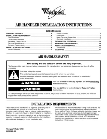
Mechanical InstallationMechanical InstallationFigure 2: Service Clearance for Electrical Power DevicesService ClearancesIn addition to providing adequate space around the unit forpiping coils and drains, access to at least one side of the unitis always required to allow for regular service and routinemaintenance, which includes filter replacement, drain paninspection and cleaning, fan bearing lubrication, and beltadjustment. Provide sufficient space—at least equal to thelength of the coil—on the side of the unit for shaft removaland coil removal. Space, at least equal to the length of the sidecoil, is required for coil removal. Space, at least equal to thefin height, is required for top coil removal. See Figure 1 forservicing space requirements.For routine maintenance purposes, access normally is obtainedthrough the access doors or by removing panels. Fan and filtersections are always provided with a service door on one side ofthe unit. If requested, doors can be provided on both sides ofthe unit. Optional service doors are available for most sectiontypes and are provided based on customer request. RiggingIf component replacement is required, the top panel alsocan be removed. If necessary, the unit can be disassembled.Maintain at least 54" of clearance in front of electrical powerdevices (starters, VFDs, disconnect switches and combinationdevices). Electrical power devices that are mounted on theside of the unit typically are up to 12" deep (Figure 2). Fansections with multiple fans have motor control boxes up to 16"deep when supplied with VFDs.Vision air handlers ship as separate sections, completelyassembled, or in modules of assembled sections. The unitmust be rigged as it ships from the factory. Do not rig unitsafter assembly. When a unit is provided with a factoryinstalled base rail, it can be lifted using the 2" diameter liftingholes located in the corners of each shipping section (Figure3). If a unit does not have a base rail, rig it using straps or asling. Fasten the strapping under the skid that ships with thesection (Figure 4).Figure 1: Servicing Space RequirementsTo prevent damage to the unit cabinetry, use spreader bars.Position spreader bars to prevent cables from rubbing the frameor panels. Before hoisting into position, test lift for stability andbalance. Avoid twisting or uneven lifting of the unit. Figure 3: Units on Base Rails IM 672-9 5
Mechanical InstallationMechanical InstallationFigure 4: Units on SkidsClass II plenum fans that are stacked on another section maybe lifted using the methods shown in the following figures.The shipping brackets must remain in place and be tight inorder to lift using this method. Figure 6 shows a belt-drivefan with field supplied eye bolts that are screwed into factoryinstalled hex AVK fasteners in the main channels supportingthe fan. Figure 7 shows a direct-drive fan with field suppliedeye bolts on the motor end and straps around the springbracket on the inlet end. When factory installed hex AVKfasteners are installed, they should be used for lifting. Whenthey are not installed, it is acceptable to lift from the shippingbrackets on the fan. Figure 8 shows dual fans being lifted in asimilar manner as the single direct-drive fan. An eight pointlift must be used for dual fans to make sure both fans aresupported properly and the cabinet structure does not becomeoverloaded along the center.If the fan section is connected to another section such as aplenum or access section, then DO NOT attempt to lift bothsections using just the fan section. The other section(s) mustbe supported separately using straps.Fan sections greater than 108" wide that are stacked onanother section that are not Class II plenum fans areconstructed with internal fan support frames that haveintegral lifting brackets (Figure 5). After the fan section isplaced in position, remove and discard the lifting brackets.Install the small panels provided to complete the unit cabinetareas where the lifting brackets were located.Figure 6: Belt-Drive Class II Plenum Fan Stacked UnitFigure 5: Large Fan Sections Stacked on Top of a LowerSection 6IM 672-9
Mechanical InstallationFigure 7: Direct-Drive Class II Plenum Fan Stacked UnitUnit LevelingPlace the equipment on a flat and level surface. Where thesurface irregularities could cause the equipment to distort,use a shim so the base of the unit is a straight line. Unevenor distorted sections cause misfit or binding of the doors andpanels and improper draining of drain pans. Units that areover 108" wide must rest on a flat surface for the entire widthof the base rails or must be shimmed at one or more pointsalong the length of the rails to prevent distortion or sagging ofthe support rails (Figure 9).Figure 9: Leveling the UnitFigure 8: Direct-Drive Class II Dual Plenum Fan StackedUnit IM 672-9 7
Mechanical InstallationAssembling SectionsExternal Section-to-Section MountingVision air handling units can ship fully assembled or asseparate shipping sections. Rig units that require fieldassembly of shipping sections into position first. Shippingsections are provided with a connection splice joint attachedon the leaving air side of the shipping section. The splicejoint is insulated and provides an air-tight seal between twosections once they are assembled together. If the splice jointwas bent during shipping or rigging, restore it to its originalposition. (Figure 19 on page 11).Figure 10: Horizontal Joining Sections Horizontal Airflow Section Mounting1. Rig the unit into position and lineup shipping sectionsin the direction of air flow. Pull sections together tofasten. Use a furniture clamp or straps and a ratchet tohelp pull the sections together securely (Figure 10).2. If the unit has a factory-installed base rail, first fastenbase rails together using the 3/8"-16 5" bolts located inthe splice kit provided with the unit.a. To fasten two shipping sections together, fourbolts are needed (two on each side of the unit).The bolts are run from one base rail into theother and fastened with a nut. Complete eachsection bottom and top before attaching additionalsections.Figure 11: Frame Channel Stiffener Plates (Custom AirHandler Units Only)3. If no base rail is provided, fasten the unit in the samemanner on the bottom and top frame channels.4. Once the sections are positioned together, remove thefastener in each of the channel corners (on the matingedges in the channel piece).5. Place a flat section joining plate (found in the splice kit)over the two coned holes in the channels, so that theplate spans the two sections.6. Replace the fasteners in their original position, throughthe joining plate.7. For certain Custom Air Handler units, use the providedsection joining plates to fasten sections together. Spacethem as shown in Figure 11. Using the provided ¼"-14 x1" self tapping screws, drill screw the joining plates intothe frame channel on each section, keeping unit sectionstight together. Follow instruction drawing included inthe assembly kit.8IM 672-9
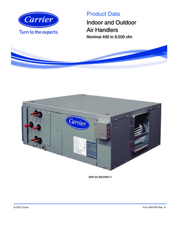
Mechanical InstallationVertical Inverted Airflow Section MountingExtended Coil Section MountingFor vertical or inverted arrangements, before lifting anytop mounting sections into place, rig into place and fastentogether the bottom tier of sections. Once bottom levelsections are in place and secured, lift stacked components andfasten using the following procedure:The extended coil section is 6" wider than all other sections ofthe same unit size. The extension is always located on the coilconnection side of the unit. Because the extended coil sectionis wider than other sections, it always ships as a separateshipping section, and must be joined to other sections in thefield. To join an extended coil section to other components,first follow the Horizontal Airflow Section Mounting‚ page7 steps to secure the opposite connection side. To fasten theconnection side, use the following procedure:NOTE: See Face and Bypass Section Mounting on page14 for the exception to this procedure.1. The vertical/inverted section has a splice jointextending out the top of the bottom joining section.Lower the section that is to be positioned over theopening over the splice joint to seal the connectionbetween the two sections.2. The two sections are fastened together at the fourbottom corners of the mating edge. To fasten thecorners located on the end of the unit (where bottomsection and top section walls are flush with each other),remove the flat head fasteners in the corners of bothsections.3. Cover the coned holes with a flat joining plate andreplace the flat head fasteners in the holes to secure thejoining plate to both sections (Figure 12).4. When one section is deeper than the other, secure thetwo sections using an L-shaped joining plate. To securethe L-shaped bracket, remove the flat head fastenerfrom the corner, position the bracket over the hole,and replace the flathead fastener with a 5/16"-18 1"bolt. Once the bolt is in place, secure the bracket to theadjoining section with a 1/4" 1" drill screw. Repeat thesame procedure on both corners of the unit (Figure 12).Figure 12: Vertical/Inverted Joining Sections 1. If the unit has a factory-installed base rail, the extendedcoil section base rail is also 6" wider than the adjoiningbase rail. Extended coil section base rails on theconnection side are fastened together using the 3/8"-16by 3" bolts located in splice kit provided with the unit(Figure 13).2. If no base rail is provided, the section is fastened in thesame manner on the bottom and top. Once the sectionsare positioned together, remove the fastener in thecorner of the channel piece of the section mating to theextended coil section (Figure 13).3. Place an L-shaped section joining plate (located in thesplice kit) over the coned hole in the channel.4. Replace the flat head fastener originally used in thecorner with a 5/16"-18 1" bolt and fasten it through theL-shaped joining plate.5. Position the L-shaped joining plate so it butts up againstthe extended coil section frame channel. To secure theplate to the extended coil section, run two 1/4" 1"drill screws through the joining plate and into the framechannel.Figure 13: Extended Coil Section JoiningT o pV ie w A(2 ) 1 /4 x 1D r ill S c r e w sB o tto mw ith b a s e r a ilA IM 672-99
Mechanical InstallationSide-by-Side Heatwheel Section JoiningFigure 15: Base Plate DetailThe side-by-side heatwheel will have two individual sectionsparallel in the direction of airflow to be attached to either side.Each section will attach to the heatwheel section and then tothe other parallel section.1. Rig the unit into position and line shipping sections upin direction of air flow. Sections must be pulled togetherto fasten using a furniture clamp or straps.a. If the heatwheel section width is greater than143", then rig the section into position using thetwo removable lifting channels. After section isproperly placed, remove cotter pin and bolts fromlifting channel and discard as seen in Figure 14Figure 14: Cotter Pin and Bolt Detail7. Replace the fasteners in their original position, throughthe joining plate.8. Assemble the next section parallel to the assembledsection by following Steps 1 – 7 above.9. Using the 3/8"-16 1" bolts provided, fasten the twoparallel sections’ bases together as seen in Figure 16.10. Using appropriate safety equipment if necessary,remove the fastener in each of the channel corners onthe top between the two parallel sections and discard.2. If included, remove center base plates that are attachedto the base channels and save for Step 4.11. Use the 2 2 holed splice plate with 2 5/16"-18 1"screws and 2 ¼" drill screws. The 2 5/16"-18 1"screws will go into the frame channel holes and the2 ¼" drill screws will go into the heatwheel framechannel as show in Figure 17.Figure 16: Base Section Detail3. If the unit has a factory installed base rail, fasten thebase rails together using the 3/8"-16 5" bolts located inthe splice kit provided with the unit.a. To fasten two shipping sections together, twobolts are required on the one side. The bolts arerun from one base rail into the other and fastenedwith a nut. Complete each section bottom and topbefore attaching additional sections.4. Assemble the center base plates as show in Figure 15,leaving a 5/16" space between each plate to slide ontosection base channels to center point of section width.5. Once the sections are positioned together, remove thefastener in each of the channel corners (on the matingedges in the channel piece).6. Place a flat section joining plate (found in the splice kit)over the two coned holes in the channels, so the platespans the two sections.10IM 672-9
Mechanical InstallationFigure 17: Frame Channel DetailFigure 19: Internal FasteningInternal Section-to-Section MountingIf desired, shipping sections can be fastened togetherinternally. To fasten internally, run field-provided #10 sheetmetal screws or drill screws (4" long maximum) through theinterior frame channel of one unit into the splice joint of theneighboring section.The section-to-section splice joint is always provided on theleaving air side of a shipping section and seals against theframe channel on the entering-air side of the adjoining section.Align the splice joint to seat into the mating gasket to providean air seal. If the splice joint was bent during shipping orrigging, restore it to its original position (Figure 19).For Custom Air Handler units, ensure that the D-gasket isattached to the entering air side frame channel (Figure 18). Ifit has dislodged during shipping, restore to original location.Ceiling HungWhen a unit is ceiling hung, support it with a base rail, angleiron, or channel. The Vision air handler is not designed to besuspended from the top of the unit. Before hanging, rig andcompletely assemble the unit. See Assembling Sections onpage 8.Ceiling Hung Using Base RailThe optional base rail provided by the factory has 5/8" diameterholes in each corner to run hanger rods through. To properlysupport the unit and maintain unit integrity, support eachshipping section with hanger rods in each corner (Figure 20).Figure 20: Ceiling Suspended with Base RailFigure 18: D-Gasket Placement Detail (Custom Air HandlerUnits only)Ceiling Hung Using Angle Iron ChannelInstall field-provided angle iron or channels per SMACNAguidelines. When a unit is unitized (ships in one piece), channelsupport each component under the unit width (Figure 21).NOTE: The supporting angle iron must fully support the 2"frame channel at each section joint.IM 672-911
Mechanical InstallationWhen a unit is sectionalized (ships in multiple sections),channel support each component under the unit width andprovide support under the full length of the unit base (Figure22). Locate hanger rods so they do not interfere with accessinto the unit.Ceiling suspension using the unit base rails is limitedto unit cabinet widths less than 108". Support units withcabinets 108" wide and greater with structural membersdesigned to support the unit at the ends and at intermediatepoints along the base rails.Figure 21: Ceiling Suspended w/o Base Rail—Unitized ConstructionPanels, Frame Channels, and DoorsPanel RemovalTo remove a side or top panel, remove the flat head Torx 30fasteners along the sides of the panel. Lift off the panel afterremoving all fasteners.Frame Channel RemovalFrame channels that run the length of the unit along the topcan be removed to allow access to both the side and top ofthe unit. To remove the frame channel, first remove the sidepanel(s). Once the side panel is off, remove the flat head Torx30 fasteners in the corner of the frame channels. Then pullthe frame channel out the side. Remove any panel screws thatare within one inch of the of the frame since they are engagedinto the gasketed flange of the frame (Figure 23).Figure 23: Removing Panel Screws Figure 22: Ceiling Suspended w/o Base Rail—Modular Construction12IM 672-9
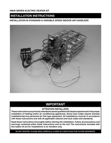
Mechanical InstallationFan Section DoorsNOTE: Opening fan section doors requires using a 1/2"socket wrench (Figure 24), which satisfies ANSIstandards and other codes that require the “use oftools” to access compartments containing movingparts or electrical wiring.CAUTIONSharp edges and coil surfaces are a potential injuryhazard. Avoid contact with them.ATTENTIONLes bords tranchants et les surfaces des bobines sontun risque de blessure. Ne les touchez pas.Figure 24: Opening Fan Section DoorInjected-Foam Insulated PanelsVision air handlers are furnished with double-wall, injectedfoam insulated panels. Foam panels are stronger, morerigid, and lighter than panels with fiberglass insulation.The insulation R-value is improved to 13. However, foaminsulation can burn when exposed to flame or other ignitionsources and release toxic fumes. Take care in cutting andsealing all field-cut openings in these panels.Panel Cutting Procedure1. Determine the number and location of holes requiredfor electrical conduit, piping, and control wiring asfollows (also refer to Figure 25):a. Check that adequate space is available inside theunit for conduit or pipe routing.b. Do not locate holes in a panel that provides accessto key maintenance components such as filtersand fan assemblies.c. Do not locate where the conduit or piping blocksairflow or obstructs hinged access doors.2. Once a proper location is determined, drill a small pilothole completely through the panel. Then use a sharphole saw or a saber saw and cut from each side of thepanel.3. Seal the double-wall panel on each side with anindustrial/ commercial grade silicone sealant or ductseal compound. It is extremely important to seal eachpanel hole or penetration securely so that it is airtight,watertight, and that there is no exposed foam insulation.WARNINGFlame and smoke can causeequipment damage, severe personalinjury, or death.Before operating unit, seal all pipingand wiring holes on both inner and outerpanels with an industrial grade siliconesealant or duct seal compound. Do notuse a cutting torch or expose panelto fire. Panel damage can occur.ATTENTIONLa fumée et les flammes peuventendommager le matériel et causesrdes blessures graves ou la mort.Avant d’utiliser le dispositif, obturertous lestrous de passage de tubulureset de filsménagés dans les panneauxintérieurs etextérieurs au moyen d’unepâte à base desilicone ou d’un masticd’étanchéite âconduits de qualitéindustrielle. Ne pas se servir d’unchalumeau coupeur ni exposer lespannequx à une flamme nuepour nepas risquer de les endommager.IM 672-913
Mechanical InstallationFigure 25: Cutting/Sealing Injected-Foam Insulated panelsCut hole from both sides of panelSeal completely with siliconesealant or duct seal compoundFace and Bypass Section MountingInternal face and bypass, and external face and bypass forsizes 003 to 035 are mounted together using the instructionsfor horizontal components and do not require additionalinstruction.For all size units that bypass directly into a vertical fansection and for sizes 040 to 090 with external face andbypass, use the following instructions.Bypass Into a Vertical Fan SectionProp 65—Substances in fuel or from fuel combustion can cause personal injury or death,and are known to the State of California to cause cancer, birth defects or other reproductive harm.Field Mounting Junction Boxes andOther ComponentsFor field mounting 4" 4" or smaller junction boxes to thestandard panel exterior, use a minimum quantity of four, 3/16"diameter pop rivets. DO NOT use self-tapping drill screws.They will not tighten nor secure properly and panel damagecan occur.If larger, heavier components require mounting on unitpanels, use through-bolts with flat washers through both outerand inner panels. To maintain panel integrity, seal both endswith an industrial/commercial grade silicone sealant or ductseal compound.The unit frame channel is another excellent location forsecuring heavier components; self-tapping screws are notacceptable. Ensure that the location permits the full operationof all access doors and panels and does not interfere withother vital components.Vertical coil sections and the top mounted fan section alwaysship separately and must be mounted together at the jobsite. The vertical coil section and the bypass duct each has ajoining collar mounted on the leaving air side of the sectionand duct, respectively (Figure 26). The mounting collarfits into the side (bypass) and bottom (vertical coil section)openings in the fan section. To correctly position the collarsin the fan openings, assemble
2. Vision air handler units are constructed of galvanized or painted steel and are inspected thoroughly before leaving the factory. Take care during installation to prevent damage to units. 3. Take special care when handling the blower section. All fans are dynamically balanced before leaving the factory. Rough handling can cause misalignment or