Transcription
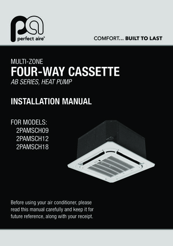
MULTI-ZONEFOUR-WAY CASSETTEAB SERIES, HEAT PUMPINSTALLATION MANUALFOR MODELS:2PAMSCH092PAMSCH122PAMSCH18Before using your air conditioner, pleaseread this manual carefully and keep it forfuture reference, along with your receipt.
If used as MULTI unit, please refer to the Installation & operation manuals packed with outdoor unit.
CONTENTSInstall according to this installation instructions strictly.If installation is defective, it will cause water leakage, electricalshock and fire.PagePRECAUTIONS.1INSTALLATION INFORMATION.2When installing the unit in a small room, take measuresagainst to keep refrigerant concentration from exceedingallowable safety limits in the event of refrigerant leakage.Contact the place of purchase for more information. Excessiverefrigerant in a closed ambient can lead to oxygen deficiency.ACCESSORIES.3INDOOR UNIT INSTALLATION.4OUTDOOR UNIT INSTALLATION.7INSTALL THE REFRIGERANT PIPE.9CONNECT THE DRAIN PIPE.12Use the attached accessories parts and specified parts forinstallation.Otherwise, it will cause the set to fall, water leakage, electricalshock and fire.ELECTRIC WIRING WORK.13INSTALLATION OF THE DECORATION PANEL.15TEST OPERATION.16Install at a strong and firm location which is able to withstandthe set' s weight.If the strength is not enough or installation is not properly done,the set will drop & cause injury.PRECAUTIONSThe appliance must be installed 2.5m / 8.2ft above floor.Keep this manual where the operator can easily find them.The appliance shall not be installed in the laundry room.Read this manual attentively before starting up the units.Before obtaining access to terminals, all supply circuits mustbe disconnected.For safety reason the operator must read the followingcautions carefully.The appliance must be positioned so that the plug is accessible.Installation must be performed in accordance with therequirement of NEC and CEC by authorized personnel only.The enclosure of the appliance shall be marked by word, or bysymbols, with the direction of the fluid flow.For electrical work, follow the local national wiring standard,regulation and this installation instructions. An independentcircuit and single outlet must be used.If electrical circuit capacity is not enough or defect in electricalwork, it will cause electrical shock or fire.The safty precautions listed here are divided into two categories.WARNINGUse the specified cable and connect tightly and clamp thecable so that no external force will be acted on the terminal.If connection or fixing is not perfect, it will cause heat-up or fireat the connection.If you do not follow these instrutions exactly, the unit maycause property damage, personal injury or loss of life.CAUTIONWiring routing must be properly arranged so that control boardcover is fixed properly.If control board cover is not fixed perfectly, it will cause heat-upat connection point of terminal, fire or electrical shock.If you do not follow these instrutions exactly, the unit maycause minor or moderate property damage, personal injury.If the supply cord is damaged, it must be replaced by anauthorized service technician or certified HVAC contractor inorder to avoid a hazard.After completing the installation, make sure that the unit operatesproperly during the start-up operation. Please instruct the customer onhow to operate the unit and keep it maintained.Also, inform customersthat they should store this installation manual along with the owner'smanual for future reference.An all-pole disconnection switch having a contact separation ofat least 0.12 in./3mm in all poles should be connected in fixedwiring.When carrying out piping connection, take care not to let airsubstances go into refrigeration cycle.Otherwise, it will cause lower capacity, abnormal high pressurein the refrigeration cycle, explosion and injury.WARNINGBe sure only trained and qualified service personnel to install,repair or service the equipment.Do not modify the length of the power supply cord or use ofextension cord, and do not share the single outlet with otherelectrical appliances.Otherwise, it will cause fire or electrical shock.Improper installation, repair, and maintenance may result inelectric shocks, short-circuit, leaks, fire or other damage to theequipment.1
If the refrigerant leaks during installation, ventilate the areaimmediately.Toxic gas may be produced if the refrigerant comes into theplace contacting with fire.There are inflammable materials or gas.There is acid or alkaline liquid evaporating.Other special conditions.The temperature of refrigerant circuit will be high, please keepthe interconnection cable away from the copper tube.The appliance shall be installed in accordance with nationalwiring regulations.After completing the installation work, check that the refrigerantdoes not leak.Toxic gas may be produced if the refrigerant leaks into theroom and comes into contact with a source of fire, such as afan heater, stove or cooker.Do not operate your air conditioner in a wet room such as abathroom or laundry room.An all-pole disconnection device which has at least 3mm / 0.1inclearances in all poles , and have a leakage current that mayexceed 10mA, the residual current device (RCD) having a ratedresidual operating current not exceeding 30mA, anddisconnection must be incorporated in the fixed wiring inaccordance with the wiring rules.CAUTIONGround the air conditioner.Do not connect the ground wire to gas or water pipes, lightningrod or a telephone ground wire.Inappropriate grounding mayresult in electric shocks.INSTALLATION INFORMATIONBe sure to install an earth leakage breaker.Failure to install an earth leakage breaker may result in electricshocks.To install properly, please read this "installation manual" atfirst.Connect the outdoor unit wires , then connect the indoor unitwires.You are not allowed to connect the air conditioner with thepower supply until the wiring and piping is done.The air conditioner must be installed by qualified persons.When installing the indoor unit or its tubing, please followthis manual as strictly as possible.While following the instructions in this installation manual, installdrain piping in order to ensure proper drainage and insulatepiping in order to prevent condensation.Improper drain piping may result in water leakage and propertydamage.If the air conditioner is installed on a metal part of thebuilding, it must be electrically insulated according to therelevant standards to electrical appliances.When all the installation work is finished, please turn onthe power only after a thorough check.Install the indoor and outdoor units, power supply wiring andconnecting wires should be at least 1 meter away fromtelevisions or radios in order to prevent image interference ornoise.Depending on the radio waves, a distance of 1 meter may notbe sufficient enough to eliminate the noise.Regret for no further announcement if there is any changeof this manual caused by product improvement.The appliance is not intended for use by young children orinfirm persons without supervision.INSTALLATION ORDERDon't install the air conditioner in the following circumstance:Indoor unit installation;There is petrolatum existing.Outdoor unit installation;There is salty air surrounding (near the coast).Install the refrigerant pipe;There is caustic gas (the sulfide, for example) existingin the air (near a hot spring).Connect the drain pipe ;The Volt vibrates violently (in the factories).Electric wiring work;In buses or cabinets.Installation of the decoration panel;In kitchen where it is full of oil gas.Test operation.There is strong electromagnetic wave existing.2
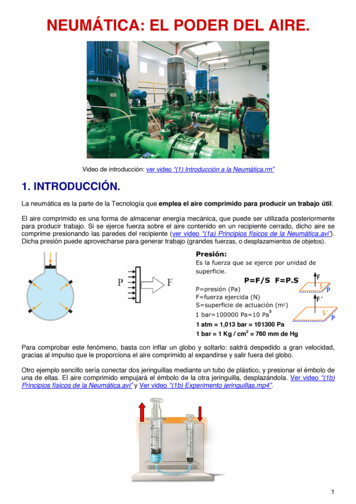
ACCESSORIESFor the following items, take special care duringconstruction and check after installation is finishedCheck if the following accessories are included with your unit.211X31X2XTickwhenchecked42XIs the indoor unit fixed firmly?The unit may drop,vibrate or make noise.Is the gas leak test finished?It may result in insufficient cooling or heating.71X651X1X 1XIs the unit fully insulated?Condensate water may drip.8Does drainage flow smoothly?Condensate water may drip.1XDoes the power supply voltage correspond to thatshown on the name plate?The unit may malfunction or components may burn out.9111X104X4XAre wiring and piping correct?The unit may malfunction or components may burn out.121XIs the unit safely grounded?Dangerous at electric leakage.Is the wiring size according to specifications?The unit may malfunction or components may burn out.11Is nothing blocking the air outlet or inlet of either theindoor or outdoor units?It may result in insufficient cooling or heating.12Are refrigerant piping length and additional refrigerantcharge noted down?The refrigerant charge in the system might not be clear.1 Remote control2 Batteries3 Remote control holder (on some models)4 Tapping screws (M310mm) (on some models)5 Installation and owner's manualNOTE6 Paper pattern for installation (on some models)All the pictures in this manual are for explanation purpose only.There may be slightly different from the air conditioner youpurchased ( depend on model ). The actual shape shall prevail.7 Metal champ (on some models)8 Drain hose (on some models)9 Expansible hooks (on some models)10 Installation hooks (on some models)11Throttle (on some models)12Anti-shock rubber (on some models)13Drain plug(only heat pump models)(with the outdoor unit)14Seal ring(only heat pump models)(with the outdoor unit)Optional accessoriesThis indoor unit requires installation of an optional decorationpanel.3
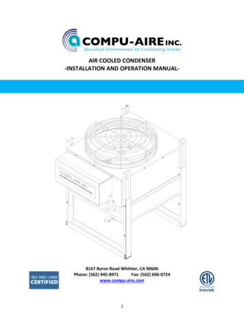
When the conditions in the ceiling are exceeding 300C / 860F and arelative humidity of 80%, or when fresh air is inducted into the ceiling,an additional insulation is required (minimum 10 mm / 0.4in thickness,polyethylene foam).2---1000/39.4inWhere optimum air distribution can be ensured.Where nothing blocks air passage.Where condensate water can be properly drained.Where the false ceiling is not noticeably on an incline.Where sufficient clearance for maintenance and service can beensured.Where there is no risk of flammable gas leaking.The equipment is not intended for use in a potentially explosiveatmosphere.Where piping between indoor and outdoor units is possiblewithin the allowable limit.(Refer to the installation manual of theoutdoor unit.)Keep indoor unit,outdoor unit,inter unit wiring and remotecontroller wiring at least 1 meter away from televisions andradios.This is to prevent image interference and noise in thoseelectrical appliances.(Noise may be generated depending onthe conditions under which the electric wave is generated,evenif 1 meter is kept.)When installing the wireless remote control kit,the distancebetween wireless remote control and indoor unit might be shorterif there are fluorescent lights who are electrically started in theroom. The indoor unit must be installed as far as possible awayfrom fluorescent lights.1000/39.4in-2)1000/39.4inSelect an installation site where the following conditions arefulfilled and that meets your customer's approval.1)290/11.4inSelecting installation site12Air inletAir outlet11000/39.4in21000/39.4in1.1260/10.2inINDOOR UNIT INSTALLATION2500/98.4in1.1000/39.4inUnit: mmDANGERDo not install the unit in an area where flammable materialsare present due to risk of explosion resulting in seriousinjury or death.Ceiling heightInstall this unit where the height of bottom panel is more than2.5m / 8.2ft so that the user cannot easily touch.3)Use installation hooks for installation.Check whether theceiling is strong enough to support the weight of the indoorunit.If there is a risk,reinforce the ceiling before installingthe unit.Space required for installation see the figure below (:air flowdirection)WARNINGIf the basis underneath the unit is not strong enough tosupport the weight of the unit, the unit could be fall out ofplace and cause serious injury.4
1.212Make the ceiling opening needed for installation whereapplicable.(For existing ceilings.)- Create the ceiling opening required for installation. From theside of the opening to the casing outlet, implement therefrigerant and drain piping and wiring for remote control(unnecessary for wireless type). Refer to each piping or wiringsection.- After making an opening in the ceiling, it may be necessary toreinforce ceiling beams to keep the ceiling level and to prevent itfrom vibrating. Consult the builder for details.3 647/25.5in523/20.6in570/22.4in2Relation of ceiling opening to unit and suspension boltposition.5411)2)Preparations before installation3)Install the installation hooks. (Use either a M8 or M10 sizebolt. )Use expansible hooks, sunken anchors or other field suppliedparts to reinforce the ceiling in order to bear the weight of theunit. Adjust clearance from the ceiling before proceeding further.Installation example see figure below.545/21.5in570/22.4in3 647/25.5in130 35mm1.2 6in20/0.8in1234Unit: mm12345678Installation hook pitch dimensionsIndoor unit dimensionsdecoration panel dimensionsRefrigerant pipingInstallation hook (Ў4)Ceiling opening dimensionsHanger bracketFalse ceilingNOTEAdjust the position to ensure the gaps between the indoorunit and the four sides of false ceiling are even. The indoorunit's lower part should sink into the false ceiling for24mm / 0.9in.124mm0.9in212Indoor unitFalse ceilingNOTE: Installation is possible with a ceiling dimension of 600 mm/ 23.6in(marked with * ) . However,to achieve aceiling-panel overlapping dimension of 15 mm / 0.6in, thespacing between the ceiling and the unit should be 20 mm/ 0.8in or less.If the spacing between ceiling and the unitis over 20 mm / 0.8in, attach sealing material in the partor recover the ceiling.5Ceiling slabExpansible hook (optional)Installation hook (optional)False ceilingFor other installation than standard installation,contact your dealer for details.
1.34) Check if the unit is horizontally levelled.Install the indoor unit- Do not install the unit tilted. The indoor unit is equipped with abuilt-in drain pump and float switch. (If the unit is tilted againstthe direction of the condensate flow (the drain piping side israised), the float switch may malfunction and cause water todrip.)- Check if the unit is levelled at all four corners with a water levelor a water-filled vinyl tube as shown in figure below.When installing optional accessories, read also the installationmanual of the optional accessories. Depending on the fieldconditions, it may be easier to install optional accessories beforethe indoor unit is installed (except for the decoration panel).However, for existing ceiling, install fresh air inlet component kitand branch duct before installing the unit.1)Install the indoor unit temporarily.- Attach the hanger bracket to the suspension bolt. Be sure tofix it securely by using a nut and washer from the upper andlower sides of the hanger bracket.- Securing the hanger bracket see figure below.121213122Water levelVinyl tube45) Remove the paper pattern for installation. (For new ceilingonly).12342)Nut (field supply)Washer (field supply)Hanger bracketDouble nuts (field supply,tighten)Fix the paper pattern for installation. (For new ceilings only)- The paper pattern for installation corresponds with themeasurements of the ceiling opening. Consult the builder fordetails.- The centre of the ceiling opening is indicated on the paperpattern for installation.- After removing the packaging material from the paper patten forinstallation, attach the paper pattern for installation to the unitwith the attached screws as shown in figure below.123123Paper pattern for installation(on some models)Center of the ceiling openiingScrews(supplied with the decoration panel)3) Adjust the unit to the right position for installation.(Refer to the chapter "Preparations before installation" on page 5.)6
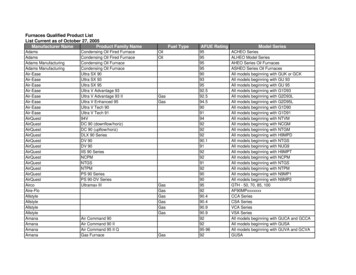
OUTDOOR UNIT INSTALLATION2.1Precautions for selecting the location1) Choose a place solid enough to bear the weight and vibration ofthe unit, where the operation noise will not be amplified.2) Choose a location where the hot air discharged from the unit orthe operation noise will not cause a nuisance to the neighboursof the user.3) Avoid places near a bedroom and the like, so that the operationnoise will cause no trouble.4) There must be sufficient spaces for carrying the unit into and outof the site.5) There must be sufficient space for air passage and noobstructions around the air inlet and the air outlet.6) The site must be free from the possibility of flammable gasleakage in a nearby place.7) Install units, power cords and inter-unit wire at least 3m away fromtelevision and radio sets. This is to prevent interference to imagesand sounds. (Noises may be heard even if they are more than 3maway depending on radio wave conditions.)8) In coastal areas or other places with salty atmosphere of sulfategas, corrosion may shorten the life of the air conditioner.9) Since drain flows out of the outdoor unit, do not place under theunit anything which must be kept away from moisture.ABFUnit:mmMODELNOTE:ECD2.Figure of body sizeH2.29K 18KCannot be installed hanging from ceiling or stacked.A780760810845(in mm/25.4)CAUTIONWhen operating the air conditioner in a low outdoor ambienttemperature, be sure to follow the instructions described below.- To prevent exposure to wind, install the outdoor unit with its suctionside facing the wall.- Never install the outdoor unit at a site where the suction side maybe exposed directly to wind.- To prevent exposure to wind, it is recommended to install a baffleplate on the air discharge side of the outdoor unit.- In heavy snowfall areas, select an installation site where the snowwill not affect the unit.- Construct a large canopy.- Construct a pedestal.Install the unit high enough off theground to prevent burying in 70305312F250285310320H540590558700
2.4 Outdoor unit installation2.3 Installation guidelinesWhere a wall or other obstacle is in the path of outdoor unit'sinlet or outlet airflow, follow the installation guidelines below.1) Installing outdoor unitWhen installing the outdoor unit, refer to "Precautions forselecting the location" .For any of the below installation patterns, the wall height on theoutlet side should be 1200mm/47.2in or less.Check the strength and level of the installation ground so thatthe unit will not cause any operating vibration or noise afterinstalled.Wall facing one sideMore than 100Fix the unit securely by means of the foundation bolts.(Prepare 4 sets of M8 or M10 foundation bolts, nuts andwashers each which are available on the market.)More than 350Directionof air1200or lessSide viewFix with boltsWalls facing two sidesMorethan 100Morethan 3502) Drain workMore than 50More than 50If drain work is necessary, follow the procedures below.Top viewUse drain plug for drainage.If the drain port is covered by a mounting base or floor surface,place additional foot bases of at least 30mm/1.2in in height underthe outdoor unit's feet.Walls facing three sidesIn cold areas, do not use a drain hose with the outdoor unit.(Otherwise, drain water may freeze, impairing heatingperformance.)More than 100Drain portMore than 350Bottom frameMore than 50Unit:mmTop view(in mm/25.4)8SealDrain plugHose
3INSTALL THE REFRIGERANT PIPE3.1 Flaring the pipe end1) Cut the pipe end with a pipe cutter.All field piping must be provided by a licensed refrigerationtechnician and must comply with the relevant local andnational codes.2) Remove burrs with the cut surface facing downward so that thechips do not enter the pipe.PrecautionsCut exactly atright angles.Execute heat insulation work completely on both sides of thegas piping and liquid piping. Otherwise, this can sometimesresult in water leakage.(When using a heat pump, the temperature of the gas piping canreach up to approximately 120 /248OF. Use insulation which issufficiently resistant.)Remove burrs.3) Put the flare nut on the pipe.4) Flare the pipe.(in mm/25.4)A(mm)Outer diam.(mm)Max.Min.O6.35 (1/4 in)1.30.7O9.52 (3/8in)1.61.0O12.7 (1/2in)1.81.0O15.9 (5/8in)2.22.0Set exactly at the position shown below.AAlso, in cases where the temperature and humidity of therefrigerant piping sections might exceed 30 /86OF or Rh80%,reinforce the refrigerant insulation(20mm/0.8in or thicker).Condensation may form on the surface of the insulating material.Before rigging tubes, check which type of refrigerant is used.Use a pipe cutter and flare suitable for used refrigerant.DieCopper pipeOnly use annealed material for flare conncetions.Do not mix anything other than the specified refrigerant, suchas air, etc., Inside the refrigerant circuit.5) Check that the flaring is properly made.If the refrigerant gas leaks during the work, ventilate the area.A toxic gas is emitted by the refrigerant gas being exposed toa fire.The pipe end mustbe evenly flared in aperfect circle.Flare's inner surfacemust be flaw-freeMake sure there is no refrigerant gas leak. A toxic gas may bereleased by the refrigerant gas leaking indoor and beingexposed to flames from an area heater, cooking stove, etc.Make sure that theflare nut is fitted.Refer to the table below for the dimensions of flare nuts spacesand the appropriate tightening torque. (Overtightening maydamage the flare and cause leaks.)Pipe gaugeFlare dimensionFlare shapeTightening torque(mm)A (mm)15 16 N. m8.3 8.7O 6.35(1/4 in) (153 163 kgf.cm)90 40.327 0.343ino25 26 N. mO 9.52(3/8in) (255 265 kgf.cm)12.0 12.40.472 0.488in35 36 N. mO 12.7(1/2in) (357 367 kgf.cm)15.4 15.80.606 0.622in45 47 N. m(459 480 kgf.cm)18.6 19.00.732 0.748inO 15.9(5/8in)45Ao23.2 Refrigerant pipingCoat the flare both inside and ouside with ether oil or ester oil .R0.4 0.80.016 0.031inCoat here with ether oil or ester oilCheck whether the height drop between the indoor unit andoutdoor unit, and the length of refrigerant pipe meet the followingrequirements:The type of modelsCapacity(Btu/h)T1 conditionSplit type air conditioner9K 12KR410A inverterSplit type air conditioner9K 12K18K18KT3 condition(outdoor unit down)9K 12KT3 condition(outdoor unit up)9K 12K18K18KMax.allowable Max.allowablepiping lengthpiping /65.6ftAlign the centres of both flares and tighten the flare nuts 3 or 4turns by hand. Then tighten them fully with the torque wrenches.12341923 4Torque wrenchFlare nutPiping unionSpanner
3.3 Installation of the throttle. (For some models)5/1900mm3.4 Purging air and checking gas leakageWhen piping work is completed, it is necessary to purge theair and check for gas leakage.7inWARNINGDo not mix any substance other than the specified refrigerantinto the refrigeration cycle.When refrigerant gas leaks occur, ventilate the room as soon aspossible.The specified refrigerant should always be recovered and neverbe released directly into the environment.Use a vacuum pump for the specified refrigerant. Using thesame vacuum pump for different refrigerants may damage thevacuum pump or the unit.123123ThrottleLiquid pipeGas pipeIf using additional refrigerant, perform air purging from therefrigerant pipes and indoor unit using a vacuum pump, thancharge additional refrigerant.Use a hexagonal wrench(4mm/0.2in) to operate the stop valverod.All refrigerant pipe joints should be tightened with a torquewrench at the specified tightening torque.Precautions- For ensuring throttled efficiency, please mount the throttleas horizontally as possible.IndoorOutdoorOutdoorIndoor1) Connect projection side of charging hose (which comes fromgauge manifold) to gas stop valve's service port.2) Full open gauge manifold's low-pressure valve (Lo) andcompletely close its high-pressure valve (Hi)(High-pressure valve subsequently requires no operation.)3) Do vacuum pumping and make sure that the compoundpressure gauge reads -0.1MPa (-76cmHg).*14) Close gauge manifold's low-pressure valve (Lo) and sopvacuum pump.(Keep this state for a few minutes to make sure that thecompound pressure gauge pointer does not swing back.)*25) Remove caps from liquid stop valve and gas stop valve.6) Turn the liquid stop valve's rod 90 degrees counterclockwisewith a hexagonal wrench to open valve.Close it after 5 seconds, and check for gas leakage.Using soapy water, check for gas leakage from indoor unit'sflare and outdoor unit's flare and valve rods.After the check is complete, wipe all soapy water off.7) Disconnect charging hose from gas stop valve's service portthen fully open liquid and gas stop valves.(Do not attempt to turn valve rod byond its stop.)8) Tighten valve caps and service port caps for the liquid andgas stop valves with a torque wrench at the specified torques.IndoorOutdoor-Wrap the supplied anti-shock rubber at external of thethrottle for denoise.12Anti-shock rubberThrottle*1. Pipe length vs. Vacuum pump run time10
Pipe lengthUp to 15m/49.2ftRun timeNot less than 10 minMore than 15m/49.2ft2) Be sure to insulate both the gas and liquid piping. Useseparate thermal insulation pipes for gas and liquidrefrigerant pipes. See the figure below.Not less than 15min*2. If the compound pressure gauge pointer swings back,refrigerant may have water content or a loose pipe joint mayexists. Check all pipe joints and retighten nuts as needed,then repeat steps 2) through 4).Inter-unit wireGas pipe3.5 Additional refrigerant chargeLiquid pipeLiquid pipeinsulationGas pipeinsulationDrain hoseFinishing tapeCAUTIONRefrigerant may only be charged after performing the leaktest and the vacuum pumping.Check the type of refrigerant to be used on the machinenameplate. Charging with an unsuitable refrigerant maycause explosions and accidents, so always ensure that theappropriate refrigerant is charged.Refrigerant containers shall be opened slowly.3) Finally, insulate as shown in the figure below.123456The outdoor unit is factory charged with refrigerant. Calculate theadded refrigerant according to the diameter and the length of theliquid pipe of the outdoor unit/indoor unit connection.536Liquid pipeGas pipeInsulation for liquid pipe fittingInsulation for gas pipe fittingClamps(use 2 clamps per insulation)Indoor unit1Pipe length and refrigerant amount:Connectivepipe lengthAir purgingmethodLessthan 7.5mUse vacuumpump.24Additional amount of refrigerant to be chargedPiping insulation procedureLiquid side: 6.35mm / 1/4inMorethan 7.5mUse vacuumR410A: (Pipe length-7.5(25))x15g/m(0.16oz/ft)pump.Gas pipingLiquid side: 9.52mm / 3/8in:R410A: (Pipe length-7.5(25))x30g/m(0.32oz/ft)1632Liquid piping64516 32645Be sure to add the proper amount of additional refrigerant.Failure to do so may result in reduced performance.A3.6 Refrigerant pipig work1) Caution on the pipe handlingProtect the open end of the pipe against dust and moisture.All pipe bends should be as gentle as possible. Use a pipebender for bending.RainWallBe sure toplace a cap.CBAC123456Piping insulation material(field supply)Flare nut connectionInsulation for fitting (field supply)Piping insulation material (main unit)Indoor unitClamp (field supply)ABCTurn seams upAttach to baseTighten the part other than the piping insulation materialBFor local insulation, be sure to insulate local pipingall the way into the pipe connections inside the unit.Exposed piping may cause condensation or maycause burns when touched.If no flare cap isavailable, cover theflare mouth withtape to keep dirt orwater out.Make sure that no oil remains on plastic parts of thedecoration panel (optional equipment).Oil may cause degradation and damage to plasticparts.11
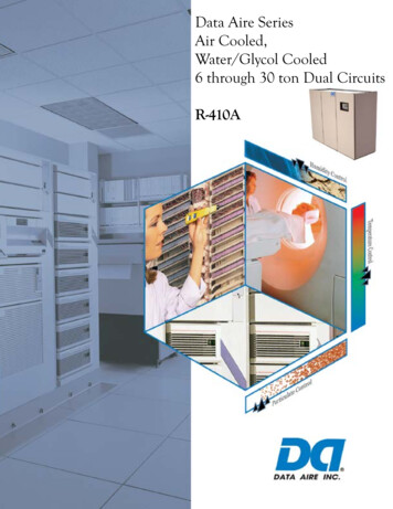
4CONNECT THE DRAIN PIPE4.3 How to perform piping4.1 Installation of drain piping1536 514750/29.5in2220/8.7in Ў530/20.9in1-1.5m3 5ft300/11.8in0 750 3inInstall the drain piping as shown in figure below and take measuresagainst condensation. Improperly rigged piping could lead to leaksand eventually wet furniture and belongings.1 1.5m3 5ft2Unit: mm12345612Ceiling slabHanger bracketAdjustable rangeDrain raising pipeDrain hoseMetal clamp- Connect the drain hose to the drain raising pipes, andinsulate them.- Connect the drain hose to the drain outlet on the indoor unit,and tighten it with the clamp.Hanging bar1/100 gradient4.2 Install the drain pipes.- Keep piping as short as possible and slope it downwards at agradient of at least 1/100 so that air may not remain trappedinside the pipe.- Keep pipe size equal to or greater than that of the connectingpipe (PVC pipe, nominal diameter 20mm/0.8in in, outsidediameter 25mm/1in).- Push the drain hose as far as possible over the drain socket,and tighten the metal clamp securely.0-530Precautions- Install the drain raising pipes at a height of less than 530 mm/20.9 in.- Install the drain raising pipes at a right angle to the indoorunit and no more than 300 mm/11.8 in from the unit.- To prevent air bubbles, install the drain hose level or slightlytilted up ( 75 mm/3 in).- The incline of drain hose should be 75 mm/3 in or less sothat the drain socket does not have to withstand additional force.- To ensure a downward slope of 1:100, install hangingbars every 1m/3.3ft to 1.5 m/4.9ft.- When unifying multiple drain pipes, install the pipes asshown in figure below. Select converging drain pipes whosegauge is suitable for the operating
FOUR-WAY CASSETTE AB SERIES, HEAT PUMP INSTALLATION MANUAL FOR MODELS: 2PAMSCH09 2PAMSCH12 2PAMSCH18 MULTI-ZONE . (Refer to the installation manual of the outdoor unit.) - Keep indoor unit,outdoor unit,inter unit wiring and remote controller wiring at least 1 meter away from televisions and