Transcription
X8DTN X8DTN -LRUSER’S MANUALRevision 1.2
The information in this User’s Manual has been carefully reviewed and is believed to be accurate.The vendor assumes no responsibility for any inaccuracies that may be contained in this document,makes no commitment to update or to keep current the information in this manual, or to notify anyperson or organization of the updates. Please Note: For the most up-to-date version of thismanual, please see our website at www.supermicro.com.Super Micro Computer, Inc. ("Supermicro") reserves the right to make changes to the productdescribed in this manual at any time and without notice. This product, including software and documentation, is the property of Supermicro and/or its licensors, and is supplied only under a license.Any use or reproduction of this product is not allowed, except as expressly permitted by the termsof said license.IN NO EVENT WILL SUPER MICRO COMPUTER, INC. BE LIABLE FOR DIRECT, INDIRECT,SPECIAL, INCIDENTAL, SPECULATIVE OR CONSEQUENTIAL DAMAGES ARISING FROM THEUSE OR INABILITY TO USE THIS PRODUCT OR DOCUMENTATION, EVEN IF ADVISED OFTHE POSSIBILITY OF SUCH DAMAGES. IN PARTICULAR, SUPER MICRO COMPUTER, INC.SHALL NOT HAVE LIABILITY FOR ANY HARDWARE, SOFTWARE, OR DATA STORED OR USEDWITH THE PRODUCT, INCLUDING THE COSTS OF REPAIRING, REPLACING, INTEGRATING,INSTALLING OR RECOVERING SUCH HARDWARE, SOFTWARE, OR DATA.Any disputes arising between manufacturer and customer shall be governed by the laws of SantaClara County in the State of California, USA. The State of California, County of Santa Clara shall bethe exclusive venue for the resolution of any such disputes. Supermicro's total liability for all claimswill not exceed the price paid for the hardware product.FCC Statement: This equipment has been tested and found to comply with the limits for a ClassA digital device pursuant to Part 15 of the FCC Rules. These limits are designed to providereasonable protection against harmful interference when the equipment is operated in a commercialenvironment. This equipment generates, uses, and can radiate radio frequency energy and, if notinstalled and used in accordance with the manufacturer’s instruction manual, may cause harmfulinterference with radio communications. Operation of this equipment in a residential area is likelyto cause harmful interference, in which case you will be required to correct the interference at yourown expense.California Best Management Practices Regulations for Perchlorate Materials: This Perchloratewarning applies only to products containing CR (Manganese Dioxide) Lithium coin cells. “PerchlorateMaterial-special handling may apply. See ING: Handling of lead solder materials used in thisproduct may expose you to lead, a chemical known tothe State of California to cause birth defects and otherreproductive harm.Manual Revision 1.2Release Date: Jan. 27, 2012Unless you request and receive written permission from Super Micro Computer, Inc., you may notcopy any part of this document.Information in this document is subject to change without notice. Other products and companiesreferred to herein are trademarks or registered trademarks of their respective companies or markholders.Copyright 2012 by Super Micro Computer, Inc.All rights reserved.Printed in the United States of America
PrefacePrefaceAbout This ManualThis manual is written for system integrators, PC technicians and knowledgeable PCusers. It provides information for the installation and use of theX8DTN /X8DTN -LR motherboard.About This MotherboardTheX8DTN /X8DTN -LR supports the Intel 5500/5600 Series Processors, the first dual-processing platform that offers Intel QuickPath Interconnect(QPI) Technology to provide the next generation point-to-point system interface,replacing the current Front Side Bus. With the 5500/5600 Series Processors builtin, the X8DTN /X8DTN -LR substantially enhances system performance with increased bandwidth and unprecedented scalability. This motherboard is optimizedfor intensive-applications and high-end servers. Please refer to our web site (http://www.supermicro.com/products/) for processor and memory support updates. Thisproduct is intended to be installed and serviced by a professional technician.Manual OrganizationChapter 1 describes the features, specifications and performance of the motherboard and provides detailed information about the 5520 chipset.Chapter 2 provides hardware installation instructions. Read this chapter when installing the processor, memory modules and other hardware components into thesystem. If you encounter any problems, see Chapter 3, which describes troubleshooting procedures for video, memory and system setup stored in the CMOS.Chapter 4 includes an introduction to the BIOS and provides detailed informationon running the CMOS Setup utility.Appendix A lists BIOS POST Error Codes. Appendix B provides Software Installation Instructions.Conventions Used in the ManualSpecial attention should be given to the following symbols for proper installation andto prevent damage done to the components or injury to yourself:Warning: Important information given to ensure proper system installationor to prevent damage to the components.iii
X8DTN /X8DTN -LR User's ManualNote: Additional Information given to differentiate various models or toensure correct system setup.iv
Table of ContentsContacting SupermicroHeadquartersAddress:Super Micro Computer, Inc.980 Rock Ave.San Jose, CA 95131 U.S.A.Tel: 1 (408) 503-8000Fax: 1 (408) 503-8008Email:marketing@supermicro.com (General Information)support@supermicro.com (Technical Support)Web Site:www.supermicro.comEuropeAddress:Super Micro Computer B.V.Het Sterrenbeeld 28, 5215 ML's-Hertogenbosch, The NetherlandsTel: 31 (0) 73-6400390Fax: 31 (0) 73-6416525Email:sales@supermicro.nl (General Information)support@supermicro.nl (Technical Support)rma@supermicro.nl (Customer Support)Asia-PacificAddress:Super Micro Computer, Inc.4F, No. 232-1, Liancheng Rd.Chung-Ho 235, Taipei CountyTaiwan, R.O.C.Tel: 886-(2) 8226-3990Fax: 886-(2) 8226-3991Web .com.tw (Technical Support)Tel: 886-(2) 8226-5990 (Technical Support)v
X8DTN /X8DTN -LR User's ManualTable of ContentsPrefaceChapter 1 Introduction.1-11-1Overview. 1-11-2Processor and Chipset Overview.1-111-3Special Features. 1-121-4PC Health Monitoring. 1-121-5ACPI Features. 1-131-6Power Supply. 1-131-7Super I/O. 1-14Chapter 2 Installation.2-12-1Static-Sensitive Devices. 2-1Precautions. 2-1Unpacking. 2-12-2Processor and Heatsink Installation. 2-2Installing a CPU Heatsink. 2-42-3Mounting the Motherboard into the Chassis. 2-6Tools Needed. 2-6Installation Instructions. 2-62-4Installing and Removing the Memory Modules. 2-7Installing & Removing DIMMs. 2-72-5Control Panel Connectors/IO Ports. 2-131. Back Panel Connectors/IO Ports. 2-132. Back Panel IO Port and Onboard IO Connection Pin Definitions. 2-14ATX PS/2 Keyboard and PS/2 Mouse Ports. 2-14Universal Serial Bus (USB). 2-15Serial Ports. 2-16VGA Connector. 2-17Gigabit LAN (Ethernet) Ports. 2-183. Front Control Panel. 2-194. Front Control Panel Pin Definitions. 2-20NMI Button. 2-20Power LED . 2-20HDD LED. 2-212-6Connecting Cables. 2-24Processor Power Connector . 2-24Internal Speaker. 2-26vi
Table of ContentsOverheat LED/Fan Fail (JOH1). 2-26Compact Flash Card PWR Connector. 2-292-7Jumper Settings. 2-31Explanation of Jumpers. 2-31CMOS Clear. 2-32Watch Dog Enable/Disable. 2-32VGA Enable/Disable. 2-332-8Onboard Indicators. 2-352-9Floppy Drive, SIMLP, Serial ATA and HDD Connections. 2-36Serial ATA Ports. 2-37SIMLP IPMI Slot. 2-37Chapter 3 Troubleshooting.3-13-1Troubleshooting Procedures. 3-1Before Power On. 3-1No Power. 3-1No Video. 3-2Losing the System’s Setup Configuration. 3-2Memory Errors . 3-23-2Technical Support Procedures. 3-33-3Frequently Asked Questions. 3-33-4Returning Merchandise for Service. 3-4Chapter 4 BIOS .4-14-1Introduction. 4-1Starting BIOS Setup Utility. 4-1How To Change the Configuration Data. 4-2Starting the Setup Utility. 4-24-2Main Setup. 4-24-3Advanced Setup Configurations. 4-44-4Security Settings. 4-234-5Boot Configuration. 4-244-6Exit Options. 4-26Appendix A BIOS Error Beep Codes . A-1A-1BIOS Error Beep Codes.A-1Appendix B Software Installation Instructions . B-1B-1Installing Software Programs.B-1B-2Configuring Supero Doctor III Settings.B-2vii
X8DTN /X8DTN -LR User's ManualNotesviii
Chapter 1: IntroductionChapter 1Introduction1-1OverviewChecklistCongratulations on purchasing your computer motherboard from an acknowledgedleader in the industry. Supermicro boards are designed with the utmost attention todetail to provide you with the highest standards in quality and performance. Checkthat the following items have all been included with your motherboard. If anythinglisted here is damaged or missing, contact your retailer.The following items are included in the retail box. One (1) Supermicro Mainboard One (1) ribbon cable for IDE devices (CBL-0036L-03) One (1) floppy ribbon cable (CBL-0022L) One (1) COM-port cable (CBL-010L) One (1) 2-port USB 2.0 cable (CBL-0083L) Six (6) Serial ATA cables (CBL-0044Lx6) One (1) I/O backpanel shield (CSE-PT07L) One (1) Supermicro CD containing drivers and utilities One (1) User's/BIOS Manual1-1
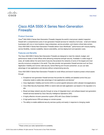
X8DTN /X8DTN -LR User's ManualX8DTN /X8DTN -LR ImageNote: The drawings and pictures shown in this manual were based on thelatest PCB Revision available at the time of publishing of the manual. Themotherboard you’ve received may or may not look exactly the same asthe graphics shown in the manual.1-2
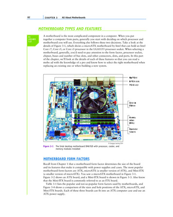
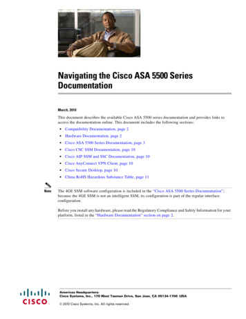
Chapter 1: IntroductionX8DTN /X8DTN -LR Motherboard LayoutP1 DIMM3AFan5PWR I2C Fan7CPU2 FanP1 DIMM3BJPW1 JPW4JPW3P1 DIMM2CCPU2P1 DIMM1AP1 DIMM1BJF1LAN1LAN2JWDCPU1FanSIMLP IPMIJD1 LE1P2 DIMM1CP2 DIMM1BP2 DIMM1AP2 DIMM2COH LEDJOH1VGAJ108 J107 J106 J105 J104 J103 J102 J101 J100Fan2COM1P1 DIMM1CCPU1Fan8Fan1JPP1JPP0JP6P1 DIMM2AP1 DIMM2BFP CTRLUSB0/1 KB/MSFan6XDPP1 DIMM3CP2 DIMM2BP2 DIMM2AP2 DIMM3CP2 DIMM3BP2 DIMM3AFan3SEPC J11Clear CMOSJBT1Intel 5520BatteryJI2C1SPISlot4 PCI-E2.0 X8JWOL1JP5 JP7BIOSSlot3 PCI-X 133MHZLANCTRLIntel ICH10R(South Bridge)PXHSlot2 PCI-X 100/133MHZJPL1IDEJI2C2(North Bridge)FloppyRev. 2.0Slot5 PCI-E X41-3I-SATA1I-SATA0TPM HeaderI-SATA2JL1USB2/3I-SATA3T-SGPIO2JWOR1 IPMBUSB7JTPM1Slot0 1 PCI-X 100/133MHZS I/OUSB4X8DTN SPKRSlot6 PCI-E2.0 X8VGACTRLFan4JP3
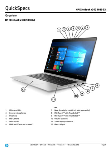
X8DTN /X8DTN -LR User's ManualX8DTN /X8DTN -LR Quick ReferenceP1 DIMM3AFan5PWR I2C Fan7CPU2 FanP1 DIMM3BJPW1 JPW4JPW3P1 DIMM2CCPU2P1 DIMM1AP1 DIMM1BJF1LAN1LAN2JWDCPU1FanSIMLP IPMIJD1 LE1P2 DIMM1CP2 DIMM1BP2 DIMM1AP2 DIMM2COH LEDJOH1VGAJ108 J107 J106 J105 J104 J103 J102 J101 J100Fan2COM1P1 DIMM1CCPU1Fan8Fan1JPP1JPP0JP6P1 DIMM2AP1 DIMM2BFP CTRLUSB0/1 KB/MSFan6XDPP1 DIMM3CP2 DIMM2BP2 DIMM2AP2 DIMM3CP2 DIMM3BP2 DIMM3AFan3SEPC J11Clear CMOSJBT1Intel 5520BatteryJI2C1SPISlot4 PCI-E2.0 X8JWOL1JP5 JP7BIOSSlot3 PCI-X 133MHZLANCTRLIntel ICH10R(South Bridge)PXHSlot2 PCI-X 100/133MHZJPL1IDEJI2C2(North Bridge)FloppyRev. 2.0Slot5 PCI-E X4I-SATA1I-SATA0TPM HeaderI-SATA2JL1USB2/3I-SATA3T-SGPIO2JWOR1 IPMBUSB7JTPM1Slot0 1 PCI-X 100/133MHZS I/OUSB4X8DTN SPKRSlot6 PCI-E2.0 X8VGACTRLFan4JP3Notes:1. Jumpers not indicated are for internal testing only.2. See Chapter 2 for detailed information on jumpers, I/O ports and JF1front panel connections.3. " " indicates the location of Pin 1.4. When LE1 LED is on, the onboard power connection is on. Make sureto unplug the power cables before removing or installing components.Warning! 1.To prevent damage to your power supply or motherboard,please use a power supply that contains a 24-pin and two 8-pin powerconnectors. Be sure to connect these power connectors to the 24-pin andthe two 8-pin power connectors on your motherboard for adequate powersupply to your system. Failure to do so will void the manufacturer warrantyon your power supply and motherboard.2. To avoid possible system overheating, be sure to provide adequateairflow to the system.1-4
Chapter 1: IntroductionX8DTN /X8DTN -LR Quick ReferenceJumperDescriptionDefault SettingJBT1CMOS Clear(See Section 5-10)JWDWatch Dog EnablePins 1-2 (Reset)JI C1/JI C2SMB to PCI-Exp./ SMB to PCI-X SlotsOpen (Disabled)JP3IDE Enable1-2 (Normal)JPG1VGA Enable1-2 (Enable)JPL1LAN1/2 EnablePins 1-2 (Enabled)22ConnectorDescriptionCOM1/COM2COM1/COM2 Serial Port/HeaderFAN 1-8System/CPU Fan Headers (Fans 7/8: CPU Fans)FloppyFloppy Disk Drive ConnectorIPMB (J14)IPMB I2C Header (for an IPMI card)I-SATA0 I-SATA5(Intel South Bridge) SATA PortsJD1PWR LED/Speaker Header (Pins1 3: PWR LED, 4 7: SPKR)JF1Front Panel ConnectorJL1Chassis Intrusion HeaderJOH1Overheat LED HeaderJPW124-pin ATX Main Power Connector (Required)JPW3/JPW48-pin 12-V Power Connectors (Required. See Page1-4)JTPM1TPM (Trusted Platform Module) HeaderJWF1Compact Flash Power ConnectorJWOL1Wake-On-LAN HeaderLAN1/2Gigabit Ethernet (RJ45) PortsPWR I2C (J15)Power SMB (I2C) HeaderSIMLP(Low Profile) SIMLP IPMI 2.0 SocketSP1Internal BuzzerT-SGPIO-1/T-SGPIO-2Serial General Purpose Input/Output Headers(B/P) USB0/1(Back Panel) Universal Serial Bus (USB) Ports(F/P) USB 2/3, 4, 6, 7Front Panel Accessible USB HeadersLEDDescriptionLE1Onboard Standby PWR warning LED Indicator1-5
X8DTN /X8DTN -LR User's ManualMotherboard FeaturesCPU Two Intel 5500/5600 Series (LGA 1366) processors, each processor supportingtwo full-width Intel QuickPath Interconnect (QPI) links with a total of up to 51.2GB/s Data Transfer Rate (6.4 GB/s per direction)Memory RDIMM 240-pin Reg. DDR3 ECC 1333/1066/800 MHz memory with support of upto 288 GB in 18 slotsNote 1. 240-pin Dual Rank (DR) 16 GB Reg. ECC DDR3 1333/1066/800MHz memory will support up to 288 GB. Memory speed will be downgradedto 800 MHz. (Refer to the notes in the memory configuration tables inChapter 2.)Note 2. 240-pin Quad Rank (QR) 16 GB Reg. ECC DDR3 1066/800 MHzmemory will support up to 192 GB (with 6 DIMMs max. per CPU). Memoryspeed will be downgraded to 800 MHz. (Refer to the notes in memoryconfiguration tables in Chapter 2.) LRDIMM (Load Reduced DIMM, for X8DTN -LR Only) LRDIMM DDR3 ECC 1066 MHz memory with support of up 288 GB in 18slotsWarning: For your system memory to work properly, be sure to use thecorrect BIOS ROM for your system. For the X8DTN , use the X8DTN BIOS. For the X8DTN -LR, use the X8DTN -LR BIOS. To flash the BIOS,refer to /5500/X8DTN .cfm?IPMI Y. UDIMMUnbuffered ECC/Non-ECC DDR3 1333/1066/800 MHz memory of up to 48 GBmemoryChipset Intel 5520 chipset, including: the 5520 (North Bridge) and the ICH10R (SouthBridge).Expansion Slots Two PCI-E 2.0 x8 slot (Slot4/Slot6)One PCI-E x4 (in x8 slot) (Slot5)Two PCI-X 100MHz/133MHz slots (Slot2/Slot3)1-6
Chapter 1: Introduction One PCI-X 133MHz slots (Slot1)One PCI-U (UIO) Slot (Slot0)SEPC (Supermicro PCI-E Power Connector) Slot (J11)One SIMLP IPMI SlotBIOS 32 Mb AMI SPI Flash ROMPCI 2.2, ACPI 1.0/2.0/3.0, Plug and Play (PnP), DMI 2.3, USB Keyboard support, and SMBIOS 2.3PC Health Monitoring Onboard voltage monitors for CPU1 Vcore, CPU2 Vcore, 5Vin, 12V, -12V3.3Vcc (V), and Battery Voltage Fan status monitor with firmware controlCPU/chassis temperature monitorsPlatform Environment Control Interface (PECI) readyThermal Monitor 2 (TM2) supportCPU fan auto-off in sleep modeCPU slow-down on temperature overheatPulse Width Modulation (PWM) Fan ControlCPU thermal trip support for processor protection, power LEDPower-up mode control for recovery from AC power lossAuto-switching voltage regulator for CPU coresSystem overheat/Fan Fail LED Indicator and controlChassis intrusion detectionSystem resource alert via Supero Doctor IIIACPI Features Slow blinking LED for suspend state indicatorMain switch override mechanismACPI Power ManagementOnboard I/O Intel ICH10R supports six SATA2 ports (with RAID0, RAID1, RAID10, RAID5supported in the Windows OS Environment) One SIMLP IPMI socket One EIDE Ultra DMA/100 bus master interfaceIntel 82576 dual-LAN Gigabit Ethernet controller supports dual Giga-bit LANportsOne floppy port interface1-7
X8DTN /X8DTN -LR User's Manual Two COM ports(1 header, 1 port) Super I/O: Winbond W83627HFPS/2 mouse and PS/2 keyboard portsUp to seven USB 2.0 (Universal Serial Bus) (2 Ports, 2 Front Headers, and 2Type A Headers)ATI ES1000 32Mb VGA Controller supports one VGA portOther Console redirectionOnboard Fan Speed Control by Thermal Management via BIOSCD/Diskette Utilities BIOS flash upgrade utility and device driversDimensions Ext. ATX 13.68" (L) x 13" (W) (347.47 mm x 330.20 mm)1-8
Chapter 1: IntroductionNotes1-9
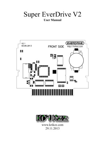
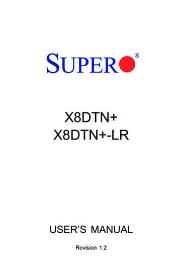
X8DTN /X8DTN -LR User's ManualC#3B CPU1PCI-E x8 SlotJ10#0J3#1PCI-X SlotJ2#2PCI-X SlotJ1#3PCI-Ex16 rts2,1#2#2#2DEF#1#1#182576Intel 5520J11#3DDR3 DIMMBADDR3 DIMMC#3#3DDR3 DIMMBASEPC PCI-E x8 SlotDDR3 DIMM#2#2DDR3 DIMM#2ARJ45RJ45Ports5,6Ports7,8 Ports ESI CLINK9,10Chnl ASST25PXHVF016Chnl BSPIx1JMB368ICH10RPE4-1SATASIMLPPCIDDR2IDEDMI CLINKPE5J5#5 x4PCI-E x8 SlotPCI-X SlotDDR3 DIMM#1#1#1VGAES1000SATA #1SATA #2SATA #3SATA #4SATA #5SATA #6LPCSIO83627FloppyVGABlock Diagram of the 5520 PlatformNote: This is a general block diagram. Please see the previous Motherboard Features pages for details on the features of each motherboard.1-10
Chapter 1: Introduction1-2Processor and Chipset OverviewBuilt upon the functionality and the capability of the 5500/5600 Series Processorplatform, the X8DTN /X8DTN -LR motherboard provides the performance andfeature set required for dual-processor-based high-end systems with configurationoptimized for intensive application and high-end server platforms. The 5500/5600Series Processor platform consists of the 5500/5600 Series (LGA 1366) processor, the 5520 (North Bridge), and the ICH10R (South Bridge). With the IntelQuickPath Interconnect (QPI) controller built in, the 5500/5600 Series Processorplatform is the first dual-processing platform to offer the next generation pointto-point system interconnect interface that replaces the current Front Side BusTechnology and substantially enhances system performance by utilizing serial linkinterconnections, allowing for increased bandwidth and scalability.The 5520 connects to each processor through an independent QuickPath Interconnect link. Each link consists of 20 pairs of uni-directional differential lanes fortransmission and receiving in addition to a differential forwarded clock. A full-widthQPI link pair provides 84 signals. Each processor supports two QuickPath link,one going to the other processor and the other to the 5520.The 5520 supports up to 36 PCI Express Gen2 lanes, peer-to-peer read and writetransactions. The ICH10R supports up to 6 PCI-Express ports, six SATA portsand 10 USB connections.In addition, the 5500/5600 Series Processor platform also offers a wide range ofRAS (Reliability, Availability and Serviceability) features. These features includememory interface ECC, x4/x8 Single Device Data Correction (SDDC), Cyclic Redundancy Check (CRC), parity protection, out-of-band register access via SMBus,memory mirroring, and Hot-plug support on the PCI-Express Interface. The Main Features of the 5500/5600 Series Processor andthe 5520 ChipsetFour processor cores in each processor with 8MB shared cache among coresTwo full-width Intel QuickPath interconnect links, up to 6.4 GT/s of data transferrate in each directionVirtualization Technology, Integrated Management Engine supportedPoint-to-point cache coherent interconnect, Fast/narrow unidirectional links, andConcurrent bi-directional trafficError detection via CRC and Error correction via Link level retry1-11
X8DTN /X8DTN -LR User's Manual1-3Special FeaturesRecovery from AC Power LossBIOS provides a setting for you to determine how the system will respond whenAC power is lost and then restored to the system. You can choose for the systemto remain powered off (in which case you must hit the power switch to turn it backon) or for it to automatically return to a power- on state. See the Advanced BIOSSetup section to change this setting. The default setting is Last State.1-4PC Health MonitoringThis section describes the PC health monitoring features of the X8DTN /X8DTN LR. All have an onboard System Hardware Monitor chip that supports PC healthmonitoring. An onboard voltage monitor will scan these onboard voltages continuously: CPU1 Vcore, CPU2 Vcore, 5Vin, 12V, -12V 3.3Vcc (V), and Battery Voltage. Once a voltage becomes unstable, a warning is given or an error message issent to the screen. Users can adjust the voltage thresholds to define the sensitivityof the voltage monitor.Fan Status Monitor with Firmware ControlThe PC health monitor can check the RPM status of the cooling fans. The onboardCPU and chassis fans are controlled by Thermal Management via BIOS (underHardware Monitoring in the Advanced Setting).Environmental Temperature ControlThe thermal control sensor monitors the CPU temperature in real time and will turnon the thermal control fan whenever the CPU temperature exceeds a user-definedthreshold. The overheat circuitry runs independently from the CPU. Once it detectsthat the CPU temperature is too high, it will automatically turn on the thermal fancontrol to prevent any overheat damage to the CPU. The onboard chassis thermalcircuitry can monitor the overall system temperature and alert users when the chassis temperature is too high.Warning! To avoid possible system overheating, be sure to provide adequate airflow to the system.System Resource AlertThis feature is available when used with Supero Doctor III in the Windows OSenvironment or used with Supero Doctor II in Linux. Supero Doctor is used to1-12
Chapter 1: Introductionnotify the user of certain system events. For example, you can also configureSupero Doctor to provide you with warnings when the system temperature, CPUtemperatures, voltages and fan speeds go beyond a pre-defined range.1-5ACPI FeaturesACPI stands for Advanced Configuration and Power Interface. The ACPI specification defines a flexible and abstract hardware interface that provides a standardway to integrate power management features throughout a PC system, includingits hardware, operating system and application software. This enables the systemto automatically turn on and off peripherals such as CD-ROMs, network cards, harddisk drives and printers.In addition to enabling operating system-directed power management, ACPIprovides a generic system event mechanism for Plug and Play and an operatingsystem-independent interface for configuration control. ACPI leverages the Plugand Play BIOS data structures while providing a processor architecture-independentimplementation that is compatible with Windows XP/Windows 2003/Windows 2008/Windows Vista Operating Systems.Slow Blinking LED for Suspend-State IndicatorWhen the CPU goes into a suspend state, the chassis power LED will start blinkingto indicate that the CPU is in suspend mode. When the user presses any key, theCPU will wake-up and the LED will automatically stop blinking and remain on.Main Switch Override MechanismWhen an ATX power supply is used, the power button can function as a systemsuspend button to make the system enter a SoftOff state. The monitor will besuspended and the hard drive will spin down. Pressing the power button againwill cause the whole system to wake-up. During the SoftOff state, the ATX powersupply provides power to keep the required circuitry in the system "alive." In casethe system malfunctions and you want to turn off the power, just press and holdthe power button for 4 seconds. This option can be set in the Power section ofthe BIOS Setup routine.1-6Power SupplyAs with all computer products, a stable power source is necessary for proper andreliable operation. It is even more important for processors that have high CPUclock rates.1-13
X8DTN /X8DTN -LR User's ManualThe X8DTN /X8DTN -LR can accommodate 24-pin ATX power supplies. Althoughmost power supplies generally meet the specifications required by the CPU, someare inadequate. In addition, the 12V 8-pin power connections are also required toensure adequate power supply to the system. Also your power supply must supply1.5A for the Ethernet ports.Warning: To prevent damage to your power supply or mother
Contacting Supermicro Headquarters Address: Super Micro Computer, Inc. 980 Rock Ave. San Jose, CA 95131 U.S.A. Tel: 1 (408) 503-8000 Fax: 1 (408) 503-8008 Email: marketing@supermicro.com (General Information) support@supermicro.com (Technical Support) Web Site: www.supermicro.com Europe Address: Super Micro Computer B.V. Het Sterrenbeeld 28 .