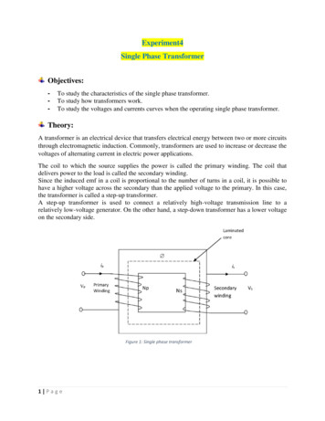
Transcription
H26564 Dissectible TransformerNFU 267PurposeThis apparatus has been designed primarily for demonstration of the basic principles of the A.C.transformer.The various coils and cores will also serve as the basis of many experiments in electromagnetism, usingeither direct or alternating current. To this end, the number of turns, the direction of winding, andthe continuous maximum rated current are marked on each coil.WarningsUsers should be aware that some combinations of coils can create dangerously highvoltages in the secondary coil, even when a low voltage power supply is used on theprimary. Such combinations must not be used.For your safety, this product should be used in accordance with these instructions, otherwise theprotection provided may be impaired.This unit is intended for use in DRY conditions. Avoid spillage of water and other liquids on to the unit.If spillage occurs, disconnect the mains or power supply.version H26564 2016
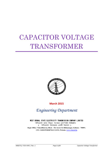
Standard ConfigurationThis is an exploded diagram of the transformer in its standard configuration – used for mostexperiments.Securing knobsClamping barYokeU-coreBase for U-coreThe U-core usually need not be removed from the base, other than for exploratory examination.Included AccessoriesAs well as the transformer assembly, the following coils are included for investigations:1 300-turn 4A2 600-turn 2A1 1200-turn 1A1 3600-turn 0.3A (centre tapped*)1 12000-turn 0.05A* some earlier units not centre tappedversion H26564 2016
The coils have two 4mm sockets for connection to a circuit. The centre-tapped coil has a third socket,connected half-way along the coil (1800 turns). Arrows on the body of the coil indicate the directionof the winding.Each coil is enclosed in the same housing, such that any two coils can be mounted on the transformerat a time (one on each side) as illustrated below.version H26564 2016
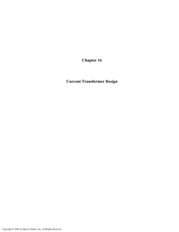
Alternative ConfigurationThe pole pieces can be used in place of the yoke. This is for experiments involving the motor accessoryset, described in NFU 453. Contact Unilab for a copy of these instructions.This is an exploded diagram of the configuration using the pole pieces. The pole pieces are secured onto the top of the armatures of the U-core by thumb screws with long threads (not illustrated).Pole piecesU-coreBase for U-coreWarningThe continuous current through the coil should not exceed the specified value for any length of time,as coils will overheat and may be irreparably damaged.version H26564 2016
ExperimentsA.C. Induction – Dependence of Induced Voltage on Coil CoreSet one 600-turn coil on the bench, with its axis horizontal, and connect a 6V A.C. power supply.Connect the other 600-turn coil to a 0-10V A.C. voltmeter. Place the second coil face-to-face with thefirst, and show that a voltage is induced across it. Vary the relative position of the two coils, in onedirection at a time to ensure it is a fair test, and note the resultant variation in induced voltage.Separate the two coils and note variation of output voltage.Connect to 6V A.C. power supply.Connect to 0-10V A.C. voltmeter.Now measure the induced voltage:1.2.3.With the laminated yoke inserted through the two coils.With both coils on the U-core.With both coils on the U-core, with the yoke clamped on.version H26564 2016
The Relationship between Transformer Input and Output Voltage WaveformsSet the two 600-turn coils on the U-core and clamp on the yoke. Connect one coil to a 12V A.C. powersupply and the other to the Y-input on an oscilloscope, with a suitably adjusted time base. Comparethe output waveform to the input one.If a dual-beam oscilloscope is available, then the input and output signals can be viewedsimultaneously for easier comparison.Connect to 12V A.C.power supplyConnect to oscilloscopeY-inputThis practical can be extended by observing the dependence on phase difference on frequency, using aPower Signal Generator to provide the input waveform.Slow A.C. experiments involve frequencies of less than 1Hz. Instead of an oscilloscope, use largedemonstration meters to observe the “lag”.If you have an oscilloscope with a trigger input, the input signal can be connected to the x-input, andanalysis of the phase different carried about by observing the Lissajous figure.version H26564 2016
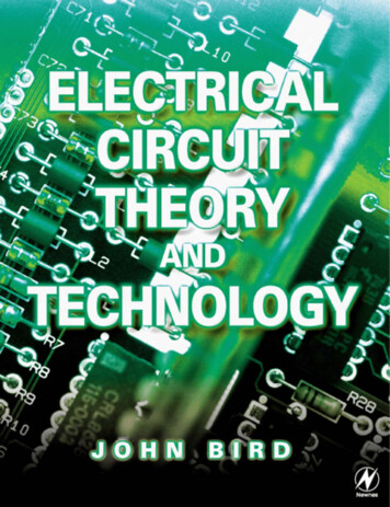
The Dependence of Transformer Output Voltage on the Turns Ratio of the Transformer CoilsUse a 600-turn coil as the primary, and use the 300, 600 and 1200 turn as the secondary, mounted onthe transformer with the yoke secured.Connect the primary to a 12V A.C. power supply, and the secondary to a multi-rangeA.C. voltmeter. Record the output voltage of each secondary coil, and plot a graph of output voltageagainst number of turns on the secondary. Note the ratio of turns of the transformer (primary tosecondary) and compare this to the ratio of input voltage to output voltage.Note: the voltmeter draws very little current from the transformer.Voltage Output per Turns on SecondaryVoltage Output (V)20.0016.0012.008.004.000.0003006009001200Number of Turns on Secondaryversion H26564 2016
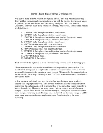
The Variation of Transformer Primary Current with Secondary CurrentSet the 1200-turn and 300-turn coils on the transformer, with the yoke secured. Connect the 1200-turncoil in series with 0.1A A.C. ammeter, and a 5V A.C. power supply. Connect the 300-turn coil with a 0135Ω 1.4A rheostat, a 0-16Ω 4A rheostat, and a 0-10A A.C. ammeter.AA135 R16 RSet the rheostats to maximum resistance before turning on the power supply. Start by reducing theresistance of the 135Ω rheostat before the 16Ω, so that the appropriate rheostat carries most of thecurrent. Reduce the secondary circuit resistance in steps, and record secondary current againstprimary current. Compare this to the ratio of the number of turns in each coil.PrimaryCurrent(A)SecondaryCurrent(A)0.51.0 version H26564 2016
- TEACHER ONLYTransformer Efficiency and its Dependence on LoadUse the circuit in experiment 4 and connect a multi-range A.C. voltmeter, set on the 100V range,across the output terminals of the transformer. Repeat experiment 4, measuring output voltage aswell as primary and secondary currents. Calculate the input power and output power, and hence,transformer efficiency.To calculate efficiency in percent, divide the output power by the input power, and multiply by 100.PrimaryVoltage (V)PrimaryCurrent (A)PrimaryPower (W)SecondaryVoltage (V)SecondaryCurrent (A)0.10.2 .Secondary EfficiencyPower (W) (%)Finally, plot a graph of efficiency against secondary current (i.e. load).version H26564 2016
The Induction CoilWarningThis experiment involves production of high voltages. Perspex safety screensshould be used to prevent accidental contact with the high voltage terminals.Set the 300 and 12000-turn coils on the U-core with the yoke secured. Connect two short lengths ofcopper wire to the terminals of the 12000 turn coil, and bend them so that there is a gap of 3-5mmbetween their ends.Connect the 300-turn coil in series with a contact key and low voltage variable D.C. power supply, setat 4V.Vd.c4. 120VMake and break the primary circuit with the contact key. A spark should be formed between thecopper wires when the primary is broken. If necessary, close the spark gap a little. A primary voltageof 4V should give a secondary spark about 5mm long.Connect a 0.5μF non-electrolytic capacitor, rated at 500-600V, across the contact key. This shouldimprove the spark. The system is now basically what is used in the ignition system of an internalcombustion engine.version H26564 2016
A Model Moving Iron MeterPlace a 600-turn coil on the bench, so that its axis is horizontal, and its sockets are pointing up.Place a 3-inch nail in the bottom corner of its “core”, and secure this with an elastic band or adhesivetack.“Behead” another nail and push the short end of a drinking straw on each end. Place this second nailthrough the core of the coil, exactly in the middle.Bend the straws up, and use two needles to suspend the nail so that it can swing freely.Cut one straw so it is shorter than the other. The long straw becomes the indicating “needle”.Tilt the whole coil so that the second nail is very close to the first.Connect the coil in series with a low voltage variable A.C./D.C. power supply and a suitable ammeter.Observe the swing of the model meter pointer as the current is increased, up to a maximum of 2A.version H26564 2016
Rectification of Alternating CurrentMount the 600 and 3600-turn coils to create a centre-tapped transformer.Connect the circuits shown below, and show the resultant rectified waveform on an oscilloscope. Thecircuits give:1.2.3.Half-wave rectification.Full-wave rectification with a centre-tapped* transformer.Full-wave rectification with a diode-bridge rectifier.In each case, set the value of the capacitance C, initially to zero, and then increase it in steps up to1μF, noting the change in waveform and output voltage.Va.c53kV100OscilloscopeC0 - 100 V d.c.*requires centre tapped 3600 turn coilversion H26564 2016
Effect of Supply Frequency on EfficiencyMost transformers are forced to use the frequency of the mains supply (50 or 60Hz). However, is thisnecessarily the best frequency to operate at?Set up the apparatus as in experiment 5, using the low impedance output of a Power Signal Generatoras a variable frequency power supply.Repeat experiment 5, once with the Power Signal Generator set to 25Hz, and again set to 100Hz. Plotefficiency against load for both frequencies, and compare the curves with that obtained fromexperiment 5.What effect does the supply frequency have on efficiency:a)b)c)At lower loads?At higher loads?Overall?version H26564 2016
Warranty, repairs and spare partsThe dissectible transformer is guaranteed for a period of one year from the date of delivery to thecustomer. This warranty does not apply to defects resulting from the action of a user such as misuse,improper wiring, any operations outside of its specification, improper maintenance or repair, orunauthorized modification.Our liability is limited to repair or replacement of the product. Any failure during the warranty periodshould be referred to Customer Services.Please contact Customer Services or techsupport@philipharris.co.uk for adviceSupplier detailsPhilip Harris Education, 2 Gregory Street, Hyde, Cheshire SK14 4RHOrders and InformationRepairsE-mail:Tel: 0845 120 4521Fax: 0800 138 8881Tel: 0845 120 3211techsupport@philipharris.co.ukWebsite: www.philipharris.co.uk Philip Harris Education, 2002, 2014, 2016version H26564 2016
H26564 Dissectible Transformer NFU 267 Purpose This apparatus has been designed primarily for demonstration of the basic principles of the A.C. transformer. The various coils and cores will also serve as the basis of many experiments in elec