Transcription
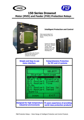
gGE Power ManagementMDPDigital Time Overcurrent RelayInstruction ManualMDP Revision: Rev. DManual P/N: GEK-100682DCopyright 2000 GE Power ManagementGE Power Management215 Anderson Avenue, Markham, OntarioCanada L6E 1B3Tel: (905) 294-6222 Fax: (905) 294-8512Internet: http://www.GEindustrial.com/pmManufactured under anISO9002 Registered system.
These instructions do not purport to cover all details or variations in equipmentnor provide for every possible contingency to be met in connection with installation, operation, or maintenance. Should further information be desired orshould particular problems arise which are not covered sufficiently for the purchaser’s purpose, the matter should be referred to the General ElectricCompany.To the extent required the products described herein meet applicable ANSI,IEEE, and NEMA standards; but no such assurance is given with respect tolocal codes and ordinances because they vary greatly.
TABLE OF CONTENTS1. INTRODUCTION1.11.21.31.41.51.6PRODUCT DESCRIPTION. 1-1ORDER CODES . 1-2APPLICATION . 1-4INTERFERENCE SUPPRESSION GROUND CONNECTION. 1-5TECHNICAL SPECIFICATIONS. 1-6RANGES AND SETTINGS . 1-72. OPERATINGPRINCIPLES2.12.22.32.42.52.92.10INPUTS. 2-1EXTERNAL INPUTS. 2-1COMMUNICATIONS PORT . 2-1MEASUREMENT . 2-3INVERSE TIME UNIT . 2-351 INVERSE (5 A RATED RELAYS). 2-4BS142 INVERSE (1 A RATED RELAYS) . 2-453 VERY INVERSE . 2-477 EXTREMELY INVERSE . 2-466 INVERSE LONG TIME . 2-4INSTANTANEOUS UNIT . 2-10CHANGING SETTINGS. 2-10SETTINGS . 2-11PICKUP TOC. 2-11PICKUP IOC . 2-11TIME DIAL . 2-11CURVE SELECTION. 2-11IOC DELAY. 2-12COMMUNICATIONS ADDRESS. 2-12OUTPUT CONTACT CONFIGURATION . 2-12DISPLAY AND RESET . 2-13SELF-TEST AND ERROR ROUTINES . 2-143. CONSTRUCTION3.13.23.3DESCRIPTION . 3-1DISPLAYS . 3-3RECEIVING, HANDLING, AND STORAGE . 3-34. INSTALLATION ANDMAINTENANCE4.14.2INSTALLATION . 4-1PERIODIC CHECKS AND ROUTINE MAINTENANCE. 4-55. PERIODIC &ACCEPTANCE TESTS5.15.25.3DESCRIPTION . 5-1VISUAL INSPECTION . 5-1INVERSE TIME UNIT . 5-1PHASE PICKUP CALIBRATION VERIFICATION . 5-1VERIFICATION OF OPERATING TIME. 5-2VERIFICATION OF TIME DIAL . 5-2INSTANTANEOUS UNIT . 5-3VERIFICATION OF PICKUP . 5-3VERIFICATION OF OPERATING TIME. 5-3GROUND UNIT. 5-3abcde2.62.72.8abcdefgabc5.4ab5.5GE Power ManagementMDP Digital Time Overcurrent Relayi
TABLE OF CONTENTS6. MDP-LINK defgh6.86.9OVERVIEW. 6-1SYSTEM REQUIREMENTS . 6-1HARDWARE. 6-1SOFTWARE . 6-1GENERAL OPERATION. 6-3MOUSE/KEYBOARD USAGE . 6-3MAIN HORIZONTAL MENU BAR. 6-3PULL-DOWN MENUS . 6-3DIALOG BOXES . 6-3LIST BOXES. 6-4ENTERING TEXT AND NUMBERS . 6-4MAIN MENU . 6-5MAIN MENU . 6-5RELAY FUNCTIONS . 6-5LOGIN. 6-5LOGOUT. 6-5HANG UP PHONE. 6-6REQUEST RELAY DATA . 6-6REQUEST FAULT DATA . 6-6RESET FAULT DATA . 6-6BREAKER STATUS . 6-7TRIP BREAKER . 6-7CLOSE BREAKER . 6-7LOCAL FUNCTIONS . 6-8SETUP . 6-8COMMUNICATION PORT NUMBER . 6-8DIAL TYPE . 6-8MODEM CONNECTION TIME . 6-8RELAY PARAMETERS . 6-9ADD RELAY TO LIST . 6-9DELETE RELAY FROM LIST . 6-9DISPLAY MODE . 6-10MEMORY AVAILABLE . 6-10HELP. 6-10EXITING MDP-LINK . 6-107. MODBUS PROTOCOL7.17.27.3A. MDP FAQA.1FREQUENTLY ASKED QUESTIONS . A-1B. CHANGE NOTESB.1B.2B.3REVISION HISTORY .B-1ADDITIONS TO MDP MANUAL .B-1CHANGES TO MDP MANUAL . B-2iiDESCRIPTION . 7-1OVERVIEW. 7-1MODBUS COMMANDS . 7-1aREAD HOLDING REGISTERS, FUNCTION CODE 03. 7-1bREAD INPUT REGISTERS, FUNCTION CODE 04 . 7-2cFORCE SINGLE COIL: FUNCTION CODE 05. 7-27.4MODBUS MEMORY MAP . 7-37.5COIL COMMANDS . 7-67.6EVENT HANDLING . 7-6MDP Digital Time Overcurrent RelayGE Power Management
GEK-100682D1 INTRODUCTION1 INTRODUCTION1.1 PRODUCT DESCRIPTIONThe MDP Digital Time Overcurrent Relay is a digital, microprocessor based, nondirectional overcurrent relaythat protects against phase-to-phase and phase-to-ground faults. The MDP performs the following functions: Inverse overcurrent, including four characteristic curves and four values of definite time protection, as wellas instantaneous overcurrent protection with programmable delay Phase and ground current measurement Phase and ground current metering Operating time and fault current of the last trip Breaker status Breaker operation (RS232 and RS485 versions only)The MDP series relays include four measuring units, one for each of the three phase currents and an additional one for ground or residual current. Each of the four measuring units includes a time and an instantaneous overcurrent unit. The phase settings are combined so that all phase units are set the same.Table 1–1: CURRENT RANGESNOMINALCURRENT (In)INVERSE TIME UNIT (Is)PHASEGROUNDINSTANTANEOUSUNIT1.5 to 13.125 A1.5 to 13.25 A0.5 to 4.375 A5A0.1 to 0.875 A0.5 to 4.375 A0.5 to 4.735 A0.3 to 2.625 A1A0.3 to 2.625 A1 to 31 Is(all relays)0.1 to 0.875 A0.05 to 0.4375 A(½ A CT)The pickup value for the instantaneous unit can be adjusted between 1 and 31 times the value selected for theinverse time unit.The instantaneous unit can be disabled by adjusting the setting to zero times the inverse value. The MDP relayhas two trip output relays that can be selected to indicate whether a trip has been produced by an instantaneous unit or an inverse unit, or by phase or ground.This selection is made by means of a switch behind the right lower side of the nameplate. An alarm output isprovided to signal a critical alarm (such as power supply failure or self check failure). An output contact is provided to close the breaker from a command issued via the communications channel.A single-line diagram illustrating the functionality of the MDP relay is shown on the following page. A typicalwiring diagram is shown in Figure 1–2: TYPICAL WIRING DIAGRAM on page 1–3.GE Power ManagementMDP Digital Time Overcurrent Relay1-11
1 INTRODUCTIONGEK-100682D1TRANSFORMER 150/51BUS 150/51FEEDERNO. 150/51FEEDERNO. 250/51FEEDERNO. 3707750A1.CDRFigure 1–1: SINGLE-LINE DIAGRAM1.2 ORDER CODESMDPSSSSS012345123456712300000D1-2No communications or control inputs(Block Ground, Block Instantaneous, Breaker Status)Control Inputs and communications upgrade socketCommNetModbus RTURS232RS4855 A nominal, 0.5 to 4.375 A ground, 1.5 to 13.125 A phase5 A nominal, 1.5 to 13.125 A ground, 1.5 to 13.125 A phase5 A nominal, 0.1 to 0.875 A ground, 1.5 to 13.125 A phase1 A nominal, 0.1 to 0.875 A ground, 0.3 to 2.625 A phase1 A nominal, 0.3 to 2.625 A ground, 0.3 to 2.625 A phase1 A nominal, 0.05 to 0.4375 A ground, 0.3 to 2.625 A phase5 A nominal, 0.5 to 4.375 A ground and phase24 to 48 V DC48 to 125 V DC, 35 to 120 V AC110 to 250 V DC, 85 to 240 V ACReservedRevision LevelMDP Digital Time Overcurrent RelayGE Power Management
GEK-100682D1 INTRODUCTION1ALTERNATIVE CT WIRINGFOR RESIDUAL GROUND SENSING11A231A 1B451B 1C671C 1G81GCURRENT INPUTSZERO SEQUENCE GROUNDSENSING CONNECTIONCIRCUIT BREAKERABCCONTROLPOWER52a52aTRIPCOIL10 2011A231A 1B451B 1C671C 1G81GPOWERSUPPLYCURRENT INPUTSSWITCHGEARGROUND BUST13T12GE Power Management111415161718SHIELDEDTWISTED PAIRCP4RS232CP6TX CP1CP7RX CP3CP8COMCP2CP5919707754A3.CDRFigure 1–2: TYPICAL WIRING DIAGRAMGE Power ManagementMDP Digital Time Overcurrent Relay1-3
1 INTRODUCTIONGEK-100682D1.3 APPLICATION1Time-overcurrent relays are used for the protection of feeders, transmission lines, alternating-current machinesand transformers, and numerous other applications where accurate measurement of current and timing is necessary. To ensure proper coordination with a minimum of circuit isolation, the operating time of associated protective devices should be considered when selecting a time-current characteristic for a particular application.Four basic time-current characteristics are available for the MDP relay:1. INVERSE / BS142 INVERSE: The inverse time current characteristic curves are shown in the followingdiagrams: Figure 2–4: INVERSE TIME CURVE on page 2–5. Figure 2–5: LONG INVERSE TIME CURVE on page 2–6. Figure 2–8: BS142 INVERSE TIME CURVE (1 A MODELS ONLY) on page 2–9.The BS142 inverse curve applies to the 1 A model relays only. These relays are generally applied wherethe short circuit current magnitude is dependent largely upon the system generating capacity at the time ofthe fault.2. VERY INVERSE: The very inverse time-current characteristic shown in Figure 2–6: VERY INVERSE TIMECURVE on page 2–7 is generally applied where the magnitude of short circuit current flowing through anygiven relay is more dependent upon the location of the fault relative to the relay than on the system generation setup at the time of the fault.3. EXTREMELY INVERSE: The extremely inverse time-current characteristic shown in Figure 2–7:EXTREMELY INVERSE TIME CURVE on page 2–8 is preferred for applications where sufficient timedelay must be provided to allow a re-energized circuit to pick up an accumulated cold load without unnecessary tripping on inrush currents. Distribution feeder circuits are a good example of such applications, andthe extremely-inverse characteristic is best suited to such applications because it more nearly approximates typical power fuse and fuse cutout characteristics.The general practice for grounded distribution system protection is to use three-phase overcurrent functions forprotection against interphase faults and a ground/residual overcurrent function for single phase-to-groundfaults. The use of a separate ground-overcurrent function is advantageous because it can generally beadjusted to provide faster and more sensitive protection for single phase-to-ground faults than the phase overcurrent functions. Typical connections for such an application are shown in Figure 4–2: TYPICAL EXTERNALCONNECTIONS, GROUND CURRENTS and Figure 4–3: TYPICAL EXTERNAL CONNECTIONS, RESIDUALCURRENTS on pages 4–2 and 4–3.The pickup setting of the MDP time unit should be chosen so that it operates for all short circuits in the protected zone and, when possible, also provides backup protection for short circuits in the immediately adjacentsystem element. The time unit pickup should be set low enough to ensure that the minimum fault current is atleast 1.5 times the setting.The time delay adjustment of the time unit should be chosen to assure selectivity with the protection on theadjacent system elements. This adjustment should be made for the condition that yields maximum fault currentat the relay location. The time delay is determined by the adjacent relay operating time for this condition, plus acoordinating time allowance that includes the adjacent circuit breaker maximum operating time and a safetyfactor to accommodate any uncertainties. Since the MDP time unit has insignificant overtravel, the only relayvariation that needs consideration in the safety factor is the tolerance on the time curves. A 0.17 second safetyfactor is generally used if the relay time is determined by selecting a time dial setting from the time curves. Thissafety factor can be reduced to 0.07 second if the time unit is instead set to the desired time by accurate tests.1-4MDP Digital Time Overcurrent RelayGE Power Management
GEK-100682D1 INTRODUCTIONThe instantaneous overcurrent unit can be applied in many instances to reduce the fault clearing time for highfault currents. This unit is normally set to pick up only on internal faults in the protected zone. Significant transient overreach can be experienced under certain conditions, and this must be taken into account by selectinga pickup setting that is higher than that which would be dictated by the maximum steady state external faultcurrent.NOTEIMPORTANT: If one unit (instantaneous or inverse) operates, the other unit (inverse or instantaneous) will also operate. The MDP fault report will record the first fault that occurred. Whenthe fault is cleared, the fault LEDs will display Phase-Phase, Phase-Ground, Instantaneous,and Inverse Time faults. See display section on how to interpret the display for various faultconditions. The MDP generates a new fault report when the fault current drops below the pickup value and a new fault occurs.Contact converter input CC1 and the output select switch of the MDP allow a zone selective interlocking of theMDP relays. This scheme provides instantaneous operation (with a minimum time delay) of the upstream relayfor faults between the upstream and downstream relays. Refer to Figure 4–4: TYPICAL EXTERNAL CONNECTIONS, ZONE SELECTIVE INTERLOCK on page 4–4 for a typical scheme and settings considerations.Note that all the feeders must be radial, with no (or very weak) source.1.4 INTERFERENCE SUPPRESSION GROUND CONNECTIONThe MDP relay contains high frequency interference protection consisting of a series of capacitors connectedbetween the input terminals and the case.The case stud of the relay should be connected to ground, so these interference suppression circuits can perform their protective function. This connection should be as short as possible, to assure maximum protection.Braided #12 AWG conductors are recommended.GE Power ManagementMDP Digital Time Overcurrent Relay1-51
1 INTRODUCTIONGEK-100682D1.5 TECHNICAL SPECIFICATIONS1ELECTRICAL RATINGSNominal frequency:25/50/60 HzNominal current:1 or 5 AAuxiliary Power Supply: 24 to 48 V DC, 48 to 125 V DC / 38.5 to 150 V AC, 110 to 250 V DC, 85 to 240 V ACBURDEN RATINGSGROUNDCTMDPMODEL1PHASEINPUT60.05 to 0.4375 A40.1 to 0.875 A50.3 to 2.625 A30.1 to 0.875 A1, 70.5 to 4.37521.5 to 13.125 A1A5A1.BURDEN50 Hz AC60 Hz AC0.09 Ω 2.4 0.09 Ω 2.8 0.01 Ω 9.7 0.01 Ω 11.5 POWER SUPPLYAC/DC 3 W at all voltages,quiescent 4.5 W at maximumvoltagesRefers to the MDP*X model, see Section 1.2: ORDER CODES on page 1–2OVERCURRENT RATINGSContinuous:Three Second:2 x In50 x InOne Second:100 x InCT RATINGS1A5A34500875001 A special13600 (models MDPx6 have a sensitive ground CT)ENVIRONMENTAL RATINGSTemperature:Operating:Storage:–20 C to 65 C (–40 C available upon request)–40 C to 65 CRelative Humidity:Up to 95% without condensingACCURACYOperating Value:5%Operating Time:5% or 0.025 seconds, whichever is greaterREPEATABILITYOperating Value:1%Operating Time:2% or 0.025 seconds, whichever is greaterDIGITAL INPUTVoltage Range:Frequency Range:38.5 to 250 V AC, 24 to 250 V DC40 to 70 HzOUTPUT AND TRIP CONTACTSClosing:Contact will close and conduct up to a maximum of 30 A for tripping duty at control voltages up to300 V DC. The output contact is also rated for Capacitive trip devices.Interrupting:Continuous:50 W resistive with a maximum of 2 A and 300 V DC5 A, with 300 V DC maximumFrequency range:25 to 70 Hz (note: the MDP responds to RMS values of harmonics to 600 Hz)1-6MDP Digital Time Overcurrent RelayGE Power Management
GEK-100682D1 INTRODUCTION1.6 RANGES AND SETTINGS1The following indicates the ranges of standard models.NOMINAL CURRENT5 A Phase Unit Models (models 1 to 3):Phase Unit:1.5 to 13.125 A in cumulative increments of 0.375, 0.750, 1.50, 3.0, and 6.0 AGround Unit model 1: 0.5 to 4.375 A in cumulative increments of 0.125, 0.250,0.50,1.0, and 2.0 AGround Unit model 2: 1.5 to 13.125 Amps in cumulative increments of 0.375, 0.750, 1.50, 3.0, and 6.0 AGround Unit model 3: 0.1 to 0.875 Amp in cumulative increments of 0.025, 0.050, 0.10, 0.2, and 0.4 A5 A Phase Unit Model (model 7):Phase Unit:0.5 to 4.375 A in cumulative increments of 0.125, 0.25, 0.50, 1.0, and 2.0 AGround Unit:0.5 to 4.375 A in cumulative increments of 0.125, 0.250, 0.50, 1.0, and 2.0 A1 A Phase Unit (models 4 to 6):Phase Unit:0.3 to 2.625 A in cumulative increments of 0.075, 0.150, 0.30, 0.60, and 1.20 AGround Unit model 4: 0.1 to 0.875 A in cumulative increments of 0.025, 0.050, 0.10, 0.2, and 0.4 AGround Unit model 5: 0.3 to 2.625 A in cumulative increments of 0.075, 0.150, 0.30, 0.6, and 1.2 AGround Unit model 6: 0.05 to 0.4375 A in cumulative increments of 0.0125, 0.0250,0.050,0.1, and 0.2 ATIME DELAY (TOC)Independent for phase and ground.Depends on the curve selected. Five Inverse Time curves are available (see Section 2.5: INVERSE TIME UNIT on page 2–3), as well as four definite times (maximum time 2, 4, 6, and 8 seconds), all in the same relay.INSTANTANEOUS UNIT PICKUPIndependent for phase and ground.1 to 31 times the pickup of the TOC setting.A setting of zero (0) disables instantaneous unit. (X) no multiples selected.INSTANTANEOUS UNIT TIME DELAYIndependent for phase and ground.0 to 1.55 seconds in 50 millisecond steps.PHASE OPERATING CURVES CURVE SELECTIONAvailable Curves:Inverse/BS142* (for 1 A models), Long Time Inverse, Very Inverse, Extremely Inverse, Four familiesof definite time characteristics with maximum values of 2, 4, 6, and 8 secondsBetween each family of curves, a specific curve can be selected between 0.5 and 10 in cumulative steps of 0.5, 1, 2, 2 and4 for 5 a relays. The 1 A model range is from 0.05 to 1.0 in cumulative steps of 0.05, 0.1, 0.2, 0.2, and 0.4.GROUND OPERATING CURVES CURVE SELECTIONAvailable Curves:Inverse/BS142* (for 1 A models), Long Time Inverse, Very Inverse, Extremely Inverse, Four familiesof definite time characteristics with maximum values of 2, 4, 6, and 8 secondsBetween each family of curves, a specific curve can be selected between 0.5 and 10 in cumulative steps of 0.5, 1, 2, 2, and4 for 5 amp relays. A 1 amp model's range is from 0.05 to 1.0 in cumulative steps of 0.05, 0.1, 0.2, 0.2, and 0.4.BS142 is the INVERSE curve of the 1 A model.NOTECOMMUNICATIONS ADDRESSRange:002 to 998.A setting of 000 indicates no communications and sets the default display to phase A Current.For RS232 and RS485 all relays will respond to address 001.NOTEAll values are adjusted with DIP switches located at the front of the relay, except the communicationsaddress, which is located on the rear of the cradle.NOTEGE Power ManagementMDP Digital Time Overcurrent Relay1-7
1 INTRODUCTIONGEK-100682D11-8MDP Digital Time Overcurrent RelayGE Power Management
GEK-100682D2 OPERATING PRINCIPLES2 OPERATING PRINCIPLES2.1 INPUTSThe secondary current from the protected line current transformers is connected to the relay and immediatelyreduced via the internal current transformers. The MDP CT secondaries are connected across input resistors,yielding a voltage proportional to the relay input current. This voltage is rectified and filtered before beingapplied to the multiplexer and analog-to-digital converter, which are internal to the microprocessor.2.2 EXTERNAL INPUTSThree external inputs (CP4, CP6, and CP7) are provided. CP4 – Block IOC Trip: when energized, blocks tripping by the ground units. CP6 – Block Ground Trip: blocks the phase and ground instantaneous trip elements when it is energized. CP7 – Breaker Status Input: when energized, indicates that the Breaker Status is "closed".Since diode bridges are provided on all inputs, they can all be actuated by either switched-to-positive orswitched-to-negative, depending on the polarity connected to the stud. These inputs can be energized byeither AC or DC.The Breaker Status and Block Ground inputs, CP7 and CP6 respectively, must be switched by thesame polarity, since they share a common ground (CP8).NOTE2.3 COMMUNICATIONS PORTThe MDP relay has a communications feature that permits easy installation of various communications interface modules. The procedure for installation/replacement of a communications upgrade card is providedbelow:1. To install or replace a communications upgrade card, begin by removing the relay from the case.2. Before continuing, connect an approved wrist grounding strap to ground. This discharges any static electricity in your body that could damage the electronics of the MDP relay. A wrist strap is provided with thecommunications card kit. The wrist strap must provide a "safe" high resistance to ground.3. Remove four screws attaching the nameplate settings board and the NOMEX insulation paper to the relaycradle (see the cover photograph). Note that there are four metal spacers between the nameplate and thesettings board. Be careful not to lose them or let them fall into the relay assembly. Carefully place the settings board on top of the cradle to expose the communication card SIMM socket located on the lowestboard (digital input/communications board).4. To expose the SIMM socket located on the lowest board, carefully push down on the board to disengagethe board spacers. Do not try to remove the board from the cradle5. This step is for replacement only – skip to step 6 if you are installing the card for the first time. If you arereplacing an existing SIMM card, the old one must be removed! Start by simultaneously pushing thecatches on either side of the SIMM board outwards while lifting the board to a 45 angle. This will releasethe board.GE Power ManagementMDP Digital Time Overcurrent Relay2-12
2 OPERATING PRINCIPLESGEK-100682D6. Remove the communications card from its protective packaging. Insert the card into the SIMM socket at a45 angle to the socket with the integrated circuits facing up. Push the card down until it snaps into thesocket and the latches on either side of the board catch above the new board2Without Communications Upgrade CardCommunications Upgrade Card InstalledFigure 2–1: DIGITAL INPUT/COMMUNICATIONS BOARD7. Reassemble the MDP relay by engaging the board spacers of the lowest board (digital input/communications board) into the processor board above it. Align the NOMEX shield on the solder side of the settingsboard. Take one screw and spacer at a time and push the screw through the nameplate, spacer, settingsboard and NOMEX. The NOMEX protects the ribbon cable from the leads on the settings board.Before DI/Comm Board is Raised Back into PositionWith DI/Comm Board in PositionFigure 2–2: COMMUNICATIONS CARD INSTALLED2-2MDP Digital Time Overcurrent RelayGE Power Management
GEK-100682D2 OPERATING PRINCIPLES8. Tighten the screw just enough to hold the assembly in place until all four screws are aligned. When all thescrews are aligned, tighten them with gentle pressure so that the board is mounted evenly.9. SET THE COMMUNICATIONS ADDRESS before restoring the cradle to the case.2Figure 2–3: REAR VIEW SHOWING COMMUNICATION ADDRESS SWITCHES2.4 MEASUREMENTA timer internal to the microprocessor generates an interrupt every millisecond. Phase and ground measurements are made at each of these interrupts. These measurements are grouped, separately for each phase andground, in groups of ten, and the average of the maximum value of these groups is taken.This average is converted to a multiple of pickup TOC, the format used by the relay. This value is displayed in5 second intervals.2.5 INVERSE TIME UNITThe multiple of pickup TOC measurement obtained is compared, independently for each phase and ground,with a value, the pickup setting, that corresponds to one times (1 ) pickup TOC. If the measurement exceedsthe fixed setting, a Pickup LED lights on the front of the relay.The minimum current necessary to operate the Inverse Time measuring elements is never less than the setvalue (Is), nor greater than 10% more than (110% of) the set value.1.0 I s I min 1.1 I sThe dropout to pickup ratio is not less than 95%, based on the actual operating value.The MDP relay incorporates five inverse time curves and four definite times. The curve within a family isselected by the time dial. The characteristic curves for the MDP relay correspond approximately as follows.GE Power ManagementMDP Digital Time Overcurrent Relay2-3
1-2 MDP Digital Time Overcurrent Relay GE Power Management1 INTRODUCTION GEK-100682D 1 Figure 1-1: SINGLE-LINE DIAGRAM 1.2 ORDER CODES MDP S S S S S 0 No communications or control inputs (Block Ground, Block Instantaneous, Breaker Status)
