Transcription
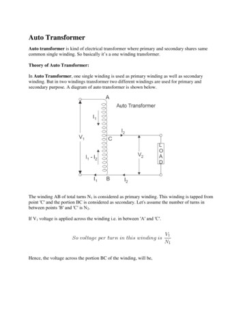
E-Series protective relaysFeeder distribution relaysMotor relaysTransformer relaysGenerator relaysE-Series protective relay familyReliable protection for every application
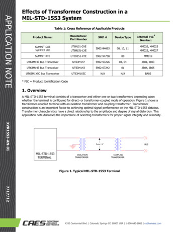
Eaton s E-Seriesrelay family introductionThe protective relay familyEaton’s E-Series microprocessor-based protective relays offer reliable, secure and complete protection andcontrol of power generation and distribution systems. The hardware and software commonality acrossthe E-Series family platform makes it easy for users to program simple to complex settings or schemesfor each of their unique applications. The powerful multi-core processors and intuitive user interfaceprovide for flexible configurations and simple alarming and notifications.Common features across the E-Series relay family include:Protection/security Maintenance mode Zone selective interlocking Multi-level password protected 00Control Programmable relay outputs Digital inputs with adjustable thresholds Eight common pushbuttons Programmable logic elements (up to 80) Wide AC/DC power supply rangeETR-5000EMR-3000Feeder distribution relayFeeder distribution relaysprovide complete protectionfor medium voltage feederdistribution lines.Models include: EDR-3000 EDR-5000Information Device setting and waveform software USB front access port High-contrast, illuminated HMI Programmable LEDs Cause-of-Trip indicationEGR-5000Motor relayTransformer relayGenerator relayMotor relays provide completeand reliable motor protectionfor any size motor at differentvoltage levels, includingdiagnostics, monitoring andstarting control functions.Models include: EMR-3000 EMR-4000 EMR-5000Transformer relays provideprimary protection, control andbackup protection of transformers,including current differential,restricted ground differentialand overcurrent protection.Models include: ETR-4000 ETR-5000Generator protection relayscan be used to protect any sizegenerators. They may be usedas primary or backup protectionin standby generators andcogeneration applications.Models include: EGR-5000Common software toolsAll E-Series relays use the same software interface for easy access to information and programming of settings.Whether you are using the front panel or the external software, the interface is the same on all rsDeviceParametersControlLogicDownload PowerPort-E software and device models including Quality Manager at www.eaton.com/pr2EATON E-Series protective relaysDevicePlanningService
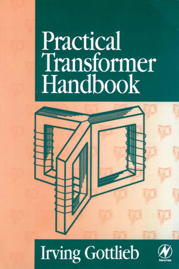
Common featuresCommunication and Connection InterfacesFront Panel Access(Removable Terminals)Rear ViewIRIG-B Time SyncRS-485 Connector (Standard)Fiber Optic Port—URTD ModuleEthernet (RJ-45) PortE-SeriesRS-232 Port (Standard)HMI and software displaythe same folder structureReference order guide for availability by model.E-Series relay family feature comparison ing and monitoring featuresCurrent (pos., neg. and zero seq.)Current unbalance % (I2/I1)Differential currentVoltage (L–L, L–N, pos., neg. and zero seq.)Voltage unbalance % (V2/V1)Phase anglesVolt-amps, watts, volt-amps reactivekWh (forward, reverse and net)kVArh (lead, lag and net)Power factorFrequencyVolts/Hz2nd harmonic current % (H2/fund.)3rd harmonic voltageTHD current (% and magnitude)THD voltage (% and magnitude)Minimum/maximum recordingSync valuesTemperature with remote URTD moduleTrip circuit monitoringBreaker wear and general countersCT supervisionVT supervisionWaveform recorder (7200 cycles total storage)Fault recorder (20 events)Sequence of events recorder (300 events)Trend recorderMotor history, start trending, thermal capacityGenerator hours of operationProgrammable logic equations (up to mmunications protocolsModbus RTU or DNP3 RTU over RS-485Modbus TCP or DNP3 TCP/UDP over Ethernet RJ-45PROFIBUS-DP over fiber optic STPROFIBUS-DP over D-Sub / RS-485Modbus RTU or DNP3 RTU over fiber optic STModbus RTU or DNP3 RTU over D-Sub / RS-485IEC 61850 or Modbus TCP or DNP3 TCP/UDPover Ethernet RJ-45Modbus RTU or DNP3 RTU over RS-485 orModbus TCP or DNP3 TCP/UDP over Ethernet RJ-45IEC 61850 or Modbus TCP or DNP3 TCP/UDPover LC duplex fiber optic EthernetModbus TCP or DNP3 TCP/UDP over LC duplexfiber optic EthernetEATON E-Series protective relays3
Eaton’s distribution relay family–EDR SeriesModel comparison guide–protective functionsEDR-3000EDR-5000Protection functions46—Current unbalance elements50BF—Breaker failure50P—Phase instantaneous overcurrent elements50R—Calculated ground or neutral instantaneous overcurrent elements50X—Measured ground or neutral instantaneous overcurrent elements51P—Phase overcurrent protection per time-current curve elements51R—Calculated ground fault protection per time-current curve elements51X—Measured ground or neutral fault protection per time-currentcurve elementsCLPU—Cold load pickupSOTF—Switch on to faultCTS—Current transformer supervision74TCM—Trip coil monitor (option)ZI—Zone selective interlocking (option)The EDR-5000 has all of the same protection functions as the EDR-3000 with additional features.Enhanced protection functions27A/M—Auxiliary and main three-phase undervoltage elements 51V—Voltage restraint elements47—Voltage unbalance elements79—Auto-reclosing55A/D—Apparent and displacement power factor elements27T—Low voltage ride-through (LVRT)59A/M—Auxiliary and main three-phase overvoltage elements 27Q—Reactive power and undervoltage59N—Ground fault overvoltage elements67P—Directional overcurrent elements67X—Calculated directional overcurrent elements78V—Vector surge element81U/O/R—Under and over and rate of change frequency elementsLOP—Loss of potential25—Sync check32—Forward and reverse watts elements32V—Forward and reverse VARs elementsTypical one-line example—ANSI protective elements guideProtective elements key1n Elements available onEDR-3000 and A4667P67Rn Elements availableon EDR-5000See Page 3 for 1R78V27M59M51V3232V1 52—circuit breaker.EDR family ordering guideEDR- 5000 -2 A 0 B A 1Relay modelMounting options3000 Current protection relay0 Standard mount1 Projection mount5000 Current, voltage and power protection relayEDR-3000 hardware option 1A 4 DI, 4 outputsB 8 DI, 6 outputs, trip coil monitorC 4 DI, 4 outputs, zone selective interlocking (ZSI)Conformal coating optionsORA NoneB Conformal coated circuit boardsand IRIG-BEDR-5000 hardware option 1A 8 DI, 10 outputs, ZSI and IRIG-BB 16 DI, 10 outputs, ZSI and IRIG-BHardware option 20 Phase current 5 A / 1 A, ground current 5 A / 1 A, power supply range: 19–300 Vdc, 40–250 Vac1 Phase current 5 A / 1 A, sensitive ground current 0.5 A / 0.1 A, power supply range: 19–300 Vdc,40–250 Vac4EATON E-Series protective relays Communication optionsB C D E F G H I Modbus/DNP3 RTU over RS-485Modbus/DNP3 TCP over Ethernet RJ-45PROFIBUS-DP over fiber optic STPROFIBUS-DP over D-Sub / RS-485Modbus RTU or DNP3 RTU over fiber optic STModbus/DNP3 RTU over D-Sub / RS-485IEC 61850/Modbus/DNP3 TCP over Ethernet RJ-45Modbus/DNP3 RTU over RS-485 or Modbus/DNP3TCP over Ethernet RJ-45K IEC 61850/Modbus/DNP3 TCP over LC duplexfiber optic EthernetL Modbus/DNP3 TCP over LC duplex fiber opticEthernet
Eaton’s motor relay family–EMR SeriesModel comparison guide–protective functionsEMR-3000EMR-4000EMR-5000Protection functions50BF—Breaker failure50P—Phase instantaneous overcurrent elements50R—Calculated ground or neutral instantaneous overcurrent elements50X—Measured ground or neutral instantaneous overcurrent elements51P—Phase overcurrent protection per time-current curve elements51R—Calculated ground fault protection per time-current curve elements51X—Measured ground or neutral fault protection per time-currentcurve elements46—Current unbalance elements49/38—Thermal protection using optional URTD module49/51—Thermal overload protection (I2T)49S/51—Locked rotor50J—Jam or stall protection37—Underload protection66—Starts per time period14—UnderspeedCTS—Current transformer supervision74TCM—Trip coil monitor (option)ZI—Zone selective interlocking (option)86—Lockout protectionThe EMR-4000 has all of the same protectionfunctions as the EMR-3000 with additional features.The EMR-5000 has all of the same protectionfunctions as the EMR-4000 with additional features.Enhanced protection functions27A/M—Auxiliary and main three-phaseundervoltage elements47—Voltage unbalance elements55A/D—Apparent and displacement powerfactor elements59A/M—Auxiliary and main three-phaseovervoltage elements59N—Ground fault overvoltage elements32/32V—Forward and reverse watts andVARs elements51V—Voltage restraint elements78V—Vector surge element81U/O/R—Under and over and rate of changefrequency elementsLOP—Loss of potentialCLPU—Cold load pickupSOTF—Switch on to faultBRB—Broken rotor bar detectionEnhanced protection functions87M—Differential current elementsTypical one-line example—ANSI protective elements guideProtective elements /5181U/O87M81R78V59Mn Elements availableon all EMR modelsn Elements available onEMR-4000 and EMR-5000n Elements availableon EMR-5000See Page 3 for S50X5150BF27A32V51V49/38URTD ModuleEMR family ordering guideEMR- 5000 -2 A 0 B A 1MountingoptionsRelay model3000 Current protection relayHardware option 24000 Current, voltage and power protection relay0 Phase current 5 A / 1 A,5000 Differential current, voltage and power protection relayEMR-3000 hardware option 1A 4 DI, 4 outputs, analog output, URTD interface, IRIG-BORand small displayB 4 DI, 4 outputs, zone interlocking (ZI), URTD interface IRIG-Band small displayEMR-4000 hardware option 1A 8 DI, 5 outputs, 4 analog outputs, ZSI URTD interface, IRIG-Band small displayEMR-5000 hardware option 1A 16 DI, 9 outputs, ZSI, URTD interface, IRIG-B and large displayB 8 DI, 9 outputs, 2 analog inputs, 2 analog outputs, ZSI, URTDORground current 5 A / 1 A,power supply range:19–300 Vdc, 40–250 Vac1 Phase current 5 A / 1 A,sensitive ground current0.5 A / 0.1 A, powersupply range: 9–300 Vdc,40–250 VacCommunication optionsB Modbus/DNP3 RTU over RS-485C Modbus/DNP3 TCP over EthernetRJ-45D PROFIBUS-DP over fiber optic STE PROFIBUS-DP over D-Sub / RS-485F Modbus RTU or DNP3 RTU overfiber optic STG Modbus/DNP3 RTU over D-Sub /RS-485H IEC 61850/Modbus/DNP3 TCP overEthernet RJ-45I Modbus/DNP3 RTU over RS-485 orModbus/DNP3 TCP over EthernetRJ-45K IEC 61850/Modbus/DNP3 TCP overLC duplex fiber optic EthernetL Modbus/DNP3 TCP over LC duplexfiber optic Ethernet0 Standardmount1 ProjectionmountConformal coatingoptionsA NoneB Conformalcoated circuitboardsinterface, IRIG-B and large displayEATON E-Series protective relays 5
Eaton’s transformer relay family–ETR SeriesModel comparison guide–protective functionsETR-4000ETR-5000Protection functions46—Current unbalance elements87R—Dual-slope percentage restrained current differential withmagnetizing inrush and over-excitation blocking87H—Unrestrained current differential87GD—Restricted ground fault / ground differential50P—Instantaneous overcurrent elements with timers50R—Instantaneous calculated elements with timers50X—Instantaneous measured elements with timers51P—Inverse time overcurrent elements51Q—Negative sequence phase overcurrent elements51R—Inverse time overcurrent calculated elements51X—Inverse time overcurrent measured elementsBF—Breaker failure elements49—Temperature protectionSOTF—Switch onto fault protectionCLPU—Cold load pickup74TCM—Trip coil monitorZI—Zone selective interlocking for bus protectionBF—Breaker failureThe ETR-5000 has all of the same protection functions as the ETR-4000 with additional features.Enhanced protection functions47—Voltage unbalance elements27M/59M—Main three-phase under/overvoltage protection27A/59A—Auxiliary single-phase under/overvoltage protection81—Frequency elements that can be assigned to: overfrequency,underfrequency, rate of change or vector surge32—Forward and reverse watts protection32V—Forward and reverse VARs protection24—Over-excitation, volts-per-hertz protection86—Lockout protection51V—Voltage restraint elements27T—Low voltage ride-through (LVRT)27Q—Reactive power and undervoltageLOP—Loss of potentialTypical one-line example—protection function guideWinding Side 111523Protective elements keyWinding Side 2n Functions on ETR-400052152CTRL52CTRLTCM8731TCMn Functions on ETR-4000and ETR-50003LOP87HSee Page 3 for 27MInrushBloc50PR8151PQR51PQR47464632/32V49CLPU SOTF87GD51V87GDH59A27A1 52—circuit breaker.ETR family ordering guideETR- 5000 -2 A 0 B A 1Relay model4000 Current and differential current protection relayCommunication options5000 Differential current, voltage and power protection relayETR-4000 hardware option 1A 8 DI, 9 outputs, removable terminals, 2 zoneORinterlocking (ZI) and URTD interfaceETR-5000 hardware option 1A 8 DI, 9 outputs, removable terminals, 2 zoneinterlocking (ZI) and URTD interfaceB 8 DI, 9 outputs, 2 AI, 2 AO, removable terminals,1 zone interlocking (ZI) and URTD interfaceHardware option 20 Phase current 5 A / 1 A, ground current 5 A / 1 A, power supply range:19–300 Vdc, 40–250 Vac1 Phase current 5 A / 1 A, sensitive ground current 0.5 A / 0.1 A, powersupply range: 19–300 Vdc, 40–250 Vac6EATON E-Series protective relays B C D E F G H I Modbus/DNP3 RTU over RS-485Modbus/DNP3 TCP over Ethernet RJ-45PROFIBUS-DP over fiber optic STPROFIBUS-DP over D-Sub / RS-485Modbus RTU or DNP3 RTU over fiber optic STModbus/DNP3 RTU over D-Sub / RS-485IEC 61850/Modbus/DNP3 TCP over Ethernet RJ-45Modbus/DNP3 RTU over RS-485 or Modbus/DNP3 TCPover Ethernet RJ-45K IEC 61850/Modbus/DNP3 TCP over LC duplexfiber optic EthernetL Modbus/DNP3 TCP over LC duplex fiber optic EthernetMountingoptions0 Standardmount1 ProjectionmountConformal coatingoptionsA NoneB Conformalcoated circuitboards
Eaton’s generator relay family–EGR SeriesModel comparison guide–protective functionsEGR-5000Protection functions50BF—Breaker failure50P—Phase instantaneous overcurrentelements50R—Calculated ground or neutralinstantaneous overcurrent elements50X—Measured ground or neutralinstantaneous overcurrent elements51P—Phase overcurrent protection pertime-current curve elements51V—Voltage restraint elements51R—Calculated ground fault protectionper time-current curve elements51X—Measured ground or neutralfault protection per time-currentcurve elements49/51—Thermal protection element67P/67R/67X—Directional overcurrent elements46—Current unbalance elements47—Voltage unbalance elements27A/27M—Auxiliary and main three-phaseundervoltage elements59A/59M—Auxiliary and main three-phaseovervoltage elements59N—Ground fault overvoltage element81U/O—Underfrequency andoverfrequency elements78V—Vector surge element55A/55D—Apparent and displacementpower factor elements32—Forward and reverse wattselements32V—Forward and reverse VARselements24—Over-excitation, volts-per-hertz27T—Low voltage ride-through (LVRT)27Q—Reactive power and undervoltage(64S) 27TN/59N—Stator ground fault46G—Generator unbalance40—Loss of excitation25—Sync check79—Auto-reclosing86—LockoutLOP—Loss of potentialCLPU—Cold load pickupSG Wear—Switchgear wearSOTF—Switch on to faultCTS—Current transformer supervision74TCM—Trip coil monitorZI—Zone selective interlocking87—Phase current differentialprotection87H—Unrestrained high-set differentialcurrent protection87GD—Restricted ground fault protection87GDH—High set restricted ground faultprotection50/27—Inadvertent energizationTypical one-line example—ANSI protective elements pictorial guideProtective functions keyn EGR-5000 Functions3See Page 3 for 1VSGWear55CTSLOPSOTF67R67P67X67N8750R51R11 52—circuit breaker.EGR family ordering guideEGR- 5000 -2 A 0 B A 1Relay modelMounting options5000 Differential current, voltage and power protection relayEGR-5000 hardware option 1A 16 DI, 9 outputs, ZSI and URTD interfaceB 8 DI, 9 outputs, 2 AI, 2 AO, ZSI and URTD interfaceHardware option 20 Phase current 5 A / 1 A, ground current 5 A / 1 A, power supply range:19–300 Vdc, 40–250 Vac1 Phase current 5 A / 1 A, sensitive ground current 0.5 A / 0.1 A, powersupply range: 19–300 Vdc, 40–250 VacCommunication optionsB C D E F G H Modbus/DNP3 RTU over RS-485Modbus/DNP3 TCP over Ethernet RJ-45PROFIBUS-DP over fiber optic STPROFIBUS-DP over D-Sub / RS-485Modbus RTU or DNP3 RTU over fiber optic STModbus/DNP3 RTU over D-Sub / RS-485IEC 61850/Modbus/DNP3 TCP over EthernetRJ-45I Modbus/DNP3 RTU over RS-485 or Modbus/DNP3 TCP over Ethernet RJ-45K IEC 61850/Modbus/DNP3 TCP over LC duplexfiber optic EthernetL Modbus/DNP3 TCP over LC duplex fiber opticEthernet0 Standard mount1 Projection mountConformal coating optionsA NoneB Conformal coated circuit boardsEATON E-Series protective relays 7
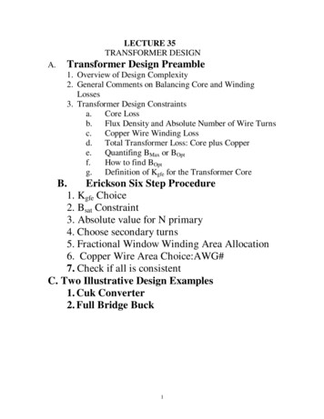
Common software toolsQuality Manager is a powerful waveform and events analysis software tool. Quality Manager allows the user to review andcustomize the waveform disturbance records downloaded from any of the E-Series family models.Features Zoom, scale and edit preferences for easyviewing and reporting 10 seconds maximum per record and 120seconds total data storage (customizable) Select and group desired measurementchannels for analysis Organize desired internal relay logic and I/Oon the same timeline as the measurementchannels for detailed sequence of eventsanalysis Easily monitor the sampled values of thewaveform recordDownload Quality Manager along with the PowerPort-E setting software at www.eaton.com/prE-Series relay family standard accessoriesDescriptionUniversal RTD module with Modbus RTU 48–240 Vac / 48–250 VdcUniversal RTD module with Modbus RTU 24–48 Vdc1 m fiber optic cable for EMR, ETR or EGR relays / URTD communications5 m fiber optic cable for EMR, ETR or EGR relays / URTD communications10 m fiber optic cable for EMR, ETR or EGR relays / URTD communications25 m fiber optic cable for EMR, ETR or EGR relays / URTD communications75 m fiber optic cable for EMR, ETR or EGR relays / URTD communicationsE-Series 3000 IQ adapter kit, projection mounted. For retrofitting MP and FP series relays to EMR-3000 and EDR-3000 relaysE-Series mini USB cable 6 ftEaton1000 Eaton BoulevardCleveland, OH 44122United StatesEaton.com 2016 EatonAll Rights ReservedPrinted in USAPublication No. BR026001EN / Z17866February 2016Eaton is a registered trademark.All other trademarks are propertyof their respective owners.Catalog MPFO-75ER-IQRETROKITESERIESUSBCBL
Eaton's motor relay family-EMR Series Model comparison guide-protective functions EMR-3000 EMR-4000 EMR-5000 Protection functions 50BF—Breaker failure 50P—Phase instantaneous overcurrent elements 50R—Calculated ground or neutral instantaneous overcurrent elements 50X—Measured ground or neutral instantaneous overcurrent elements 51P—Phase overcurrent protection per time-current .