Transcription
An Introduction to RP2040 PIO withCircuitPythonCreated by Jeff o-with-circuitpythonLast updated on 2022-03-24 06:43:51 PM EDT Adafruit IndustriesPage 1 of 25
Table of ContentsOverview3 Major differences between pio in CircuitPython compared to standard pioasm Products34Installing CircuitPython6 CircuitPython Quickstart Flash Resetting UF268Installing the Mu Editor8 Download and Install Mu Starting Up Mu Using Mu9910Installing Libraries10Using PIO to turn an LED on and off11 Code Walkthrough12Using PIO to control LED brightness14 Code Walkthrough15Using PIO to blink a LED quickly or slowly Code Walkthrough1617Using PIO to drive a NeoPixel19 Parts Full Code Listing Code Walk-through202122API Documentation: adafruit pioasm25API Documentation: rp2pio25 Adafruit IndustriesPage 2 of 25
OverviewA feature that sets the Raspberry Pi Foundation RP2040 microcontroller apart fromother microcontrollers is "PIO". The RP2040 datasheet says that the "programmableinput/output block (PIO) is a versatile hardware interface. It can support a variety of IOstandards PIO is programmable in the same sense as a processor."In this guide, you'll learn how to write and use PIO programs from CircuitPython. Theofficial datasheet (https://adafru.it/QLC) (chapter 3), the book "Get Started withMicroPython on Raspberry Pi Pico" (https://adafru.it/QLD) and pico-examples (https://adafru.it/Qa2) (pio folder) are helpful resources too, but CircuitPython sometimesdeviates from the way that PIO is used in other environments like C or MicroPython.Major differences between pio in CircuitPython comparedto standard pioasm.wrap and .wrap target are not supportedInstead, an implicit .wrap is at the bottom of every program, and an implicit.wrap target is at the top of every program. You can add a jmp instructioninstead of using .wrap but remember that this slightly changes the instructionlength and the timing of your pio program. Adafruit IndustriesPage 3 of 25
mov operator restrictionsThe mov instruction can accept an optional argument, called an operator, toreverse ( :: ) or invert ( ) its argument. In adafruit pioasm, one or more spacesmust come between the :: or and the operand. These spaces are not requiredby the official dialect.The official dialect allows "!" to mean the same as " ". This is not accepted byadafruit pioasm.Expressions are not supportedStandard pioasm supports expressions like [T1 1] . In pioasm, calculations arenot supported. Instead, use string formatting operations to insert the computedvalue where necessary, e.g., f""" [{T1 1}] """Interrupts are not supportedThe IRQ method of sending signals out of a PIO program is not supported inCircuitPython.ProductsThese examples were designed for the Raspberry Pi Pico but can be adapted to therange of boards with the RP2040 microcontroller. The QT Py RP2040 requires theaddition of an external LED and current-limiting resistor for the standard LEDexamples.Adafruit Feather RP2040A new chip means a new Feather, and theRaspberry Pi RP2040 is no exception.When we saw this chip we thought "thischip is going to be awesome when wegive it the Feather.https://www.adafruit.com/product/4884 Adafruit IndustriesPage 4 of 25
Adafruit ItsyBitsy RP2040A new chip means a new ItsyBitsy, andthe Raspberry Pi RP2040 is no exception.When we saw this chip we thought "thischip is going to be awesome when wegive it the fruit QT Py RP2040What a cutie pie! Or is it. a QT Py? Thisdiminutive dev board comes with one ofour new favorite chip, the RP2040. It'sbeen made famous in the newhttps://www.adafruit.com/product/4900Raspberry Pi Pico RP2040The Raspberry Pi foundation changedsingle-board computing when theyreleased the Raspberry Pi computer, nowthey're ready to.https://www.adafruit.com/product/4864Raspberry Pi Pico RP2040The Raspberry Pi foundation changedsingle-board computing when theyreleased the Raspberry Pi computer, nowthey're ready to.https://www.adafruit.com/product/4864 Adafruit IndustriesPage 5 of 25
Installing CircuitPythonCircuitPython (https://adafru.it/tB7) is a derivative of MicroPython (https://adafru.it/BeZ)designed to simplify experimentation and education on low-cost microcontrollers. Itmakes it easier than ever to get prototyping by requiring no upfront desktop softwaredownloads. Simply copy and edit files on the CIRCUITPY drive to iterate.CircuitPython QuickstartFollow this step-by-step to quickly get CircuitPython working on your board.Download the latest version ofCircuitPython for the Raspberry PiPico from circuitpython.orghttps://adafru.it/QaPClick the link above and download thelatest UF2 file.Download and save it to your desktop (orwherever is handy). Adafruit IndustriesPage 6 of 25
Start with your Pico unplugged from USB.Hold down the BOOTSEL button, andwhile continuing to hold it (don't let go!),plug the Pico into USB. Continue to holdthe BOOTSEL button until the RPI-RP2drive appears!If the drive does not appear, unplug yourPico and go through the above processagain.A lot of people end up using charge-onlyUSB cables and it is very frustrating! Somake sure you have a USB cable youknow is good for data sync.You will see a new disk drive appear calledRPI-RP2.Drag the adafruit circuitpython etc.uf2 fileto RPI-RP2. Adafruit IndustriesPage 7 of 25
The RPI-RP2 drive will disappear and anew disk drive called CIRCUITPY willappear.That's it, you're done! :)Flash Resetting UF2If your Pico ever gets into a really weird state and doesn't even show up as a diskdrive when installing CircuitPython, try installing this 'nuke' UF2 which will do a 'deepclean' on your Flash Memory. You will lose all the files on the board, but at least you'llbe able to revive it! After nuking, re-install CircuitPythonflash nuke.uf2https://adafru.it/QAJInstalling the Mu EditorMu is a simple code editor that works with the Adafruit CircuitPython boards. It'swritten in Python and works on Windows, MacOS, Linux and Raspberry Pi. The serialconsole is built right in so you get immediate feedback from your board's serialoutput!Mu is our recommended editor - please use it (unless you are an experiencedcoder with a favorite editor already!). Adafruit IndustriesPage 8 of 25
Download and Install MuDownload Mu from https://codewith.mu (https://adafru.it/Be6).Click the Download link for downloads andinstallation instructions.Click Start Here to find a wealth of otherinformation, including extensive tutorialsand and how-to's.Windows users: due to the nature of MSI installers, please remove old versions ofMu before installing the latest version.Starting Up MuThe first time you start Mu, you will beprompted to select your 'mode' - you canalways change your mind later. For nowplease select CircuitPython!The current mode is displayed in the lowerright corner of the window, next to the"gear" icon. If the mode says "Microbit" orsomething else, click the Mode button inthe upper left, and then choose"CircuitPython" in the dialog box thatappears. Adafruit IndustriesPage 9 of 25
Mu attempts to auto-detect your board onstartup, so if you do not have aCircuitPython board plugged in with aCIRCUITPY drive available, Mu will informyou where it will store any code you saveuntil you plug in a board.To avoid this warning, plug in a board andensure that the CIRCUITPY drive ismounted before starting Mu.Using MuYou can now explore Mu! The three main sections of the window are labeled below;the button bar, the text editor, and the serial console / REPL.Now you're ready to code! Let's keep going.Installing LibrariesYou'll need to install the Adafruit CircuitPython Pioasm library on yourCircuitPython board.First make sure you are running the latest version of Adafruit CircuitPython (https://adafru.it/Amd) for your board. Adafruit IndustriesPage 10 of 25
Next you'll need to install the necessary libraries to use the hardware--carefully followthe steps to find and install these libraries from Adafruit's CircuitPython library bundle(https://adafru.it/uap). Our CircuitPython starter guide has a great page on how toinstall the library bundle (https://adafru.it/ABU).Manually install the necessary library fromthe bundle:adafruit pioasm.mpyBefore continuing, make sure your board'slib folder or root filesystem has theadafruit pioasm.mpy file copied over.Using PIO to turn an LED on and offNormally, you'd use DigitalInOut to turn an LED on and off in CircuitPython.However, as a simple introduction to PIO, it can also be used to turn an LED on or off.Here's a CircuitPython program to do just that:# SPDX-FileCopyrightText: 2021 Jeff Epler, written for Adafruit Industries## SPDX-License-Identifier: MIT## Adapted from the example master/pio/hello pioimport timeimport boardimport rp2pio Adafruit IndustriesPage 11 of 25
import adafruit pioasmhello """.program helloloop:pullout pins, 1; This program uses a 'jmp' at the end to follow the example. However,; in a many cases (including this one!) there is no jmp needed at the end; and the default "wrap" behavior will automatically return to the "pull"; instruction at the beginning.jmp loop"""assembled adafruit pioasm.assemble(hello)sm rp2pio.StateMachine(assembled,frequency 2000,first out pin board.LED,)print("real frequency", sm.frequency)while bytes((0,)))time.sleep(0.5)Save the file below as code.py and transfer it to your CIRCUITPY drive. Your deviceshould automatically restart and run the code. Shortly, a LED will blink on and offabout once every second. If it doesn't, use Mu to connect to the Serial REPL (https://adafru.it/Awz) of your device and you'll be able to see any errors that occurred.Code WalkthroughThe full program is shown above, but let's look at the interesting bits a few lines at atime:hello """.program helloloop:pullout pins, 1; This program uses a 'jmp' at the end to follow the example. However,; in a many cases (including this one!) there is no jmp needed at the end; and the default "wrap" behavior will automatically return to the "pull"; instruction at the beginning.jmp loop"""PIO programs are included within your CircuitPython source as strings, and thenconverted into a program with the assemble function.sm rp2pio.StateMachine(assembled, Adafruit IndustriesPage 12 of 25
frequency 10000,first out pin board.LED,)The PIO peripheral contains several "state machines", which are the units that run PIOprograms. The StateMachine constructor takes the assembled program as well assome additional information: frequency says how quickly each pio instruction executes. If you have a taskthat you need to take "exactly X microseconds" or "execute at exactly Y kHz",this will allow you to determine the right frequency value. first out pin names the first pin that will be updated by out instructions inthe PIO program. This program only affects a single pin.while bytes((0,)))time.sleep(0.5)The forever-loop of our Python code alternates between sending the byte 1 and thebyte 0 to the PIO state machine. Each time a byte is sent, the PIO program acts on it.loop:pullout pins, 1jmp loopEvery PIO instruction is documented in the RP2040 datasheet, so while this guide willgive a high-level description of what is happening, it eliminates many details in orderto keep the descriptions sort.The first line, loop: , is a label. This line, together with the last line jmp loop createa forever-loop.The second line contains the first instruction, pull , which waits until a value is sentto the State Machine (A value is sent by the sm.write function calls in our Pythoncode). The value is stored in a location (register) called the OSR (Output Shift Register).The next line contains another instruction, out pins, 1 . This is our first instructionwith operands. The first operand, pins, says where the data is being transferred to.The second operand, 1, says how many bits are being transferred. The source of thedata is the OSR, the same as the implicit destination of the pull instruction. Adafruit IndustriesPage 13 of 25
The final line contains the last instruction, jmp loop . A jmp instruction makes theprogram continue at the named location instead of the next line.The net effect of this program is to turn the related pin HIGH if the number sent iseven and the pin LOW if the number sent is odd. And that's why the Python foreverloop makes the Pico's LED turn off and on about once per second.Using PIO to control LED brightnessNormally, you'd use PWMOut to control the brightness of an LED connected to a GPIOpin. However, as you may expect, you can also use PIO to create a PWM-like effect.Here's a CircuitPython program to do just that:# SPDX-FileCopyrightText: 2021 Jeff Epler, written for Adafruit Industries## SPDX-License-Identifier: MIT## Adapted from the an example in Appendix C of RPi PiPico Digital ruit pioasmled quarter brightness adafruit pioasm.assemble("""set pins, 0 [2]set pins, 1""")led half brightness adafruit pioasm.assemble("""set pins, 0set pins, 1""") Adafruit IndustriesPage 14 of 25
led full brightness adafruit pioasm.assemble("""set pins, 1""")while True:sm rp2pio.StateMachine(led quarter brightness, frequency 10000, first set pin board.LED)time.sleep(1)sm.deinit()sm rp2pio.StateMachine(led half brightness, frequency 10000, first set pin board.LED)time.sleep(1)sm.deinit()sm rp2pio.StateMachine(led full brightness, frequency 10000, first set pin board.LED)time.sleep(1)sm.deinit()Code WalkthroughThe full program is shown above, but let's look at the interesting bits a few lines at atime. In this example, there are three different PIO programs, each one for a differentbrightness level:led quarter brightness adafruit pioasm.assemble("""set pins, 0 [2]set pins, 1""")led half brightness adafruit pioasm.assemble("""set pins, 0set pins, 1""")led full brightness adafruit pioasm.assemble("""set pins, 1""")The "full brightness" program is most self-explanatory: at each moment, it sets itscorresponding pin to 1.The "half brightness" program alternately sets its pin to 0 and then to 1. When itchanges rapidly between these two states, the LED appears lit, but dim, to a humaneye. With a few exceptions, each instruction takes the same length of time. For oneinstruction the LED is off and for one instruction the LED is on, so the LED is turned onhalf the time. Adafruit IndustriesPage 15 of 25
The "quarter brightness" program needs the most explanation. The new element onthe first set line, [2] , indicates that after the set command, there is an additionaldelay of 2 cycles before going to the next instruction. That means that the pin is 0 for3 cycles and 1 for 1 cycle, giving a ratio of 1/4.while True:sm rp2pio.StateMachine(led quarter brightness,frequency 10000, first set pin board.LED)time.sleep(1)sm.deinit()sm rp2pio.StateMachine(led half brightness,frequency 10000, first set pin board.LED)time.sleep(1)sm.deinit()sm rp2pio.StateMachine(led full brightness,frequency 10000, first set pin board.LED)time.sleep(1)sm.deinit()The CircuitPython forever loop cycles among the three programs, for one secondeach. frequency 10000, or 10kHz, means that the on-off cycle of the LED is far toofast to be seen by a human eye; the quarter-brightness LED turns on and off 2500times per second, or 100 times faster than a "24fps" film.Because the LED is turned fully off for a short time between programs, you may see aflicker when the brightness changes.Using PIO to blink a LED quickly or slowlyThe next example program introduces new concepts: the pull instruction, whichreceives data from the CircuitPython program; and registers , which are similar tovariables in that they can store values and some simple operations can be performed Adafruit IndustriesPage 16 of 25
on those values. However, the uses of PIO registers are much more restricted thanthe use of variables in Python.# SPDX-FileCopyrightText: 2021 Jeff Epler, written for Adafruit Industries## SPDX-License-Identifier: MIT## Adapted from the example master/pio/pio p2pioadafruit pioasmblink adafruit pioasm.assemble(""".program blinkpull block; These two instructions take the blink durationout y, 32; and store it in yforever:mov x, yset pins, 1; Turn LED onlp1:jmp x-- lp1; Delay for (x 1) cycles, x is a 32 bit numbermov x, yset pins, 0; Turn LED offlp2:jmp x-- lp2; Delay for the same number of cycles againjmp forever; Blink forever!""")while True:for freq in [5, 8, 30]:with rp2pio.StateMachine(blink,frequency 125 000 000,first set pin board.LED,wait for txstall False,) as sm:data array.array("I", [sm.frequency // de Walkthroughpull block; These two instructions take the blink durationout y, 32; and store it in yThe instruction "pull block" says to wait until a value sent from CircuitPython isavailable ("block"), and then to pull that value into a holding area known as OSR , orOutput Shift Register. Then, all 32 bits of OSR are stored in the register called Y .Later, the CircuitPython program will send in a number that represents how long the Adafruit IndustriesPage 17 of 25
LED spends in an on or off state, so remember that this is what the register Y nowholds.forever:mov x, yset pins, 1lp1:jmp x-- lp1; Turn LED on; Delay for (x 1) cycles, x is a 32 bit numberThe next few lines' purpose is to turn the LED on, then wait for the desired length oftime.Working up from the bottom of this section of code, the last two lines create a loopthat delays for (x 1) cycles. lp1: is a label, and a jmp instruction can skip to itinstead of continuing to the next instruction. In this case, the jump is conditional onx-- , which means "if X is not zero, jump to lp1. In any case, decrease X by 1."Because the delay numbers are large and because the program will to change thedelay value without changing the PIO program itself, it cannot use the [#] notationto delay as in the previous program.The set instruction to turn on the LED should be familiar by now.The mov instruction takes the value in Y and copies it to X. If not, and the loop usedjmp y-- , then it would lose the original delay value. But the value is needed eachtime the program has a delay. Happily, there are two register X and Y so the programcan just take a copy of the original delay value each time.Remember that there's a forever: label here, it will be used later.mov x, yset pins, 0lp2:jmp x-- lp2jmp forever; Turn LED off; Delay for the same number of cycles again; Blink forever!The next block is very much like the previous block, except that set is used to turn theLED off before the delay.The final line, jmp forever , sends us back to the first delay. If it instead relied onthe automatic wrap back to the first instruction, there would only be a single on-offblink before the program went back to the pull block instruction and waited for a newblink duration to be sent in, which would not give the desired result.while True:for freq in [5, 8, 30]:with rp2pio.StateMachine( Adafruit IndustriesPage 18 of 25
blink,frequency 125 000 000,first set pin board.LED,wait for txstall False,) as sm:data array.array("I", [sm.frequency // e Python forever-loop repeatedly cycles through the frequencies 5, 8, and 30.For each frequency, it creates a state machine with our program, calculates and sendthe required delay value to it, and waits 3 seconds. Then, before continuing with thenext blink pattern, it delays a half a second.Of course, your CircuitPython program doesn't need to sleep while PIO is making theLED blink, it could be doing calculations, updating an LCD display, reading buttonpresses. The PIO program keeps running independently of what CircuitPython isdoing.In many applications of PIO, such as sending data out to NeoPixels, a write callneeds to wait until the PIO program has completed. Since PIO programs runendlessly, there needs to be some definition of "completed". The usual definition is"the PIO program (through a pull instruction) requested fresh data from CircuitPython,but none was available". This is called a "transmit stall" or "txstall". Thus, the line waitfor txstall False means that CircuitPython does not wait for this conditionbefore the sm.write(data) returns.Using PIO to drive a NeoPixel Adafruit IndustriesPage 19 of 25
If you are using a board with a built-in NeoPixel, the example on this page will use it. Ifyou have another board, such as a Raspberry Pi Pico, you'll need to connect it to anexternal NeoPixel:Connect Pico VSYS to NeoPixel or VCCConnect Pico GND to NeoPixel GNDConnect Pico GP16 to NeoPixel In or DINYou can also select whatever pin you likeand change the CircuitPython codeaccordingly.You can use any NeoPixel (including aNeoPixel strip) but this code example onlydrives a single NeoPixel at a time.PartsIf you have the Raspberry Pi Pico or another RP2040 board which does not have abuilt-in NeoPixel, you'll need the parts below to follow this example. Adafruit'sRP2040-based boards include a built-in NeoPixel.Breadboard-friendly RGB Smart NeoPixel Pack of 4This is the easiest way possible to addsmall, bright RGB pixels to your project.We took the same technology from ourFlora NeoPixels and made thembreadboard friendly, with two rows.https://www.adafruit.com/product/1312 Adafruit IndustriesPage 20 of 25
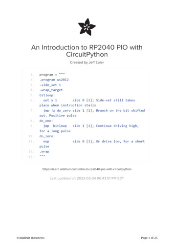
Half-Size Breadboard with MountingHolesThis cute 3.2″ 2.1″ (82 53mm)solderless half-size breadboard has fourbus lines and 30 rows of pins, our favoritesize of solderless breadboard ding wire bundle75 flexible stranded core wires with stiffends molded on in red, orange, yellow,green, blue, brown, black and white.These are a major improvement over the"box of bent.https://www.adafruit.com/product/153Full Code Listing# SPDX-FileCopyrightText: 2021 Scott Shawcroft, written for Adafruit Industries## SPDX-License-Identifier: crocontrolleradafruit pioasm# NeoPixels are 800khz bit streams. Zeroes are 1/3 duty cycle ( 416ns) and ones# are 2/3 duty cycle ( 833ns).program """.program ws2812.side set 1.wrap targetbitloop:out x 1side 0 [1]; Side-set still takes place when instruction stallsjmp !x do zero side 1 [1]; Branch on the bit we shifted out. Positive pulsedo one:jmp bitloopside 1 [1]; Continue driving high, for a long pulsedo zero:nopside 0 [1]; Or drive low, for a short pulse.wrap"""assembled adafruit pioasm.assemble(program)# If the board has a designated neopixel, then use it. Otherwise use Adafruit IndustriesPage 21 of 25
# GPIO16 as an arbitrary choice.if hasattr(board, "NEOPIXEL"):NEOPIXEL board.NEOPIXELelse:NEOPIXEL microcontroller.pin.GPIO16sm rp2pio.StateMachine(assembled,frequency 800000 * 6, # 800khz * 6 clocks per bitfirst sideset pin NEOPIXEL,auto pull True,out shift right False,pull threshold 8,)print("real frequency", sm.frequency)for i in "\x00\x00\x0a")time.sleep(0.1)print("writes done")time.sleep(2)Code Walk-throughExactly how does a NeoPixel expect toreceive data? Here's how. Each original bitneeds to be sent in approximately 1200microseconds. In the transmissionprogram, 1200 microseconds are dividedinto three equal portions.To transmit a "0", the pin is set HIGHduring the first third, and then LOW duringthe other two thirds.To transmit a "1", the pin is set HIGH duringthe first two thirds and low during the lastthird.This is repeated 24 times for each RGB NeoPixel, and a strip repeats these 24 cyclesonce for each pixel—once a pixel has received its own data, it sends any more data tothe next pixel using its Data Out (DOUT) pin.A short delay without any pulses makes the pixels ready to receive fresh values.program """.program ws2812 Adafruit IndustriesPage 22 of 25
.side set 1.wrap targetbitloop:out x 1jmp !x do zerodo one:jmp bitloopdo zero:nop.wrap"""side 0 [1]; Side-set still takes place when instruction stallsside 1 [1]; Branch on the bit shifted out. Positive pulseside 1 [1]; Continue driving high, for a long pulseside 0 [1]; Or drive low, for a short pulseThe first new concept is "side set". So far, PIO has changed a pin value using "out";with "side set" PIO can change the value of a pin while also doing some other activity.This is from the English idiom "do something on the side", which means in addition toone's regular job or duties.When an instruction has side 0 next to it, the corresponding output is set LOW, andwhen it has side 1 next to it, the corresponding output is set HIGH. There can be upto 5 side-set pins, in which case side N is interpreted as a binary number.The first instruction, out x 1 , transfers the next NeoPixel data bit into the x register.It also ensures the data out pin is LOW until the data bit is available. This creates thedelay necessary between refreshes of the NeoPixel strip, as well as the LOW periodat the end of each transmitted bit.Because the state machine is created with auto pull True , there's no need for a pull instruction.Next, jmp !x do zero side 1 sets the output pin HIGH and then continues eitherat the next line (if X is nonzero) or at do zero (if it is zero). !x means "if X is zero"and is taken from the syntax of C/C /Arduino code.Depending whether execution continues at do one or do zero , the middle portionof the signal is transmitted as HIGH or LOW. nop indicates that "no operation"(except the side-set operation) is performed by the instruction.Either way, PIO continues from bitloop: , setting the output pin LOW and thengetting the next pixel data into X. If there's more pixel data waiting to be transmitted,it will continue immediately on to the next lines; otherwise, it will wait until more pixeldata is available.If you consider each possible path through a single loop (X is zero; X is nonzero) andcount the number of instructions plus the number of [N] delays, you will see that thereare 6 clocks before the execution returns to bitloop . Adafruit IndustriesPage 23 of 25
sm rp2pio.StateMachine(assembled,frequency 800000 * 6, # 800khz * 6 clocks per bitfirst sideset pin NEOPIXEL,auto pull True,out shift right False,pull threshold 8,)print("real frequency", sm.frequency)Accordingly, the StateMachine is constructed with a requested frequency based onthe desired bit rate (800kHz) times the number of cycles per bit (6).As discussed above, since the out x instruction should wait until data is availableand then automatically pull it in from CircuitPython, auto pull True is specified.out shift right controls how multi-bit values are sent in. NeoPixels expect the"most significant bits" first, which is the order you get whenout shift right False .first sideset pin controls the pin(s) which are set by side-set operations.pull threshold controls the minimum number of bits that have to be available foran auto-pull to complete. Since neopixels are a sequence of bytes, set the value to 8,the number of bits in a byte.PIO can't exactly provide any requested frequency. In this case, instead of the exactvalue 4800000Hz a slightly different value of 4799760Hz is provided. This is wellwithin the tolerance of NeoPixels. When a device has to be controlled at a veryspecific frequency, it's important to check that your program is running at a rate that isclose enough to the required rate.for i in "\x00\x00\x0a")time.sleep(0.1)It's finally time to light up your NeoPixel by directly specifying the bytes to send to it.For most RGB NeoPixels, this program will send a sequence of green, red, and bluepixels, with 30 repetitions.On the RP2040, the standard neopixel module works very much in the way shownhere, but it's ready to work with the other CircuitPython libraries you may alreadyknow and love, like the LED animations library (https://adafru.it/LZF). Adafruit IndustriesPage 24 of 25
For a more sophisticated example of driving 8 NeoPixel strips from just 3 GPIO pinsusing PIO, there's a dedicated guide (https://adafru.it/QMd).API Documentation: adafruit pioasmAPI Documentation: adafruit pioasm (https://adafru.it/QMe)API Documentation: rp2pioAPI Documentation: rp2pio (https://adafru.it/QMf) Adafruit IndustriesPage 25 of 25
Nov 16, 2021 · The forever-loop of our Python code alternates between sending the byte 1 and the byte 0 to the PIO state machine. Each time a byte is sent, the PIO program acts on it. loop: pull out pins