Transcription
SPAJ 140 COvercurrent and earth-fault relayUser s manual and Technical description3I I2I n 1A 5AI n 1A 5Af n 50Hz60Hz(I )(I o )I5L1IL2IL3I 0 IRFSPAJ 140 C80.265V – 18.80V –I /I nU auxRESETSTEPt [s]kSPCJ 4D29I / I nREGISTERS0123456789000/I nI L2 / I nI L3 / I nIL1I max (15min) /I nt (I )[ % ]t (I )[ % ]I o /I nt (I o )[ % ]t (I o )[ % ]OPER.IND.t [s]0123456789I 0 / I nI STARTt 0 [s ]I TRIPk0I STARTI TRIPI o /I nI o STARTI o TRIPt o [s]PROGRAMSGFI o STARTI o TRIPSGBCBFPSGRRS 611 006 -Ser.No.0012A0074ATRIPSPCJ 4D29
SPAJ 140 CCombined overcurrentand earth-fault relay1MRS 750629Issued 1997-01-30Modified 2007-02-26Version DData subject to change without noticeContentsFeatures . 2Application . 2Description of operation . 3Connections (modified 2003-09) . 4Signal diagram . 7Signal abbreviations . 7Start and operation indicators . 8Power supply and output relay module . 9Technical data (modified 2007-02) . 10Maintenance and repairs . 13Spare parts . 13Dimensions and instructions for mounting . 14Order information . 14The complete manual for the relay SPAJ 140 C contains the following submanuals:General relay description for SPAJ 140 CGeneral characteristics of D type relay modulesCombined overcurrent and earth-fault relay moduletype SPCJ 4D29FeaturesThree-phase, low-set phase overcurrent unitwith definite time or inverse definite minimumtime (IDMT) characteristicThree-phase, high-set phase overcurrent unitwith instantaneous or definite time functionLow-set, non-directional earth-fault unit withdefinite time or inverse definite minimum time(IDMT) characteristicHigh-set, non-directional earth-fault unit withinstantaneous or definite time functionBuilt-in breaker failure protection functionTwo heavy-duty and four light-duty outputrelays with field-selectable configurationApplication2The combined overcurrent and earth-fault relaySPAJ 140 C is intended to be used for theselective short-circuit and earth-fault protectionof radial feeders in solidly earthed, resistanceearthed or impedance earthed power systems.The integrated protection relay includes a phaseovercurrent unit and an earth-fault unit with1MRS 7506291MRS 750066-MUM EN1MRS 750119Extensive data communication capabilities overbuilt-in serial portOutstanding design flexibility for easy selectionof appropriate operation schemes for differentapplicationsNumerical display of setting values, measuredvalues, memorized fault values, fault codes etc.Enhanced system reliability and availability dueto continuous hardware and software self-supervision with auto-diagnosisPowerful software support for setting andparametrizing of the relay and for recording ofrelay parameters with a portable PC.flexible tripping and signalling facilities. Theovercurrent and earth-fault relays can also beused inother applications requiring single-, twoor three-phase overcurrent protection and nondirectional earth-fault protection. The combined overcurrent and earth-fault relay also features circuit breaker failure protection.
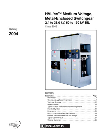
Description ofoperationThe combined overcurrent and earth-fault relayis a secondary relay to be connected to thecurrent transformers of the protected object.The three-phase overcurrent unit and the earthfault unit continuously measure the phase currents and the neutral current of the protectedobject. On detection of a fault the relay starts,trips the circuit breaker, initiates auto-reclosing,provides alarm, records fault data etc. in accordance with the application and the configuredrelay functions.When the phase current exceeds the set startcurrent of the low-set stage I , the overcurrentunit starts delivering a start signal after a preset 60 ms start time. When the set operate time atdefinite time operation or the calculated operatetime at inverse time operation elapses, the overcurrent unit operates. In the same way the highset stage I of the overcurrent unit starts delivering a start signal after a preset 40 ms starttime, when the set start current is exceeded.When the set operate time elapses, the overcurrent unit operates.When the earth-fault current exceeds the setstart current of the low-set stage I0 , the earthfault unit starts delivering a start signal after apreset 60 ms start time. When the set operatetime at definite time operation or the calculatedoperate time at inverse time operation elapses,the earth-fault unit operates. In the same waythe high-set stage I0 of the earth-fault unitIL1starts delivering a start signal after a preset 40ms start time, when the set start current isexceeded. When the set operate time elapses, theearth-fault unit operates.The low-set stage of the overcurrent unit and thelow-set stage of the earth-fault unit may be givendefinite time or inverse definite minimum time(IDMT) characteristic. When the IDMT characteristic is chosen six time/current curves areavailable. Four of the curves comply with the BS142 and IEC 60255 and are named "Normalinverse", "Very inverse", "Extremely inverse"and "Long-time inverse". The two additionalinverse time curves called the "RI-curve" andthe "RXIDG-curve" are also provided.By appropriate configuration of the output relaymatrix, the start signals of the overcurrent andearth-fault units are obtained as contact functions. The start signals can be used for blockingco-operating protection relays, for signallingand for initiating auto-reclosing.The relay includes one external binary input,which is controlled by an external control voltage. The function of the control input is determined by selector switches in the protectionrelay module. The control input can be used forblocking the operation of one or more protection stages, for resetting a latched output relay inthe manual reset mode or for enforcing a new setof relay setting parameters by remote control.TRIPTHREE PHASE DEFINITE TIMEOR INVERSE TIME LOW-SETOVERCURRENT PROTECTION51THREE PHASE INSTANTANEOUSOR DEFINITE TIME HIGH-SETOVERCURRENT PROTECTION50DEFINITE TIME OR INVERSE TIMELOW-SET EARTH-FAULTPROTECTION51 NINSTANTANEOUS OR DEFINITETIME HIGH-SET EARTH-FAULTPROTECTION50 NSIGNAL 1IL2IL3IoBLOCKINGREMOTE RESET, REMOTE SETTINGCONTROL OR BLOCKING INPUT FORTHE DIFFERENT CURRENT STAGESCIRCUIT BREAKER FAILUREPROTECTIONSIGNAL 2START 1START 251BFIRFOR RESETSERIAL I/OSERIAL COMMUNICATION PORTFig. 1. Protection functions of the combined overcurrent and earth-fault relay type SPAJ 140 C.3
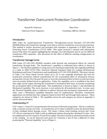
5A1A5A1A10L1L2L3I0-0I-TRIP SIGNAL 2 SIGNAL 1 START 2U auxSGR3/1SGB/6SGB/71 SGR1/2SGR1/4SGR1/6SGR1/8 ( )START 165 66SGR2/8- ( )68 69SGR2/6IRF80 81 LATCHING77 78 SGR2/4ASGR2/2B174 75 2/3TS21SGR1/5SS3SGR1/3SS2SGR3/662 61 70 71 72 SGR3/8SS1SGR1/111 SGR3/3EXTERNALCONTROLFSGR3/7TS11T9SGR3/4 -IRFI/OSGR3/27 8 9 25 26 275A1A1 23 4 5 6U2U13I 3I Io Io RC B/8SPA-ZCRRxTxTRIPSERIALPORTT2T4T6T8U145A1ASPAJ 140 CConnections(modified 2003-09)Fig. 2. Connection diagram for the combined overcurrent and earth-fault relay type SPAJ 140 C.
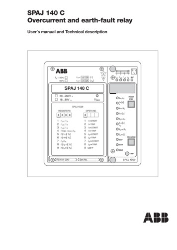
SPAAuxiliary voltageOutput relaysSelf-supervisionSwitchgroups for the configuration of the output relaysSwitchgroup for the configuration of the blocking or control signalTrip output relaySignal on operation of the overcurrent unitSignal on operation of the earth-fault unitStarting or auxiliary trip signal as selected with switchgroup SGR3Start signal of the low-set overcurrent stage I Overcurrent and earth-fault relay module SPCJ 4D29Input module SPTE 4E1Power supply and output relay module SPTU 240 R1 or SPTU 48 R1Start and operation indicationsSerial communication portBus connection moduleReceiver bus terminal (Rx) and transmitter bus terminal (Tx) of the busconnection moduleSerial PortUauxA, B, C, D, E, FIRFSGRSGBTRIPSIGNAL 1SIGNAL 2START 1START 2U1U3U2T1 T9SERIAL 80Made in Finland8125 7226 1027 11Fig. 3. Terminal arrangement of the overcurrent and earth-fault relay type SPAJ 140 C.5
The energizing currents of the overcurrent unitare connected to terminals 1-2, 4-5 and 7-8,when the rated current of the CT secondarycircuits is In 5 A. When the rated current of theCT secondary circuits is In 1 A, terminals 1-3,4-6 and 7-9 are used. The relay can also be usedin single-phase or two-phase applications simply by leaving one or two energizing inputsunoccupied. In single-phase applications thesame energizing current can be routed throughtwo energizing inputs, which may increase theoperating speed of the overcurrent unit, especially at instantaneous operation.The energizing current for the earth-fault unit isconnected to terminals 25-26 when the ratedcurrent In 5 A and to terminals 25-27 whenthe rated current In 1 A.The control input 10-11 can be used in threedifferent ways, i) as control input for an externalblocking signal, ii) as the control input forunlatching the trip relay, or iii) as the controlinput for the remote control of relay settings.The requested function is selected by means ofswitches switchgroup SGB in the main menu ofthe protection relay module.The auxiliary supply voltage of the relay isconnected to terminals 61-62. At d.c. supplythe positive lead is connected to terminal 61.The level of the voltage to be applied to theterminals depends on the type of power supplyand output relay module inserted in the relay.For further details see the description of thepower supply module. The permitted auxiliaryvoltage range of the relay is marked on the relayfront panel.Output relay A is a heavy-duty trip relay capableof controlling most circuit breakers. The operate signals of the different protection stages arerouted to the trip relay with switches 2,4,6 and8 of switchgroup SGR1. On delivery from thefactory all the protection stages are routed to thetrip relay. A latching of the output relay A canbe selected with switches 6 and 7 of switchgroupSGB.Output relays B and C can be used for signallingon operation of the relay module. The signals tobe routed to the output relays B and C are6selected with switches1.8 of switchgroup SGR2.The switch matrixes for routing operate signalsto the output relays B and C are identical.Normally output relay B is used for signalling onoperation of the overcurrent unit and C forsignalling on operation of the earth-fault unit.This is also the default setting of the relay ondelivery from the factory.The start signals of the protection stages of therelay are routed to output relay D. The signals tobe routed to output relay D are selected bymeans of switches 1, 3, 5 and 7 of switchgroupSGR1, which is a software switchgroup found inthe main menu of the protection relay module.The start signals of the low-set and high-set stageof the overcurrent unit are selected with switches1 and 3, and the start signals of the high-set andlow-set stage of the earth-fault unit with switches5 and 7.The output relay E is a heavy-duty relay asoutput relay A. It can be controlled by the startand operate signals of the protection stages.Output relay E is also used a trip relay for thecircuit breaker failure protection (CBFP), whenthe CBFP protection is used. In this case the tripsignal can be used either to control a circuitbreaker upstreams or to control a second tripcoil on the main circuit breaker to increase theredundancy of the circuit breaker.Output relay F functions as output relay for theself-supervision system of the protection relay.The F relay is energized under normal operatingconditions and contact gap 70-72 is closed. If afault is detected by the self-supervision system,or on loss of auxiliary supply, the output relaydrops off and the NO contact 71-72 closes.By means of bus connection modules typeSPA -ZC17 and SPA-ZC21 the relay connectsto the fibre-optic SPA bus via a 9-pole, D-typesubminiature connector located at the rear panelof the relay. The terminals of the fibre-opticcables are connected to the counter terminals Rx(receiver) and Tx (transmitter) of the bus connection module. The fibre-optic cables are linkedfrom one relay to another and to the substationlevel communication unit, for instance typeSRIO 1000M.
Signal diagramThe figure below schematically illustrates howthe start, trip, control and blocking signals canIL1I t , kIL2be configured to obtain the required protectionfunctions.SGR3 / 1SGR1 / 1SGR3 / 2SGR2 / 1SGR2 / 2SGR1 / 2IRFSGR3 / 3IL3SGB / 1I t SGR1 / 3SGF2 / 7SGR3 / 4SGR2 / 3SGR2 / 4SGR1 / 4SGB / 6TS11RESET PROGRAMSS1SGF2 / 8IoSGB / 3Io to DSIGNAL 1CSIGNAL 2BTRIPA(AR3)SGR3 / 5SGR1 / 5SGR3 / 6SGR2 / 5SGR2 / 6SGR1 / 6SGR3 / 7SGR1 / 7SGR3 / 8SGR2 / 7SGR2 / 8SGR1 / 8START 20.1.1sSS2to , koE(AR2)SGF1 / 41Io START 1F1SGB / 2BSIRFSS3(AR1)SGB / 7RESET PROGRAMTS211TRIPRESETSGB / 4SGB / 5SGB / 8REMOTE SETTINGSRELAY RESETREDUCED BLOCK DIAGRAMSPCJ 4D29SPTU R1Fig. 4. Signal diagram of the combined overcurrent and earth-fault relay type SPAJ 140 CThe functions of the blocking and start signalsare selected with the switches of switchgroupsSGF, SGB and SGR. The checksums of theswitchgroups, are found in the setting menu ofSignalabbreviationsIL1, IL2, IL3I0BSSS1SS2SS3TS1TS2BSAR1.3IRFSGFSGBSGRthe protection relay module. The functions ofthe different switches are explained in detail inthe user s manual of the protection relay module SPCJ 4D29.Energizing current of phase L1, L2 and L3Neutral current (Residual current)Blocking or control signalStart signal 1Start signal 2Start signal 3Operate signal 1 (Trip signal 1)Operate signal 2 (Trip signal 2)Blocking signalAuto-reclose start signals (not in use in relay SPAJ 140 C)Internal relay failureSwitchgroup for functionsSwitchgroup for blockingsSwitchgroup for relay configuration7
Operationindicators3I I2(I )I n 1A 5A (I o )I n 1A 5Af n 50Hz60HzI5L1IL2IL3I 0 IRFSPAJ 140 C80.265V – 18.80V –I /I nU auxRESETSTEPt [s]kSPCJ 4D29REGISTERS00 0123456789/I n/I nI L3 / I nIL1IL2I max (15min) /I nI o /I nt (I o )[ % ]t (I o )[ % ]t [s]00t (I )[ % ]t (I )[ % ]I / I nOPER.IND.123456789I 0 / I nI STARTt 0 [s ]I TRIPk0I STARTI TRIPt o [s]PROGRAMI o TRIPSGFI o STARTI o TRIPCBFPSGB0012A0074ATRIPSer.No.B) If the display is dark when one of the protection stages I , I , I0 or I0 operates, thefaulty phase or the neutral circuit is indicatedwith a yellow LED. If, for instance, the TRIPindicator glows red, and the indicators IL1and IL2 at the same time are lit, overcurrenthas occurred on phase L1 and L2.I o /I nI o STARTSGRRS 611 006 -A) The indicator TRIP is lit when one of theprotection stages operates. When the protection stage resets, the red indicator remains lit.SPCJ 4D29C) Besides being a code number at data presentation, the leftmost red digit in the displayserves as a visual operation indicator. Anoperation indicator is recognized by the factthat the red digit alone is switched on. Thefollowing table named OPERATION IND.on the relay front panel is a key to thefunction code numbers used.Indication Explanation123456789I STARTI TRIPI STARTI TRIPI0 STARTI0 TRIPI0 STARTI0 TRIPCBFP The low-set stage I of the overcurrent unit has started The low-set stage I of the overcurrent unit has operated The high-set stage I of the overcurrent unit has started The high-set stage I of the overcurrent unit has operated The low-set stage I0 of the earth-fault unit has started The low-set stage I0 of the earth-fault unit has operated The high-set stage I0 of the earth-fault unit has started The high-set stage I0 of the earth-fault unit has operated Circuit breaker failure protection has operatedD) The TRIP indications persist when the protection stage returns to normal. The indicator is reset by pushing the RESET/STEPpush-button.SGF2/1 1 manual reset of I start indicationSGF2/2 1 manual reset of I start indicationSGF2/3 1 manual reset of I0 start indicationSGF2/4 1 manual reset of I0 start indicationFurther, the indicators may be reset via theexternal control input 10-11 by applying acontrol voltage to the input, provided switchSGB/8 is in position 1.On delivery of the relay from the factory theswitches SGF2/1 4 are preset at 0.The basic protection relay functions are notdepending on the state of the operation indicators, reset or non-reset. The relay is permanentlyoperative.If a protection stage starts, but not operates,because the energizing quantity goes below theset start current before the operate time circuithas timed out, the start indicators are normallyautomatically switched off. However, by meansof the switches SGF2/1 4 the start indicationsmay be made persistant which means that theyare to be manually reset by pushing the RESET/STEP push-button. The persistent indicationsare obtained through the following switch settings.8E) Shortly after the internal self-supervisionsystem has detected a permanent relay faultthe red IRF indicator is switched on and theoutput relay of the self-supervision systemoperates. Further, in most fault situations anautodiagnostic fault code is shown in thedisplay. The fault code is composed of a redfigure 1 and a green code number whichindicates fault type. The fault code persistsuntil the STEP/RESET push-button ispressed. When a fault code appears on thedisplay, the code number should be recordedfor statistical and maintenance purposes.
Power supplyand output relaymoduleTo be able to operate the relay needs a securedauxiliary voltage supply. The power supplymodule forms the voltages required by the protection relay module and the auxiliary relays.The withdrawable power supply and outputrelay module is located behind the system frontpanel, which is fixed by means of four crossslotted screws. The power supply and outputrelay module contains the power supply unit, alloutput relays, the control circuits of the outputrelays and the electronic circuitry of the externalcontrol inputs.The power supply and output relay module canbe withdrawn after removing the system frontpanel. The primary side of the power supplymodule is protected with a fuse, F1, located onthe PCB of the module. The fuse size is 1 A(slow).The power supply unit is a pulse-width modulated (PWM) dc/dc converter with galvanicallyisolated primary and secondary sides. It formsthe dc secondary voltages required by the protection relay module; that is 24 V, 12 V and 8 V. The output voltages 12 V and 24 V arestabilized in the power supply module, while the 5 V logic voltage required by the protectionrelay module is stabilized in the protection relaymodule. 8V1 A slowUnstabilized logicsvoltage 12VUaux80.265 V ac & dc18.80 V dc-12V 24VOperation amplifiervoltageOutput relay coilvoltageFig. 5.Voltage levels of the power supply unitA green LED indicator Uaux on the system frontpanel is lit when the power supply module is inoperation. The supervision of the voltages supplying the electronics is located in the protection relay module. If a secondary voltage differstoo much from its rated value, a self-supervisionalarm will be generated. An alarm is also issuedwhen the power supply module is withdrawnfrom the relay case, or on loss of auxiliary supply.There are two versions of power supply andoutput relay modules available. For both types,the secondary sides and the relay configurationsare identical, but the input voltage ranges differ.Insulation test voltage between the primary andsecondary side and the protective earth2 kV, 50 Hz, 1 minRated power Pn5WVoltage ranges of the power supply modules:- SPTU 240 R1Uaux 80.265 V dc/ac- SPTU 48 R1Uaux 18.80 V dcThe SPTU 240 R1 module can be fed fromeither an ac source or a dc source. SPTU 48 R1is designed for dc supply only. The permittedauxiliary voltage range of the relay is marked onthe relay system front panel.9
Technical data(modified 2002-04)Energizing inputsRated current InThermal withstand capability- continuously- for 1 sDynamic current withstand, half-wave valueInput impedanceRated frequency fn, on request1A4A100 A250 A 100 mΩOutput contact ratingsTripping contactsTerminalsRated voltageContinuous carryMake and carry for 0.5 sMake and carry for 3.0 sBreaking capacity for dc, when the trip circuittime-constant L/R 40 ms, at 48/110/220 V dcSignalling contactsTerminalsRated voltageContinuous carryMake and carry for 0.5 sMake and carry for 3.0 sBreaking capacity for dc, when the signal circuittime-constant L/R 40 ms, at 48/110/220 V dcsignal circuit voltageExternal control inputsBlocking, remote reset or remote setting inputControl voltage levelControl current of activated inputPower supply and output relay moduleSupply and output relay module, type SPTU 240 R1Supply and output relay module, type SPTU 48 R1Power consumption under quiescent/operatingconditions105A20 A500 A1250 A 20 mΩ50 Hz or 60 Hz65-66, 74-75250 V dc/ac5A30 A15 A5 A/3 A/1 A70-71-72, 68-69, 77-78, 80-81250 V dc/ac5A10 A8A1 A/0.25 A/0.15 A10-1118.265 V dc or 80.265 V ac2 20 mA80.265 V dc/ac18.80 V dc 4 W/ 6 W
Overcurrent unit of SPCJ 4D29Low-set overcurrent stage I *Start current **- at definite time characteristic- at inverse time characteristic ***Time/current characteristic- definite time characteristic- operate time t - inverse definite minimum time (IDMT)characteristic as per IEC 60255-3 and BS 142- special type inverse characteristic- time multiplier kHigh-set overcurrent stage I *Start currentOperate time t Earth-fault unit of SPCJ 4D29Low-set earth-fault stage I0 *Start currentTime/current characteristic- definite time characteristic- operate time t0 - inverse definite minimum time (IDMT)characteristic as per IEC 60255-3 and BS 142- special type inverse characteristic- time multiplier k0High-set earth-fault stage I0 *Start currentOperate time t0 * Note!The operation of the low-set stage based oninverse time characteristic will be blocked1) bystarting of the high-set stage. Then the operatetime of the low-set stage is determined by the setoperate time of the high-set stage at heavy faultcurrents. In order to obtain a trip signal, thehigh-set stage must be routed to a trip outputrelay.1)From program version 183 B and later thisfunction can be switched off with switch 2 of theextended switchgroup, SGX. By default thisfunction is switched off.0.5.5.0 x In0.5 2.5 x In0.05.300 sExtremely inverseVery inverseNormal inverseLong-time inverseRI-type inverseRXIDG-type inverse0.05.1.00.5.40 x In and , infinite0.04.300 s0.1.0.8 x In0.05.300 sExtremely inverseVery inverseNormal inverseLong-time inverseRI-type inverseRXIDG-type inverse0.05.1.00.1.10.0 x In and , infinite0.05. 300 s** Note!If the set start current exceeds 2.5 x In, themaximum continuous carry of the energizinginputs (4 x In) must be noted.*** Note!Because of the maximum measured current(63 x In), the setting value 2.5 is used for theIDMT calculation if the set value is greater than2.5. This makes the operate time faster than thetheoretical IDMT curve. However, the stagealways starts according to the set value.11
Data transmissionTransmission modeData codeSelectable data transfer ratesFibre optic bus connection modules forpowering from external power source- for plastic core cables- for glass fibre cablesFibre optic bus connection modules forpowering from host relay- for plastic core cables- for glass fibre cablesInsulation Tests *)Dielectric test IEC 60255-5Impulse voltage test IEC 60255-5Insulation resistance measurement IEC 60255-5Electromagnetic Compatibility Tests *)High-frequency (1 MHz) burst disturbance testIEC 60255-22-1- common mode- differential modeElectrostatic discharge test IEC 60255-22-2 andIEC 61000-4-2- contact discharge- air dischargeFast transient disturbance test IEC 60255-22-4and IEC 61000-4-4- power supply- I/O portsSpike test, class III (KEMA)Magnetic field test acc. to IEC 60521Power supply testsPower supply variationVariation voltageInterruption 80 V - 50%Interruption 80 V - 100%Interruption 255 V - 100%Mechanical testsVibration testsShock and Bump testsSeismic testsEnvironmental conditionsCorrosion testSpecified ambient service temperature rangeLong term damp heat withstand accordingto IEC 60068-2-3Transport and storage temperature rangeProtection by enclosure according to IEC 60529,when the relay is panel mountedMass of the relay including flush mounting relay caseFibre optic serial busASCII4800 or 9600 BdSPA-ZC 17 BBSPA-ZC 17 MMSPA-ZC 21 BBSPA-ZC 21 MM2 kV, 50 Hz, 1 min5 kV, 1.2/50 µs, 0.5 J 100 MΩ, 500 Vdc2.5 kV1.0 kV6 kV8 kV4 kV2 kV1 kV, 0.15/50 µs400 A/m68 265 V0 200 ms0 30 ms0 160 msIEC 60255-21-1, class 2IEC 60255-21-2, class 2ANS/IEEE C37.98-1987- 3.0 g in the horizontal direction- 3.0 g in the vertical directionBattelle-test-10. 55 C 95% at 40 C for 56 d-40. 70 CIP 54 3.5 kg*) The tests do not apply to the serial port, which is used exclusively for the bus connection module.12
Maintenanceand repairWhen the protection relay is operating underthe conditions specified in the section "Technical data", the relay is practically maintenancefree. The relay modules include no parts orcomponents subject to an abnormal physical orelectrical wear under normal operating conditions.If the environmental conditions at the relayoperating site differ from those specified, as totemperature, humidity, or if the atmospherearound the relay contains chemically active gasesor dust, the relay ought to be visually inspectedin association with the relay secondary test orwhenever the relay modules are withdrawn fromthe case. At the visual inspection the followingthings should be noted:- Signs of mechanical damage on relay modules,contacts and relay case- Accumulation of dust inside the relay cover orcase; remove by blowing air carefully- Rust spots or signs of erugo on terminals, caseor inside the relayOn request, the relay can be given a specialtreatment for the protection of the printed circuit boards against stress on materials, caused byabnormal environmental conditions.Spare partsThree-phase overcurrent and earth-fault modulePower supply and output relay moduleUaux 80.265 V ac/dcUaux 18.80 V dcInput moduleBus connection moduleIf the relay fails in operation or if the operatingvalues remarkably differ from those of the relayspecifications, the relay should be given a properoverhaul. Minor measures can be taken by personnel from the instrument work-shop of thecustomer’s company, e.g. replacement of auxiliary relay modules. All major measures involving overhaul of the electronics are to be taken bythe manufacturer. Please contact the manufacturer or his nearest representative for furtherinformation about checking, overhaul andrecalibration of the relay.Note!Numerical protection relays contain electroniccircuits which are liable to serious damage due toelectrostatic discharge. Before removing a module containing electronic circuits, ensure thatyou are at the same electrostatic potential as theequipment, for instance, by touching the relaycase.Note!Static protection relays are measuring instruments and should be handled with care andprotected against moisture and mechanical stress,especially during transport.SPCJ 4D29SPTU 240 R1SPTU 48 R1SPTE 4E1SPA-ZC 17 or SPA-ZC 2113
Dimensions formountingThe relay is housed in a normally flush-mountedcase. The relay can also be arranged for semiflush mounting with the use of a 40 mm, 80 mmor 120 mm raising frame, which reduces thedepth behind the panel by the same dimension.The type designations of the raising frames areSPA-ZX 111 for the 40 mm frame, SPA-ZX 112for the 80 mm frame and SPA-ZX 113 for the120 mm frame. A surface mounting case SPAZX 110 is also available.The relay case is made of profile aluminium andfinished in beige.A cast aluminium alloy mounting frame with arubber gasket provides a degree of protection byenclosure to IP 54 between the relay case and thepanel surface when the relay is panel mounted.The relay case is complete with a hinged gasketed,clear, UV-stabilized polycarbonate cover with asealable fastening screw. The degree of protection by enclosure of the cover is also IP 54.A terminal strip and two multipole connectorsare mounted on the back of the relay case tofacilitate all input and output connections. Toeach heavy duty terminal, i.e. measuring input,power supply or trip output, one 6 mm2, one4 mm2 or one or two 2.5 mm2 wires can beconnected. No terminal lugs are needed. Thesignalling outputs are available on a six poledetachable connector and the serial bus connection is using a 9-pin D-type connnector.142162139 1129 1abPanel cut-outRaising frameSPA-ZX 111SPA-ZX 112SPA-ZX 113Order information1. Quantity and type designation2. Rated frequency3. Auxiliary voltage4. Accessories5. Special requirements143413630250216186ab1761369674114154
relay parameters with a portable PC. The combined overcurrent and earth-fault relay SPAJ 140 C is intended to be used for the selective short-circuit and earth-fault protection of radial feeders in solidly earthed, resistance earthed or impedance earthed power systems. The inte