Transcription
Hybrid-PIO Specification (RF, IR)CTS-HCOM-AA01 (EQ-PIO)CTS-HCOM-AB01 (OHT-PIO)* This device may have the possibility of radio interference during operation.2016. 01. 08.(Ver1.2)1
FCC STATEMENTThis device complies with part 15 of the FCC Rules. Operation is subject to thefollowing two conditions: (1) this device may not cause harmful interference, and (2)this device must accept any interference received, including interference that maycause undesired operation.FCC ID: RMNCTS-HCOMWARNING! Changes or modifications to this unit not expressly approved by the partyresponsible for compliance could void the user’s authority to operate the equipment.RF EXPOSURE WARNING! This equipment must be installed and operated inaccordance with provided instructions and the antenna(s) used for thismust be installed to provide a separation distance of at least 20 cm fromand must not be co-located or operating in conjunction with any othertransmitter. End-users and installers must be provided with antennainstructions and transmitter operating conditions for satisfyingcompliance.transmitterall personsantenna orinstallationRF exposureNote: This equipment has been tested and found to comply with the limits for a ClassB digital device, pursuant to part 15 of the FCC Rules. These limits are designed toprovide reasonable protection against harmful interference in a residential installation.This equipment generates, uses and can radiate radio frequency energy and, if notinstalled and used in accordance with the instructions, may cause harmfulinterference to radio communications. However, there is no guarantee thatinterference will not occur in a particular installation. If this equipment does causeharmful interference to radio or television reception, which can be determined byturning the equipment off and on, the user is encouraged to try to correct theinterference by one or more of the following measures:—Reorient or relocate the receiving antenna.—Increase the separation between the equipment and receiver.—Connect the equipment into an outlet on a circuit different from that to which thereceiver is connected.—Consult the dealer or an experienced radio/TV technician for help.2
[ Table of Contents ]1 Product Overview ············ 32 Product Feature ·············· 33 Product Code Configuration ························ 44 Input/Output Circuit ········· 65 Product Specification ······· 76 Device Specification ········ 97 Connector Specification ·· 108 LED Display ················· 139 Major Pin Function ········· 1410 Communication Medium Selecting Method ····· 1511 RF Function ················· 1612 IR Function ·················· 2013 List of Serial Communication Commands ······ 223
1. Product OverviewThe CTS-HCOM Series is an integrated device that uses both RF communication in 2.4GHz and 5GHz and IR (Infrared light, optical) communication. It iscapable of choosing the stable communication media depending on thesurrounding conditions.This product is a communication device to transmit and receive 8-bit datacontactlessly according to the SEMI-E84 protocol regulation.It is possible to set many comfortable additional functions by the serial port orthe wireless communication. Also it is possible to change the communicationmedia from IR to RF and vice versa, depending on the noise level of surrounding.Moreover, it provides various functions that find causes and solutions eiveddataduringthecommunication.This device is mainly for the exchange of the control signals between thevehicle (Master or Active devices such as AGV/OHT) and the equipment (Slave orPassive devices).2. Product Feature The integration of RF (2.4GHz, 5GHz) and IR (Infrared light, optical)communication in one device. The contactless exchange of the 8-bit input/output signals. The ability to choose the optimal communication media depending on thesurrounding condition. Wireless communication in 2.5GHz and 5GHz: Additional functions such asdata transmission/reception and F/W downloading. The maximum operational distance is 5m. (Only when there is no obstacles toelectromagnetic wave in the middle.) Designation of Wireless communication ID (address): 6 digits (ASCII code) Storage of various data using a large-capacity SRAM: Up to about 130operations including data and errors, standard time, signal intensity, etc. (TheSRAM is cleared when the power is off.) Additional functions using a serial port: Changing the settings, receiving realtime communication data, F/W downloading, etc.4
3. Product Code ConfigurationUsageProduct Code ConfigurationEquipment(EQ)OHT(VHL)5rrrSerial Cable Length(mm)000No Cable303001501500zzzI/O Cable Length150150025025003003000yTOptical(Tx, Rx) Axis DirectionTop ViewFFront ViewxxIR Communication Distance(mm)0330005500 (Standard)101000uSerial ConnectorwI/O Connector0No Connector0No Connector19P DSUB, Female Type125P DSUB, Male Type
Example of Product CodeSerial CableOpticalUsageProduct 2105-F-080-050CTS-HCOM-AB4405-T-120-120Connector 00TopDSUB9P500FrontMolex 4P(53375-0410)TopJST65001200Data CableConnector TypeNoneDSUB 25P(#4-40UNC)DSUB m)25002500150025008001200
4. Input/Output CircuitInput Signal : Maximum 10mARF-PIOPIOInside 24VVCCINPUTOutput Signal :NPN Open Collector, maximum driving current is 50mA / 30VVCE max. 100mV / 10mARF-PIOPIOInsideDCVOUTPUT7
5. Product SpecificationDivisionSpecificsON when the RF or IR communication between amaster (OHT, AGV) PIO and a slave (EQ) PIO begins.GODisplaySTATEINOUTFLASHS as watchdog signals showing operation status.Displays the operation status of 8-bit input portDisplays the operation status of 8-bit input ContentCableAA01 Model(Slave) : 25-pin DSUB, No Connector.AB01 Model(Master) : Hirose 26-pin, JST, Molex,No Connector26AWG x 22C 24AWG x 3C, Foil Shield8 Bit, Photo-Coupler, 24VOn : 10mA, Off : 0.1mA or less8Bit, Open Collector, NPN, 30VMaximum operating current: 50mAInputOutputMajor Function8-bit I/O CommunicationCommunication Media870nm, InfraredTransmission Distance0.5m (0 ), 0.25m ( 15 , -15 )Directional Angle 30 ( 15 )Transmission MethodIRCommu- Optical Axisnication DirectionOpticalModulation TypeTransmissionError CheckTransmissionPeriodMajor FunctionRFCommunicationCommunicationMediaFreac- 2.4GHzencyBand5GHzSafety FunctionTransmission MethodID Setting1:1 Transmission, Half DuplexT Type : Pointing TOPF Type : Pointing FRONTPulse ModulationParityAbout 24ms whendisconnected.linked,about85mswhen8-bit I/O communication, downloading F/W andcommunication data, changing the settings, etc.2.4GHz, 5GHz ISM Band, bandwidth 1MHz2.403 2.480GHz, 78 channels*1)5.728 5.825GHz, 95개 channels*1)Serial number confirmation function, CRC-161:1 transmission, Half hboring PIOs, which is composed of 6 digits (ASCII)8
Channel SettingTransmission frequency to avoid an interference withneighboring PIOs, which is composed of 3 digits(ASCII).ID Setting MethodSerial communication command (Set as default whenreleased)OperationalDistance5m@0dBm(Only when there is no obstacles to electromagneticwave in the middle.)StorageEnvironmentTemperature: -25 70 CHumidity: 5 95%RH(There shall be no dew condensation.)OperatingEnvironmentAmbient brightness(When using IR) :4000lx or less (Incandescent lamp, fluorescent lamp)*) Install it such that no external light may enter thereceiver.Temperature : 0 40 CHumidity : 35 85%RH(There shall be no dew condensation.)Vibration : 4 150 Hz, 4.9m/s2 or lessInput VoltageDC 24V 10%Supply Current130mA or less @ 24VEnvironmentPowerCase MaterialDimension (W H D)WeightPolycarbonate50 53 20mm (Excluding the cable overhang)About 300g (CTS-HCOM-AA01-05-T-150)*1) Can be used in an environment without frequency interference with otherwireless devices such as wireless LAN, Bluetooth, etc.9
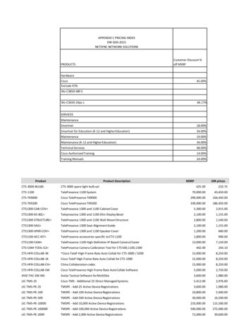
6. Device SpecifiicationF Type :Pointing FRONTFrontUnit : mmT Typpe : Pointingg TOPTTopmUnit : mm10
7. Connector Specification1) For Equipment (CTS-HCOM-AA01) : Slave, DSUB 25-pin, Pin Type, Maximumcable length is 10m.FunctionPin No.ColorFunctionPin No.ColorIN 11Red 1OUT 114Blue 1IN 22Red 2OUT 215Blue 2IN 33Red 3OUT 316Blue 3IN 44Red 4OUT 417Blue 4IN 55Green 1OUT 518White 1IN 66Green 2OUT 619White 2IN 77Green 3OUT 720White 3IN 88Green 4OUT 821Black 1NotConnected9XNotConnected22XSELECT10Yellow 3 VIN23RedMODE11 (GND)Yellow 2GND24BlackGo (Ready)12Black Red1)Serial Port(DSUB 9-pin, Female)Cable Connection Diagram1) Mode pin(11) is connected to GND inside so no additional connection is needed.11
2) For OHT (CTS-HCOM-AB01), Master Hirose 26-pin, 1.27mm IDE ConnectorFunctionPin No.ColorFunctionPin No.ColorIN 116BlackOUT 13Gray PinkIN 217BrownOUT 24Yellow BrownIN 318RedOUT 35White GrayIN 419YellowOUT 46Red BlueIN 520GreenOUT 57Gray BrownIN 621BlueOUT 68White GreenIN 722PurpleOUT 79White BlackIN 823GrayOUT 810White YellowSELECT14WhiteReady (Go)2White PinkMODE15Pink VIN12Brown GreenX11, 24XGND1Brown RedX25, 26XGND13White RedTxD1BlackRxD2BrownGND3RedDSUB 9-pin, femaleSerial PortMolex 4P(5557-04R)Molex 3P(51103-0300)Cable Connection Diagram12
AMP 12-pin, 172170A ConnectorFunctionPin No.ColorFunctionPin No.ColorIN 15Red 1OUT 16Blue 1IN 27Red 2OUT 28Blue 2IN 39Red 3OUT 310Blue 3IN 411Red 4OUT 412Blue 4SELECT3Yellow 3Ready (Go)4Black 2MODE2Yellow 2GND1WhiteCable Connection DiagramB ConnectorFunctionPin No.ColorFunctionPin No.ColorIN 51Green 1OUT 52White 1IN 63Green 2OUT 64White 2IN 75Green 3OUT 76White 3IN 87Green 4OUT 88Black 1X11X VIN9RedX12XGND10BlackCable Connection Diagram13
8. LED DisplayLED NameIN1 8OUTDisplay ContentIndicates the operation status of input circuit inside of PIO, which isON when the input is LOW.Indicates the output status inside of PIO, which is ON when TR is ON.Turns ON when there is data transmission/reception between amaster and a slave PIOs.GOThe maximum time that GO LED and output remain OFF afterthe wireless communication is disconnected is 775ms. This canbe adjusted by user through R command.Used as watchdog signal to check whether there is anabnormality in the product. RF mode: Blinks with periods of Master mode (0.25 sec),1)STATESlave mode (1 sec), standby mode (0.1 sec). IR mode : Similar to that of RF mode, but has differentblinking periods.※ Operation modes are distinguishable. See the diagram below.*) LED Diagram1) STATE LED Operation TimingModePeriod GraphSlaveIRMasterSlave2.4GMaster14
Slave5GMaster9. Major Pin FunctionSignal NameUsageMode (Input)Input to select a mode of PIO GND : Slave Mode (EQ, Connected to GND inside of PIO so noadditional connection is necessary.) OPEN : Master Mode (OHT)Select (Input)Input to operate the PIO GND : Stops a wireless communication of PIOs. OPEN : Operates a wireless communication of PIOs.GO (Output)Turns ON if there is a normal communication between a master and aslave PIOS. ModesMaster ModeSlave ModeTransmits data from input port wirelessly if PIO is operated byOPENing the Select signal. This mode is used by OHT or AGV.Even though PIO is operated by OPENing the Select signal, does nottransmit but only receives optical signals. Transmits data from inputport wirelessly when receives optical signals from the master. Thismode is used by equipment.15
10. Communication Medium Selecting MethodThis product has two contactless communication media: the optical (infrared light)and the wireless communication (2.4GHz, 5GHz RF). There can be a communicationinterference in the semiconductor factories because of surrounding equipment orsensors. If this happens, this product provides a stable communication by selectingthe other medium without an interference.A communication medium can be selected by the serial communication command(M command). In case of wireless communication (RF), the distinct channel ID andother variables must be set.16
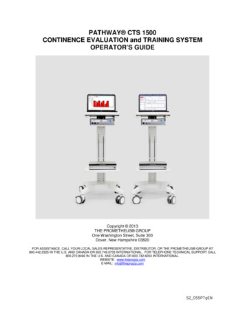
11. RF FunctionRF CommunicationCharacteristics RF communication using ISM (Industrial Scientific and Medical) Band of 2.4GHz and5GHz that can be used without an authorization. High-speed data communication - 1Mbps per channel. GFSK modulation, 1MHz bandwidth. A great expandability provided by the function selecting the serial numbers of 6bytes and frequencies of 3 bytes. Channel occupation time is about 1ms (Communication period: 25ms). Minimizesthe interference between other wireless devices. Setting the channel without conflict is necessary because of the frequencyinterference with 2.4GHz and 5GHz wireless LEN and other wireless devices. Maximum RF output power: 0dBm Sensitivity of the receiver : -90dBmAntenna Configuration2INSTA TEEmission Pattern17468135OUT7GO
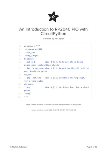
How to install These are the examples of the damping ratios depending on directions of themaster and slave PIOs in 10cm. See the values as the relative values with error ofmeasurement. Like the diagrams below, the reception sensitivity can be varydepending on the directions, even in such a short distance. This can influence theperformance of RF communication. Therefore, check the optimal conditions for RFcommunication before the installation of PIOs.DampingRatioInstallation Direction-25dB-30dB-18
DamptingRatioInstallation Direction-33dB--35dB--37dB-19
Precautions for Installation1) Metals, mirrors and other objects existing in a space at the straight-line distancebetween two sensors reduce the communication performance. Remove the obstacleson the path if possible.2) You can use it stably without communication errors when there is no interference withother wireless devices in an open space.3) There may be no metals or other obstacles within a 60mm radius around this antenna.4) There may happen frequency interference due to other RF devices around. Use this inan environment without frequency interference for stable operation.5)Especially, when using this together with a device using a 5GHz band, allocate achannel by avoiding overlaps.6) Maintain a 20cm or more interval between PIOs for equipment.Wireless Environment COMSeriescanbesimultaneously connected to many devices due to its characteristics. In order tocommunicate with one device (equipment), the ID and CH(channel) of thecommunication counterparty (For equipment, Slave PIO) shall be set before startingcommunication with the vehicle (OHT, Master PIO). The ID and CH setting is possibleusing serial communication commands.PIOSetting MethodSlave Connect to PIO serial port Set by a communicationcommands (ID and CH, transmission power etc.) The set data is stored in the memory, so it doesn’t needto be set again even though power is turned OFF.Master Connect to PIO serial port Set by a communicationcommands (No. of VHL/Communication Medium/ID/CH/PORT) In case of Select OFF(Communication Permitted) ON(Communication Prohibited), the IC and CH are changedto defaults. The No. of VHL, communication medium, ID,CH, PORT must be reset before Select OFF.※ If it is not ready for data transmission, it does nottransmit data even though it becomes Select OFF.※ For more information, see the Serial Communication Specification.12. IR Function20
IR CommunicationCharacteristics Wavelength : 870nm (Infrared light, Optical) Ambient brightness : 4000lx or less of incandescent light and fluorescent light,the place without direct light Transmission/reception method : Half Duplex Modulation : Pulse Modulation Operational distance and angle : 0.5m at 0 , 0.25m at 15 Adjustment of communication distance : Serial/RF communication command Adjustment of reception level : Serial/RF communication command(To eliminate surrounding noises if any.) Input signals and GO output filtering : Is possible to set the time by the serialcommand.IR RadiationCharacteristicsAs shown in the figure below, the communicable angle is 30 , andcommunication is possible from a 0.25m away distance at 15 and from a0.5m away distance at 0 . If light, sunshine, IR remote controller, opticalsensor, etc. applies light directly to the transmission/reception window, loss ofcommunication may happen. In this case, block the external light and then useit.Unit : mm21
Considerations for installationThis product uses both IR and RF communication. In case of IR (optical and infraredlight) communication, the performance declines if light is blocked by fixed brackets orparts since it uses invisible infrared light. As shown in the figure below, when PIOs ofVHL stop without error or within the range of 15 , surrounding objects shall not blockthe light of PIOs.Stop without errorStop at 15 degrees to the rightStop at 15 degrees to the leftThe cases of the light of PIO is blocked by the surrounding objects are shown indiagrams below. In these cases, there is high possibility of PIO communication errordepending on where VHL stops. If a VHL stops without error, the PIO communicationwill operate normally. However, if it stops with error, communication error can happenbecuse light is blocked. Therefore, be careful when install the fixed equipment andsurrounding devices.Stop without errorStop at 15 degrees to the rightStop at 15 degrees to the leftAlso, if there is optical noise, it is necessary to block the noise using the fixed objects.22
13. List of Serial Communication CommandsHow to set commands Serial Communication Setting Value: 38400,8,n,1, No flow control The first letter of every commands is “ ” and the last letter is “ ”. The first letter of responds for commands is “[“ and the last letter is “]”.Medium1)Master2)Slave2)Set the communication mediumIR/RFMaintainMaintainRThe number of trials forstable connectionIR/RFMaintainMaintainTSet the current timeIR/RFResetResetIR/RF--CommandMYFunctionCheck whether it is ready tocommunicateGCheck the GO statusIR/RF--LDownloadthe communication dataIR/RF(Function N/A)(Available)SDownload the status of thecommunication dataIR/RF(Function N/A)(Available)Check the versionIR/RF--RFResetMaintainVCANPWOSet the channelSet the IDRFResetMaintainSet the PORT numberRFResetUnusedIntensity of RF ainUnusedTime to check whetherthere are other devices.The number of OHT1) Whether to use the set values is dependent on media (optical or wireless)2) Whether to save the set values (If the set value is saved, it maintains this value eventhough the power is off.) is dependent on the mode (Master/Slave), so be careful whenuse serial commands.※ Use the serial communication program provided by CanTops to enter the commands. About A Serial Command Setting for Different ModesMaster ModeSlave ModeSetting the No. of OHT, communication medium, ID, CH, and No. ofPORT is only possible when SELECT is ON (Communicationprohibited). Other commands can be used at any time through theserial communication.Serial commands can be used at any time, regardless of SELECTstatus.※ See “Serial communication specification” for more detailed information.*) The specification of this product may change without notice to improve performanceof the product.* Rev Information23
DocumentVer.DateModified content Maximum value of Go signal: 375ms 775ms (p.11) Period of standby mode of STATE LED: 0.05 0.1초 Display the number of blinks of STATE LED depending on media- Only for IR : 3 timesV 1.02015.8.6- RF Mode, when IR operates : 5 times- RF Mode, when 2.4GHz operates : 7 times- RF Mode, when 5GHz operates : 9 times Modification in part of formats Addition of cable (Master) AMP for OHTV1.12015.9.7 Addition of the item number code formatV1.22016.1.8 Addition of the RF patterns and installation method depending onthe damping ratios. (p. 16, 17, 18 are added.)24
The CTS-HCOM Series is an integrated device that uses both RF communi-cation in 2.4GHz and 5GHz and IR (Infrared light, optical) communication. It is . VCE max. 100mV / 10mA RF-PIO Inside OUTPUT DCV PIO . 8 5. Product Specification Division Specifics Content Display GO