Transcription
Transformer Installation,Assembly & TestingW.J. (Bill) Bergman, M.Eng., P.Eng., LSMIEEEPowerNex Associates Inc.billBergman@pnxa.combergman@ieee.org 1-403-288-2148
Intent Provide explanations as to why certainprocess are important and should befollowed Describe some examples of what to do andwhat not to do Comments on my personal experiences? Provide references that you can study at yourleisure Answer questions2019-02-11 / 2019-02-12W.J. (Bill) Bergman, IEEE - Calgary / Edmonton2
Format of Presentation Ask questions Encourage discussion and understanding(especially on topics where there may bemore than one way or procedure to install atransformer). Please add your experiences. Please turn your cell phones OFF so we arenot distracted by texting, email, etc.2019-02-11 / 2019-02-12W.J. (Bill) Bergman, IEEE - Calgary / Edmonton3
2019-02-11 / 2019-02-12W.J. (Bill) Bergman, IEEE - Calgary / Edmonton4
Basis of Presentation Industry Accepted Practices; Based on IEEE and other consensus Guides Practical processes that are based on physics,chemistry and logic Based on others’ many years experience Personal Experience Have personally done this work on transformersfrom 10 to 750 MVA, 72 to 550 kV for 50 years(proving [to me] processes are possible & practical)2019-02-11 / 2019-02-12W.J. (Bill) Bergman, IEEE - Calgary / Edmonton5
Topics1. RECEIVING a transformer after transport toa substation site2. ASSEMBLY and PROCESSING of atransformer at site3. TESTING a transformer to verify itssuitability for service4. Discussion of integrating the transformerinto the power system2019-02-11 / 2019-02-12W.J. (Bill) Bergman, IEEE - Calgary / Edmonton6
Importance of Transformer Processes The way a transformer is handled and theprocedures that are used to receive, assemble,process and test the transformer are offundamental importance to the long life of thetransformer. The installation and testing of the transformerverifies its condition at the time it is ready forservice as well as forming the baseline or signaturetests for all future maintenance and later conditionassessment or analysis.2019-02-11 / 2019-02-12W.J. (Bill) Bergman, IEEE - Calgary / Edmonton7
2019-02-11 / 2019-02-12W.J. (Bill) Bergman, IEEE - Calgary / Edmonton8
2019-02-11 / 2019-02-12W.J. (Bill) Bergman, IEEE - Calgary / Edmonton9
2019-02-11 / 2019-02-12W.J. (Bill) Bergman, IEEE - Calgary / Edmonton10
2019-02-11 / 2019-02-12W.J. (Bill) Bergman, IEEE - Calgary / Edmonton11
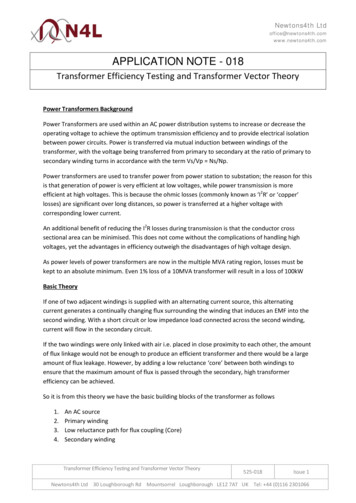
Transformer Condition TestsPossible ProblemMagnetic Circuit IntegrityMagnetic Circuit InsulationWinding GeometryWinding/Bushing/LTC ContinuityWinding/Bushing InsulationWinding Turn-to-Turn RatioElectrical TestDiagnostic TestWinding RatioXWinding ResistanceXMagnetizing CurrentXXCapacitance and DF/PFXInsulation ResistanceXCore Ground TestFrequency Response AnalysisXXXLeakage ReactanceDissolved Gas Analysis2019-02-11 / 2019-02-12XXXXXXXXW.J. (Bill) Bergman, IEEE - Calgary / EdmontonX12
Industry Standards & Guides Presented in the order of when they are usedin the transformer assembly and installationprocess Recognize that the transformer assembly andinstallation process starts much before thetransformer ever arrives on site2019-02-11 / 2019-02-12W.J. (Bill) Bergman, IEEE - Calgary / Edmonton13
Reference Standards and GuidesFactory CAN/CSA-C88-M90 (Reaffirmed 2009) “PowerTransformers and Reactors” IEEE Std C57.12.00 -2015 “IEEE Standard for GeneralRequirements for Liquid-Immersed Distribution, Power,and Regulating Transformers” IEEE Std C57.12.10 -2010 “Standard Requirements forLiquid-Immersed Power Transformers” IEEE Std C57.12.70 -2011 “IEEE Standard TerminalMarkings and Connections for Distribution and PowerTransformers” IEEE Std C57.12.90 - 2010 “IEEE Standard Test Code forLiquid-Immersed Distribution, Power, and RegulatingTransformers”2019-02-11 / 2019-02-12W.J. (Bill) Bergman, IEEE - Calgary / Edmonton14
Reference Standards and GuidesTransportation “Cargo Securement Rules” Federal Motor CarrierSafety Administration (North American) Cargo Securement – Driver’s Handbook on CargoSecurement – A Guide to the North American CargoSecurement Standard Responsibility of shipper and driver2019-02-11 / 2019-02-12W.J. (Bill) Bergman, IEEE - Calgary / Edmonton15
Reference Standards and GuidesTransportation and Site CIGRE 673 (WG A2.42) “Guide on TransformerTransportation” IEEE Std C57.150 -2012 “IEEE Guide for theTransportation of Transformers and ReactorsRated 10 000 kVA or Higher”2019-02-11 / 2019-02-12W.J. (Bill) Bergman, IEEE - Calgary / Edmonton16
Reference Standards and GuidesSite IEEE Std C57.93 -2007 “IEEE Guide for Installation andMaintenance of Liquid-Immersed Power Transformers” CAN/CSA-C50-08 (R2013) “Mineral insulating oil,electrical, for transformers and switches” IEEE Std C57.106 -2015 “IEEE Guide for Acceptanceand Maintenance of Insulating Oil in Equipment” IEEE Std C57.152 -2013 “IEEE Guide for DiagnosticField Testing of Fluid-Filled Power Transformers,Regulators, and Reactors” IEEE Std C57.149 -2012 “IEEE Guide for the Applicationand Interpretation of Frequency Response Analysis forOil-Immersed Transformers”2019-02-11 / 2019-02-12W.J. (Bill) Bergman, IEEE - Calgary / Edmonton17
Other Standards & Guides of Interest ¼Accessories CAN/CSA C88.1-96 (Reaffirmed 2011) PowerTransformer and Reactor Bushings“ IEEE Std C57.19.01 -2000 “IEEE StandardPerformance Characteristics and Dimensions forOutdoor Apparatus Bushings” IEEE Std C57.131 -2012 “IEEE Standard Requirementsfor Load Tap Changers” CAN/CSA-C60044-1-07 (R2011) - InstrumentTransformers - Part 1: Current Transformers (IncludesCSA C13) IEEE Std C57.13.1 -2006 “IEEE Guide for Field Testingof Relaying Current Transformers” IEEE Std C57.13.3 -2014 “IEEE Guide for Grounding ofInstrument Transformer Secondary Circuits and Cases”2019-02-11 / 2019-02-12W.J. (Bill) Bergman, IEEE - Calgary / Edmonton18
Other Standards & Guides of Interest 2/4Operating Condition IEEE Std C57.104 -2008 “IEEE Guide for theInterpretation of Gases Generated in Oil-ImmersedTransformers” IEEE Std PC57.104 - [2018 November] Unapproved “DraftGuide for the Interpretation of Gases in Oil ImmersedTransformers” IEEE C57.91 -2011 “IEEE Guide for Loading MineralOil-Immersed Power Transformers and Step VoltageRegulators”2019-02-11 / 2019-02-12W.J. (Bill) Bergman, IEEE - Calgary / Edmonton19
Other Standards & Guides of Interest 3/4Specialized Transformers IEEE std C57.116 -2014- "IEEE Guide forTransformers Directly Connected to Generators“ IEEE Std C57.21 -2008 “IEEE StandardRequirements, Terminology, and Test Code forShunt Reactors Rated Over 500 kVA” IEC 62032 / IEEE C57.135 -2005 “Guide for theapplication, specification, and testing of phaseshifting transformers”2019-02-11 / 2019-02-12W.J. (Bill) Bergman, IEEE - Calgary / Edmonton20
Other Standards & Guides of Interest 4/4IEC IEC 60076 (Power transformers Parts 1 through 21) EC 60076-1 ed3.0 General IEC 60076-8 ed1.0 Application guide IEC 60214-1 Tap-changers - Part 1: Performancerequirements and test methods IEC 60137 Insulated bushings for alternatingvoltages above 1 000 V2019-02-11 / 2019-02-12W.J. (Bill) Bergman, IEEE - Calgary / Edmonton21
Information Required for Installation Presented generally in the order that theinformation is produced.2019-02-11 / 2019-02-12W.J. (Bill) Bergman, IEEE - Calgary / Edmonton22
Customer InformationSpecification and Change Orders Purchaser’s transformer specification(s)(general and rating/data specifications) Purchase order and change orders that mayinfluence technical considerations wheninstalling the transformer (unpriced).2019-02-11 / 2019-02-12W.J. (Bill) Bergman, IEEE - Calgary / Edmonton23
Customer & Factory InformationDesign Review Explanations, commitments, clarificationsand notes from the design review meeting Recommended to be conducted- by a transformer expert at the factory- in accordance with CIGRE- Publication 529 “Guidelines for ConductingDesign Reviews for Power Transformers”, and- Publication 673 “Guide on transformertransportation”2019-02-11 / 2019-02-12W.J. (Bill) Bergman, IEEE - Calgary / Edmonton24
Factory Information – DocumentationRelated to Receiving Transport and handling drawing Receiving instructions (in instruction manual?) Assembly instructions (in instruction manual?) Pre-Transport test results Photographs of transformer loaded on carrier Detailed packing lists should indicate individualparts in each package/crate Final drawings2019-02-11 / 2019-02-12W.J. (Bill) Bergman, IEEE - Calgary / Edmonton25
Factory Information – Testing(Related to Transport & Receiving) Core and clamp insulation Megger tests (withcorrect Megger voltage at core ground testterminal) Leak test results Transport gas pressure and dew point tests Shock recorder settings and information andaccessories required to interpret results FRA tests in Fully assembled and oil filled condition, and/or Transport condition with test bushings2019-02-11 / 2019-02-12W.J. (Bill) Bergman, IEEE - Calgary / Edmonton26
Factory Information – Testing(Related to site testing)Factory test report Winding & bushing insulation resistance, PF (powerfactor) & capacitance Winding ratios Polarity Winding resistance (demagnetize after) Low voltage excitation current Single-phase excitation test Other2019-02-11 / 2019-02-12W.J. (Bill) Bergman, IEEE - Calgary / Edmonton27
Factory Information –(Required for Installation) Factory drawings Factory test report(s) Instruction manual(s) Photographs of assembled or partially assembledtransformer (at factory) Substation foundation, bus, station service,grounding, protection & control , and SCADAdrawings2019-02-11 / 2019-02-12W.J. (Bill) Bergman, IEEE - Calgary / Edmonton28
Transformer Warranty Considerations 1 of 2 Inspections and receiving “Proper” (and sometimes supervised) assembly,processing, & testing of transformer Adherence to manufacturer’s or industry protocolsfor assembly, processing, & testing Acceptable test methods and results Adequate records2019-02-11 / 2019-02-12W.J. (Bill) Bergman, IEEE - Calgary / Edmonton29
Transformer Warranty Considerations 2 of 2 Manufacturer, as a condition of warranty, almostalways want their representative on site when the transformer arrives. (Megger andimpact recorder reading), and during some portions of installation (e.g.installing bushings, internal inspection, etc). Owners should always give a manufacturer theoption to come to site (even if the manufacturerdoesn't require it).2019-02-11 / 2019-02-12W.J. (Bill) Bergman, IEEE - Calgary / Edmonton30
Transformer Installation Records Assembly log indicating dates/times and weatherconditions, people during entire process Records of all inspections and testing (ratioincluding phase angle and current, Megger ,excitation current and voltage, insulation powerfactor and capacitance of windings and bushings,FRA, other dielectric tests, oil physical and DGAtests including sampled location(s), functional tests(and methods) on all accessories, etc.)2019-02-11 / 2019-02-12W.J. (Bill) Bergman, IEEE - Calgary / Edmonton31
Transformer Receiving2019-02-11 / 2019-02-12W.J. (Bill) Bergman, IEEE - Calgary / Edmonton32
Transformer Receiving Safety Be aware of Terms of Transport INCOterms Understand point of transfer of ownership as wellas warranty obligations Understand point of transfer of responsibility Assess Condition of Transformer2019-02-11 / 2019-02-12W.J. (Bill) Bergman, IEEE - Calgary / Edmonton33
INCOterms 2010 RULES FOR ANY MODE OR MODES OF TRANSPORT EXW EX WORKS DAT Delivered At Terminal DAP Delivered At Place DDP Delivered Duty Paid RULES FOR SEA AND INLAND WATERWAYTRANSPORT FAS Free Alongside Ship FOB Free On Board CFR Cost and Freight CIF Cost Insurance and Freight2019-02-11 / 2019-02-12W.J. (Bill) Bergman, IEEE - Calgary / Edmonton34
Transformer Receiving - Acceptance Assess Condition of Transformer Importance of knowing condition whentransformer left the factory to allowcomparison. Compare ex-factory condition to asreceived conditions to determine changethat could be caused by transport orstorage. Testing and inspection2019-02-11 / 2019-02-12W.J. (Bill) Bergman, IEEE - Calgary / Edmonton35
Transformer Receiving – Safety Transport gas could be N2 or air – test for lifecompatibility (O2), absence of combustible gas,absence of CO or CO2 Working at height (especially when receivingtransformer on transporter). Appropriate fallarrest, falling objects prevention, ladder andelectrical safe work practices. Confined space entry and extraction. Be aware of loose or broken parts, crates, etc.2019-02-11 / 2019-02-12W.J. (Bill) Bergman, IEEE - Calgary / Edmonton36
2019-02-11 / 2019-02-12W.J. (Bill) Bergman, IEEE - Calgary / Edmonton37
Transformer - Unloading Is foundation in condition to receive transformer?[Size, shape, capacity, flat, level, cured, condition,etc.] Use of crane and slings [transport condition vs. fullyassembled condition] Use of jack and slide [jacking, blocking, slide areas] Transport drawing, markings on tank and parts Concentrated loading on tank bottom?2019-02-11 / 2019-02-12W.J. (Bill) Bergman, IEEE - Calgary / Edmonton38
Transformer Receiving – Visual Inspection Visual inspection for security/tightness ofattachments to transporter, movement ontransporter, damage caused by securement,collisions with other objects or vibration orimpact(s) Positive pressure on transport gas gauge Absence of shock or vibration recording on shockrecorder and confirmation that shock recorder isstill functioning Visual inspection of accessories to verify arrival inundamaged condition and shipment is complete2019-02-11 / 2019-02-12W.J. (Bill) Bergman, IEEE - Calgary / Edmonton39
Transformer Receiving – Testing Visual Inspection Transformer transport gas pressure (positivepressure or sustained negative pressure) and dewpoint (correct for temperature and pressure) Core and clamp insulation (with correct voltage ofMegger (also correct for temperature) Shock (electronic) recorder assessment (Use CIGRE673) FRA test if other indications of possible damage2019-02-11 / 2019-02-12W.J. (Bill) Bergman, IEEE - Calgary / Edmonton40
Transformer Assembly2019-02-11 / 2019-02-12W.J. (Bill) Bergman, IEEE - Calgary / Edmonton41
Transformer Safety – People Working at height (especially when receivingtransformer on transporter). Appropriate fallarrest, falling objects prevention, ladder andelectrical safe work practices. Confined entry plan and process, extraction? Transport gas could be N2 or air – test forpressure, (before opening manhole), lifecompatibility O2, absence of combustible gasand absence of CO or CO2.2019-02-11 / 2019-02-12W.J. (Bill) Bergman, IEEE - Calgary / Edmonton42
Transformer Safety – Transformer Minimize people entry into transformer Minimize entry of moisture into transformer Maintain dry air environment Bond and ground the transformer, all bushings, oilhoses, oil filtering and vacuum equipment. Vacuum and oil processing only above 10 C Perform leak-down vacuum test prior to vacuumand oil processing No electrical testing during vacuum stages2019-02-11 / 2019-02-12W.J. (Bill) Bergman, IEEE - Calgary / Edmonton43
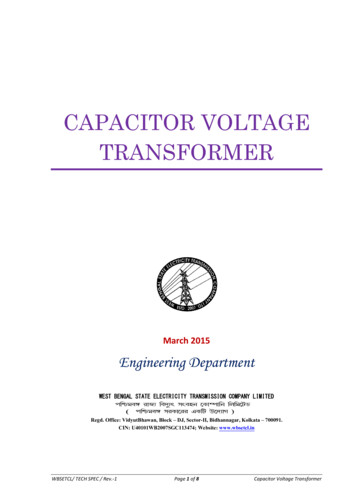
Paschen Curve: Voltage Breakdown vs Pressure2019-02-11 / 2019-02-12W.J. (Bill) Bergman, IEEE - Calgary / Edmonton44
Transformer Assembly Cleanliness is very important! Ensure parts are “naturally” aligned rather thanforce fit. (It went together in the factory) Importance of care in installing (new) gaskets duringassembly. Ensure correct gasket is used to maintaincompression ratio for the specific material. Use correct torque for each size of bolt. Confined entry plan and process2019-02-11 / 2019-02-12W.J. (Bill) Bergman, IEEE - Calgary / Edmonton45
Transformer Assembly – Sequence Make sure all components, parts and oil are on siteand in good condition. Test oil to meet kV, IFT, Neut. No., PF (25 C &100 C) as per IEEE C57.106 as a minimum beforeallowing oil to enter the tank or accepting new oilfrom a tanker Ensure safe internal atmosphere and dry ( 50 C)breathable air is available while transformer isopen. Assemble ladder, conservator, cooling equipment,piping, bushings, cabinets, and some monitoring.2019-02-11 / 2019-02-12W.J. (Bill) Bergman, IEEE - Calgary / Edmonton46
Transformer Assembly - Bushings Test cleaned bushings prior to installation (PF, C1,C2) Install cleaned bushings with new gaskets, correcttorque on current carrying connections, properprocedure for draw lead or draw rod connectedbushings. Confirm whether the capacitance tap is to beoperated in grounded or ungrounded mode. Install bushing monitoring devices, if applicable.2019-02-11 / 2019-02-12W.J. (Bill) Bergman, IEEE - Calgary / Edmonton47
Transformer Assembly – Components Make sure that piping, conservator tank, coolingequipment, etc. has been shipped in a sealedcondition so that no water, dirt, or other foreignmaterial is inside. Check that the insides of all accessories are clean.2019-02-11 / 2019-02-12W.J. (Bill) Bergman, IEEE - Calgary / Edmonton48
Transformer Assembly – Conservator Make sure conservator tank(s) are clean. Check both sides of conservator tank (someconservators are compartmentalized for LTC andmain transformer oils). Install bladder while conservator on ground. Makesure there is provision to prevent a collapsedbladder from blocking the pipe to the transformer. Install piping to main tank (including Buchholz relay)so there is no strain on the GDR.2019-02-11 / 2019-02-12W.J. (Bill) Bergman, IEEE - Calgary / Edmonton49
Transformer Assembly - Cooling Install radiators or coolers (and pumps) Ensure valves operate correctly Ensure all bracing and seismic reinforcing areinstalled Temperature gauge calibration?2019-02-11 / 2019-02-12W.J. (Bill) Bergman, IEEE - Calgary / Edmonton50
Transformer Processing2019-02-11 / 2019-02-12W.J. (Bill) Bergman, IEEE - Calgary / Edmonton51
Why Process Oil & Insulation? In factory, cellulose insulation is dried to 0.5 % water(by weight) to achieve optimum dielectric performancefor factory testing. When the active part (core & coils &leads) is removed from vapour-phase process, it startsto regain moisture from air and from oil [water movesrelatively easily oil cellulose but with relativedifficulty from cellulose oil. Moisture in celluloseshortens the life of the insulation. Moisture enters transformer during assembly. If moisture content of oil is low, less moisture can moveinto the cellulose insulation. Ability of oil to hold dissolved moisture decreases astemperature goes down [saturation must be avoided].2019-02-11 / 2019-02-12W.J. (Bill) Bergman, IEEE - Calgary / Edmonton52
Effect of Moisture on Insulation Can cause Failures Lowers dielectric strength of insulation Can generate gas bubbles above certaintemperature ( 140 C) Can initiate partial discharge Shortens insulation life2019-02-11 / 2019-02-12W.J. (Bill) Bergman, IEEE - Calgary / Edmonton53
How to Remove Moisture from Transformer? Easier to keep moisture out than to remove it. Easier to move moisture from cellulose to oil athigher temperatures [applied heating or in-service] Applying vacuum [lowering absolute pressure]allows the partial pressure of water [loweringboiling point of water] making it move out ofcellulose.2019-02-11 / 2019-02-12W.J. (Bill) Bergman, IEEE - Calgary / Edmonton54
Estimating Moisture Content in InsulationEstimate from moisture in air or in oil Difficulty in knowing exact insulation and oiltemperature. Equilibrium between oil and insulation hastime based limitations. Equilibrium is rarely achieved Time constant is different for moisture into orout of paper Moisture unevenly distributed in insulation Equilibrium curves dependent on specific oiltype/standard.2019-02-11 / 2019-02-12W.J. (Bill) Bergman, IEEE - Calgary / Edmonton55
Oommen’s Curves for Moisture Equilibrium Paper-Oil2019-02-11 / 2019-02-12W.J. (Bill) Bergman, IEEE - Calgary / Edmonton56
Oommen curves forLow Moisture Equilibrium – Paper-Oil2019-02-11 / 2019-02-12W.J. (Bill) Bergman, IEEE - Calgary / Edmonton57
Griffin Curves for Water Equilibrium inCellulose/Mineral Oil Systems2019-02-11 / 2019-02-12W.J. (Bill) Bergman, IEEE - Calgary / Edmonton58
Paper-Oil Moisture References T.V. Oommen (Westinghouse, ABB), “MoistureEquilibrium Charts for Transformer Insulation DryingPractice”, IEEE Transactions on Power Apparatus andSystems, Vol. PAS-103, No. 10, October 1984 Y.Du, M. Zahn, B.C. Lesieutre, and A.V. Mamshev (MIT)and S.R. Lindgren (EPRI) “Moisture Equilibrium inTransformer Paper-Oil Systems”, IEEE ElectricalInsulation Magazine, January/February 1999 – Vol. 15,No. 1 T.V. Oommen, J. Thompson and B. Ward, “MoistureEstimation in Transformer Insulation”, IEEETransformers Committee Panel Session, March 9, 2004,Sponsored by the Insulating Fluids Subcommittee2019-02-11 / 2019-02-12W.J. (Bill) Bergman, IEEE - Calgary / Edmonton59
Transformer Vacuum Processing2019-02-11 / 2019-02-12W.J. (Bill) Bergman, IEEE - Calgary / Edmonton60
Vacuum Cautions (ref. IEEE C57.93)a) Ensure the transformer tank and all fittings are suitable forvacuum, including:1) Conservator tank (tank and bladder, if equipped, have to bepressure-equalized)2) Radiators, pumps, and their valvesIf any of these fittings are not designed to withstand vacuum, theyneed to be removed or valved off.b) Ensure the LTC is suitable for vacuum or has its pressureequalized.c) Ensure instrumentation is suitable for vacuum (older combustiblegas sensor units must not only be isolated but usually removedfrom the transformer during application of a vacuum).d) Ensure no additional structure load is to be put on top of thetransformer under vacuum (such as people!, lifting, jacking, etc.)2019-02-11 / 2019-02-12W.J. (Bill) Bergman, IEEE - Calgary / Edmonton61
Transformer Vacuum – Sequence Install blanking plate on PRD. * Pressure test ( 5 psi gauge) and monitor. Ensure vacuum equalizing piping is installed orvalves are open. Apply vacuum to about 100 Pa (0.75 Torr) (0.75 mmHg) to remove surface moisture and perform “leakdown” test.*Note: PRD is usually removed during vacuumprocessing. An adapter to use the PRD flange or aseparate flange on the cover is used to drawvacuum on the tank.No electrical testing while under vacuum (10 V PF)2019-02-11 / 2019-02-12W.J. (Bill) Bergman, IEEE - Calgary / Edmonton62
Paschen Curve: Voltage Breakdown vs Pressure2019-02-11 / 2019-02-12W.J. (Bill) Bergman, IEEE - Calgary / Edmonton63
Transformer Vacuum Processing Vacuum and oil processing only above 10 C Perform “leak-down” vacuum test prior to vacuumand oil processing IEEE Std C57.106 Oil entry into transformer only when oil can beassured of meeting IEEE Std C57.106 “IEEE Guidefor Acceptance and Maintenance of Insulating Oil inEquipment”2019-02-11 / 2019-02-12W.J. (Bill) Bergman, IEEE - Calgary / Edmonton64
Vacuum Leakage NOTE 1— Any air leakage into the transformer tank,while a vacuum is being drawn on the transformer,may seriously contaminate the transformerinsulation. Air, when drawn into a vacuum, expandsand drops in temperature, consequently releasingmoisture. If the core and coils are cold, the moisturereleased from the air will condense on these partsand will be absorbed into the paper insulation.Ref: IEEE C57.93 clause 4.8.1 Preparation2019-02-11 / 2019-02-12W.J. (Bill) Bergman, IEEE - Calgary / Edmonton65
Vacuum “Leak Down” Test – Method B Two pressure readings; 60 min & 90 min after the vacuum valveon pump is closed, first 60 min allows de-absorption of gassesfrom insulation. Where V is the volume of oil of the transformer tank in litres. Leakage 150 mm Hg litres/minute equivalent to 20 m3Pa/min If leakage rate exceeds 20 m3Pa/min, corrective action to retighten all mounting bolts & fittings and/or application ofsealant to suspected fittings is required. If satisfactory, openthe main vacuum valve and repeat the evacuation until vacuumcondition is stable or below 50 Pa. Repeat the pressure riserecording, extending the recording an additional four readingsat five-minute intervals.Ref: IEEE C57.93 clause 4.8.32019-02-11 / 2019-02-12W.J. (Bill) Bergman, IEEE - Calgary / Edmonton66
Allowable Vacuum Leak Evacuate the transformer to about 100 Pa. Close themain vacuum valve between the transformer tank andthe vacuum pumping system. New transformers can generally withstand a mass leakrate of 20 m3Pa per minute Note: the larger the transformer the lower pressurerise allowed.2019-02-11 / 2019-02-12W.J. (Bill) Bergman, IEEE - Calgary / Edmonton67
Maximum Allowable Moisture New 500 kV – less than 0.5% by weight New 69 to 230 kV – less than 0.8% by weight Ex: 450 MVA, 245-20 kV two-winding transformerweighs 250T Core & coils 125T of which 25T is cellulose At 2% water, there is 500 kg of water in theinsulation. To achieve recommended 0.5% moisturecontent, 375 kg of water must be removed(hopefully most at the factory!).2019-02-11 / 2019-02-12W.J. (Bill) Bergman, IEEE - Calgary / Edmonton68
When is Insulation Dry? Allowable moisture content is dependent onvoltage class. No direct method to measure moisture. Moisture measured by: Gas dew point measurement Monitor moisture in exhaust gas of vacuum pump[weigh ice in trap] Very Low voltage (during vacuum processing)measurement of insulation dissipation factor orpower factor2019-02-11 / 2019-02-12W.J. (Bill) Bergman, IEEE - Calgary / Edmonton69
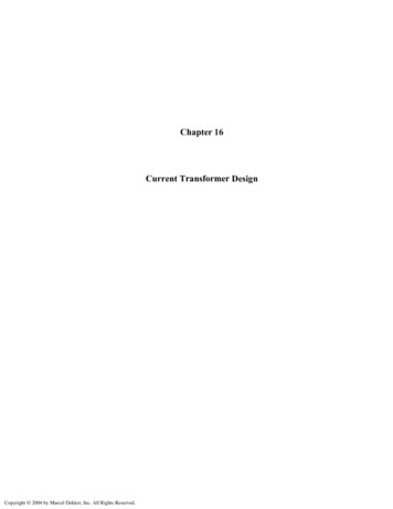
Insulation Dryness Example On Figure B.1, read the vapor pressure as 100 m(13.3 Pa). Correct vapor pressure to tankconditions. On Figure B.2, read the moisture content 0.75% ofthe dry weight of insulation at the junction of 114 m (15.2 Pa) vapor pressure and the insulationtemperature of 20 C2019-02-11 / 2019-02-12W.J. (Bill) Bergman, IEEE - Calgary / Edmonton70
Conversion dew point to vapor pressureRef: IEEE C57.93, Figure B.12019-02-11 / 2019-02-12W.J. (Bill) Bergman, IEEE - Calgary / Edmonton71
Moisture Equilibrium ChartRef: IEEE C57.93, Figure B.22019-02-11 / 2019-02-12W.J. (Bill) Bergman, IEEE - Calgary / Edmonton72
Oil Sampling and Testing2019-02-11 / 2019-02-12W.J. (Bill) Bergman, IEEE - Calgary / Edmonton73
Transformer Oil Sampling - Standards ASTM D 923 – 97 “Standard Practices for Sampling ElectricalInsulating Liquids” ASTM D 2759 – 00 “Standard Practice for Sampling Gas from aTransformer Under Positive Pressure” ASTM D117 - 10 ”Standard Guide for Sampling, Test Methods, andSpecifications for Electrical Insulating Oils of Petroleum Origin” ASTM D 3305 – 94 “Standard Practice for Sampling Small GasVolume in a Transformer” (This practice is used for sampling gasfrom a transformer gas space or from a gas-collector relay wherethe volume of gas available is small and will not permit the use ofPractice D 2759.) ASTM D 3613 – 98 “Standard Practice for Sampling InsulatingLiquids for Gas Analysis and Determination of Water Content” IEC 60475 ed2.0 (2011-10) “Method of sampling insulatingliquids”2019-02-11 / 2019-02-12W.J. (Bill) Bergman, IEEE - Calgary / Edmonton74
Transformer Oil Sampling - Sensitivity Test results for dielectric strength and watercontent are significantly affected by samplingtechnique! Dissolved gas-in-oil analysis is another testimpacted by sampling, sample valve components,contamination or residue, ineffective sample andsampling materials. Clean, flush, store/transport Sampling method is important!!!2019-02-11 / 2019-02-12W.J. (Bill) Bergman, IEEE - Calgary / Edmonton75
2019-02-11 / 2019-02-12W.J. (Bill) Bergman, IEEE - Calgary / Edmonton76
Transformer Acceptance Testing Comparison or field tests with factory tests Conformance with industry criteria including IEEEStds C57.93 and C57.106 Customer and/or manufacturer may haveacceptance limits for test results and methods CSA-C88 Table 9 provides limits for tolerance onfactory tests of ratio, impedance (Z1, Z0), excitationcurrent, losses2019-02-11 / 2019-02-12W.J. (Bill) Bergman, IEEE - Calgary / Edmonton77
Transformer Testing - IEEE C57.93 (1/3)IEEE C57.93 Clause 4.11 Tests after the transformer has been assembledand filled with dielectric liquida) Insulation resistance test on each winding to groundand between windings.b) Insulation power factor or dissipation factor test oneach winding to ground and between windings.Capacitance should also be measured on eachconnection. In addition, core insulation should alsobe tested.c) Power factor or dissipation factor test on allbushings equipped with a power factor tap orcapacitance tap. Both C1 and C2 insulation shouldbe measured. NOTE—If final bushings are not usedin the factory, test results may differ.d) Check operation of liquid-level and hot-spottemperature indicating and control devices.2019-02-11 / 2019-02-12W.J. (Bill) Bergman, IEEE - Calgary / Edmonton78
Transformer Testing - IEEE C57.93 (2/3)e) Winding ratio test on each tap. If LTC transformer,check winding ratio on all LTC positions.f) Check dissolved gas, dielectric strength, powerfactor, interfacial tension, neutralization number,and water content of the dielectric liquid.g) Check oxygen content and total combustible gascontent of nitrogen gas cushion in sealed tanktransformers. A total combustible gas test, whereapplicable, and a dissolved gas-in-oil test of thedielectric fluid should also be made soon after thetransformer is in service at operating temperatureto provide a suitable post-energization reference“bench mark.”2019-02-11 / 2019-02-12W.J. (Bill) Bergman, IEEE - Calgary / Edmonton79
Transformer Testing - IEEE C57.93 (3/3)h) Check polarity and excitation current at reduced t
Discussion of integrating the transformer into the power system 2019-02-11 / 2019-02-12 W.J. (Bill) Bergman, IEEE - Calgary / Edmonton 6. Importance of Transformer Processes The way a transformer is handl