Transcription
The Design, Manufacture and Test of a LiquidPropellant Aerospike Rocket EngineSubmitted to the 2002 Engineering Student Design CompetitionJune 14, 2002
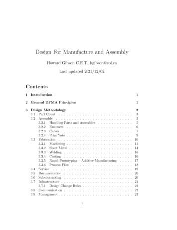
1.0 Introduction1.1 The advantage of Spike Shaped Nozzles vs. conventional bell-shaped nozzlesIn a conventional bell-shaped nozzle, combustion gases flow through aconstriction (throat) and then expand away from the centerline. The diverging walls ofthe nozzle up to the exit plane contain the expanded gases. Bells nozzles are a pointdesign with optimum performance at one specific pressure, i.e. altitude. Careful design isneeded to achieve desired high altitude performance while avoiding flow separation at thewalls of the nozzle near the exit when operating at low altitudes, which can lead to loss ofperformance and possible structural failure of the nozzle due to dynamic loads.Contrary to a bell-shaped nozzle, the gas flow of a spike nozzle is directedradially outward from an annulus at some diameter away from the centerline. This flow isdirectly exposed to ambient pressure and it expands to the external environment,providing continuous altitude compensation. This compensation allows for little loss ofthrust at off-design altitudes, and safer dynamic loads at start-up.Figure 1-Spike nozzle flow fields at various atmospheric pressures
Figure 2-Conventional nozzle flow fields at various atmospheric pressures1.2 TruncationThe ideal spike is truncated to save engine mass and required cooling area. Thistruncation results in a wake at the base of the spike, which induces some losses inperformance. However, this can be offset by pumping secondary flow (about 1% ofprimary flow) into the base region to elongate the wake, thus forming an aerodynamiccontour similar to the truncated structure (hence the name "aerospike").1.3 History of the AerospikeThe aerospike concept is particularly advantageous for developing single stage toorbit (SSTO) vehicles due to its high efficiency at various altitudes. Aerospike engineswere investigated by Rocketdyne in the 1960's, and then again as part of the nowcancelled X-33 program. As part of the latter, Boeing Rocketdyne developed the RS2200, a linear aerospike that was static fired several times. However, after more than fourdecades of research, no aerospike engine is known to have powered a rocket in flight.1.4 How thrust is producedAn important equation, derived from the conservation of momentum, helps tounderstand what influences the thrust of a rocket engine (eq. 1): FThrust m Vex Aexi t ( Pexit Patm )(eq. 1)
Figure 3 The term m is the mass flow rate of the propellants, which is controlled by the orificesizes in the injector. The velocity of the exhaust gases, Vex , is a function of the area ofthe nozzle’s throat and how the nozzle performs. The cross-sectional area of the nozzleat the exit, Aexit , is found by determining the area needed to expand the exhaust gases sothat the exit pressure is equal to the atmospheric pressure at the design altitude. Ingeneral, Pexit , the pressure of the gases at the exit of the nozzle differs from Patm , theambient pressure around the rocket engine at its given altitude. The design of the rocketengine’s injector, combustion chamber, and nozzle has an effect on all of these terms.1.5 Objectives of the projectThe goal of flying the first aerospike-powered rocket was taken on as the seniordesign project for the Aerospace System Design I & II course. Through the state-fundedCalifornia Launch Vehicle Education Initiative (CALVEIN), and with help fromaerospace professionals, students were set to develop a 1000 lbf annular, ablativeaerospike rocket engine using liquid oxygen (LOX) as the oxidizer and ethanol as thefuel. Over the course of two semesters the initial requirements were flowed downthroughout all of the components of the aerospike engine, shaping the final design. Oncebuilt and flight qualified through a static fire, the first powered flight of an Aerospikeengine would take flight on the already developed Prospector-2 rocket (also built bystudents).In the following sections the design process, manufacturing, and testing of theaerospike engine will be described and the results shown.2.0 Design Process2.1 RequirementsThe process of designing the engine was the most arduous phase of developmentbecause the initial design requirements, which are the desired thrust of the engine, the
propellants that would be used, and the use of an aerospike for a nozzle, had to beconsidered. Because the engine would be integrated to the Prospector-2 rocket, the use ofdenatured ethanol and liquid oxygen (LOX) for propellants, and a maximum tankpressure of 390 psi were already determined. One of the initial requirements specifiedthat the engine must burn for a duration of 6 seconds. This created the need for sometype of cooling on the walls of the combustion chamber and the spike. The decision wasmade to use film cooling on these surfaces.2.2 Design Drivers and Preliminary DesignThe main design driver was the configuration of the injector(s) with respect to theaerospike element. In the past, most aerospike engines incorporated an array of thrustersaround the spike element, mainly to prevent combustion instabilities. In order todecrease manufacturing time and the complexity of plumbing, it was decided that thespike element would be attached to the face of one injector as shown in Figure 4.Figure 4-CAD model of aerospike engine designed, built and testedSince erosion rates at the throat of the nozzle would hinder the efficiency of theengine, steps had to be taken to minimize this. Because of its higher melting point, andbetter tolerance to heat, the spike and the ring creating the throat were made out ofgraphite. The ability to provide film cooling on both the rod and chamber wall was alsoimportant. Therefore, a dual-triplet injector with film cooling was utilized.2.3 Injector DesignBecause of the layout of the spike element being attached to the face of theinjector Figure 4, and the high erosion rates of ablative materials, a dual triplet injectorwith film cooling was most desirable configuration.
Figure 5-Dual Triplet Hole Pattern, with Film-CoolingOnce an injector type is chosen, the sizing of the orifices is achieved with thefollowing procedure. Producing 1,000 lbf of thrust and using a fuel and oxidizercombination of LOX and ethanol are requirements. Given a propellant mixture ratio,reference tables can be consulted to determine the value of the specific impulse. Withthis data the total weight flow rate can be calculated: F1000lbfω total 4.166667lbf / sec (eq. 2)I sp240 secThe oxidizer/fuel (O/F) ratio used is based on equal volume of oxidizer and fuel, whichallows the use of identical tanks for the fuel and oxidizer. With equal volumes, the ratioof the density of LOX to the density of ethanol reduces to the mass ratio, which is equalto approximately 1.43. The O/F ratio allows the calculation of the weight flow rate of theoxidizer and fuel: ωox ω*r4.166667 * 1.43 2.451989lbf / sec (eq. 3)1 r2.43 ωtotalfuelω total4.166667 1.714678lbf / sec (eq. 4)1 r2.43Film cooling flow rates were calculated under the assumption of 30% of the fuel flowallocated to film cooling. A value of 30% was based on past experience using filmcooling. 20% of the flow would be concentrated on the outer wall of the combustionchamber, and 10% would be concentrated on the rod, in the center of the combustionchamber. To attain the correct flow rates the injector holes were sized to account for theloss of flow.w filmcooling .30 w fuel (eq. 5)Orifice areas can then be calculated with the following equation: ω(eq. 6)ω Cd * A * 2 * g * p * ρ A Cd * 2 * g * p * ρ
Where Cd coefficient of dischargeA Total area of the injector holesG gravity P Change in Pressureρ density of fluidw Weight flow rate2.4 Combustion ChamberThe second major subsystem of a rocket engine is the combustion chamber. Thetemperature of combustion of the burning propellants is extremely high, approximately5300 degrees Fahrenheit. This is above the melting temperature of common alloys andtherefore thermal insulation must be used to protect any metal surfaces. An ablativelining made from silica cloth and phenolic resin is a cost effective and easy to obtainsolution. This lining is a thermal barrier, which absorbs much of the heat by thermallydecomposing in an endothermic reaction, and releasing gasses that carry conducted heataway. It also provides oxidation protection by forming a thin layer of molten glass overthe surface of the char.Again, past aerospike engines were designed with several combustion chambersin order to prevent combustion instabilities. However, since this design is at a muchsmaller scale, a single chamber configuration was chosen and the spike attached to theface of the injector.The combustion chamber was sized according to three separate requirementsflowed-down from the top-level requirements. These included an L* of 50 in, where L*is a characteristic length and is assumed by pervious experience of engine sizing, leadingto a chamber volume of 111.48 in 3 using equation 7 from below, and a chamber pressureof 300 psi.Vc A * L * (eq. 7)**where A is the throat area and L is the chamber characteristic length. The chamberpressure is based on tank pressure and the P across the injector. The propellant tankswere tested at pressures up to 500 psi. This value was one of the major drivers behind thefinal sizing of the chamber.Knowing the volume of the chamber allowed for the overall sizing to take place.To find the best sizing for our engine, many factors came into play. The first of thesewas the diameter of the rod that held the spike in place. This diameter was set at 2 inchesfor structural reasons. The diameter of the chamber had to take into account enoughroom for the injector holes (on both sides of the rod), the graphite rod, and the ablativethickness. Allowing at least 1.5 inches on each side of the rod for the injector holes, .5inches of ablative on each side, and 2 inches for the rod, constrained the diameter to sixinches minimum. By varying the chamber length from 6 to 10 inches, and keeping thevolume constant, the best-fit diameter was found. This best-fit size, for manufacturingreasons and procurement of the material, was determined to be at 6” inner diameter and7” length.2.5 Aerospike NozzleThe final subsystem of a rocket engine is the nozzle, which is used to transformheat energy into kinetic energy, thus creating a supersonic exhaust velocity. The use of
graphite was employed for the nozzle because of its resistance to extreme temperaturesand comparably low erosion rate. Since any significant amount of erosion would changethe area of the throat, film cooling was employed as mentioned earlier.The contour of the nozzle was determined using Ref. 1 (Rao, 1960) for an exit Machnumber of 2.71 (Mach number corresponding to an optimum expansion of 12,000 ft for a300 psi chamber pressure) and an expansion ratio of 5.1. The slope of the throat, θ, wasbased on axisymmetric Prandtl-Meyer expansion.Figure 63.0 ManufacturingSince the engine was to be built over a short period of time, planning andscheduling was important in order to meet strict deadlines. Complete parts lists, with thenames of vendors and their contact information allowed for smooth procurement of parts.3.1 InjectorThe most labor intensive phase of manufacturing was machining the injector.One of the most crucial steps was the drilling of small holes, such as the film coolingholes which were .022” diameter, at awkward angles. In order to drill the many smallholes that were required (48 overall) a special hand-fed drill chuck was purchased tosupplement the mill’s capabilities. The complexities of the LOX and fuel manifolds andthe connecting passages made the injector a literal maze of canals. Over 100 hours ofmachining were spent on the injector alone.
Figure 7-Drilling of injector holes3.2 Combustion ChamberThe combustion chamber housing, consisting of a carbon steel tube and twoflanges, was welded together using a MIG welder. Once the housing for the combustionchamber was completed, the ablative liner was made using silica cloth/tape and phenolicresin. Using a mandril, which was machined to the inside dimensions of the ablativeliner, the silica tape was doused with phenolic resin and wrapped around the mandril inseveral layers. Next, the ablative liner was vacuum bagged in order to remove any airbubbles and excess phenolic resin trapped in the silica cloth. After approximately 24 hrs,the liner was removed and the outside diameter was machined to the inside diameter ofthe chamber. Once machined the steel housing and liner were integrated, whichcompleted the process.Figure 8-Machining combustion chamber3.3 Aerospike Nozzle and InsertSince the contour of the Aerospike nozzle and insert were non-linear, it wasmachined using a CNC – lathe. A very accurate CAD model of the spike and the
graphite insert were constructed and used to program the cutting commands. A vacuumsystem was implemented to contain the graphite particles.4.0 Testing4.1 Injector Water Flow TestThe objective of the water flow test was to find the actual pressure drop ( P)across the injector. In the design of the engine, the P was calculated for both the liquidoxygen injector holes and the fuel injector holes. The P values obtained for the liquidoxygen and fuel came out to be 73.1 psi and 90 psi, respectively. The design assumptionfor the fuel P was given at 90 psi and then the LOX P was calculated using this value.The purpose of the water flow test was also to determine if a trim orifice wasneeded to correct the change in pressure. A trim orifice is a machined ring that is placedinside the Army-Navy (AN) fitting attached to the injector head to widen the outlet inorder to allow more flow of propellant. When the flow of propellant is increased thechange is pressure across the injector will also increase as shown in the equation below:Cd A W 2ρ g P P (W 2 144)Cd A 2 ρ g1(eq. 8)The P is calculated by using the fluid properties of water.The P of the LOX and the fuel will change after the production of the injector due tomanufacturing capabilities. In order to obtain the correct P, a trim orifice is needed. Byusing Equation 8, the new diameter of the fitting outlet is determined and can be usedmachine the orifice.The apparatus for the first water flow test included two tanks filled with water.The tanks were then pressurized with helium gas from a separate, third tank. Once thepressure reached the desired amount a valve was released and the water flowed throughthe injector. A stopwatch recorded the time of the flow and the water was collected in a5-gallon bucket. Once an arbitrary time was reached, the flow was shut off and the waterwas weighed on a digital scale. By knowing the time duration of the flow and the weightof the water a weight flow rate could be calculated. Once the data was gathered, the Cd,or coefficient of discharge, was found using the density of water. Since the Cd isdimensionless, it could be used again in the calculation of P when using the designedflow rate and density of the propellants.The second water flow test was needed because the first was performed atpressures that created cavitations. For a water flow, the P for the pressure entering theinjector does not need to be high; therefore a water hose will suffice to provide enoughpressure. The second apparatus included a water hose, a pressure gauge, and the injector.When the hose was turned on, the P was read off of the pressure gauge and recorded atthe desired value. The procedure from this point followed the first flow test by weighingthe water and using a stopwatch to record the time. The results from this test are listedbelow.1144 is used for the conversion factor between psi and ft/s.
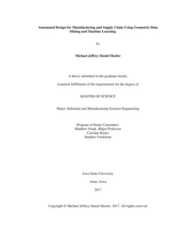
Results:Measured ValueLiquid Oxygen HolesTime PWeight22.31 s10 psi22.25 lbTime PWeight19.62 s10 psi18.31 lbTime PWeight26.54 s10 psi26.63 lbSince the fuel P was much higher than the LOX, a trim orifice was used on theLOX side of the injector. An increase of 60 psi was needed on the LOX side to correctthe difference between the LOX and the fuel. The Trim was machined out of aluminumalloy and the new P for the LOX was calculated at 147.4 psi and 154 psi for the fuel.The reason for the P being off from the calculated values had to do with themanufacturing of the injector. After performing the water test a very large P was found,initially. After investigating the problem, it was found that burrs left inside the injectorholes retarded the flow, creating a larger P. This was repaired by deburring the holesand retesting the injector.The other main losses came from a combination of the fittings, which connect thepropellant lines to the injector, and the dynamic head loss. The dynamic head lossoccurred when the flow of propellant entered the injector at 90º, creating a stagnationregion and slowing down the flow through the injector.4.2 Static Fire TestThe objective of the static fire test was to validate the design and verify the engineperformance. The chamber pressure and the amount of force produced by the enginewere recorded and compared to the predicted values.The static fire test was performed on April 28, 2002 at the Reaction ResearchSociety (RRS) Mojave Test Area (MTA) facility in the Mojave Desert using the staticfire test stand provided by Garvey Spacecraft Corporation and funded by The CaliforniaLaunch Vehicle Initiative (CALVEIN). The stand includes a steel structure, twopropellant tanks, one for alcohol and one for the LOX, and all the plumbing to supplypropellants to the engine. Commands to open and close the propellant valves were sentfrom a computer that was housed in a near by concrete bunker. This computer alsocollected data from three 500-lbf load cells, that attached the support stand to the engineto measure the thrust produced, and a pressure transducer on the side of the combustionchamber, which provided chamber pressure (the long ¼ in tube mounted to the side of thecombustion chamber can be seen in Figure 10). Figure 9 shows the engine on the teststand ready to be fired.
Figure 9-Aerospike Engine on VTS-2Figure 10The engine ignited successfully and began to create the expected flow pattern asis evident in Figure 10 taken 200 ms after ignition. However, right after that, the engineexploded. An investigation of the engine components and slow motion video leads to thebelief that the breakage of the spike was the initial point of failure. The pressure actingon the inner surface of the spike forced the spike out of the chamber, which closed off thethroat gap. This created a higher pressure in the chamber than in the manifold. The fuelmixture was forced into the injector manifold where it exploded destroying the rest of theengine.
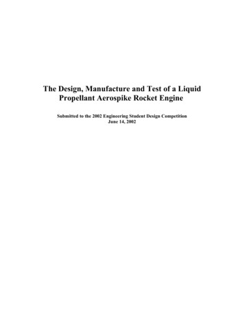
Figure 11The data collected was of limited value for two reasons. First, the sampling rateof the data collection was slow at only 5 samples per second, and second; the engineexploded 200 milliseconds after startup. Due to the low sample rate and the very shortburn time little data was actually collected. The data that was obtained is shown inFigure 10.Load Cell and Cham ber Pre ss rue Data14001200Load Cell 11000PcLoad Cell 2800Load Cell 36004002000405060708090100-200-400-600TimeFigure 12– Load cell data received during static fireFrom Figure 10 it is evident that things did not go as planned. The chamberpressure (Pc) experienced a small rise, about 150 psi, and then fell off. This is probablydue to the fact that the chamber had exploded and the pressure transducer was no longerattached nor was it working properly. The first load cell recorded a load of about 1261
lbs at the point of the explosion. Since it was rated to measure 500 lbs, the load cell wasprobably broken in the explosion and stayed at the point of maximum reading. The loadcell was taken apart after the testing and it was found that the strain gauge had actuallybroken in half. Since the wires were no longer connected, it experienced an infinite load,which kept it at the maximum reading. Load cell 2 experienced the same load at theexplosion. However, when this one broke it started to read a negative applied load. Thiscould be due to the fact that when the load cell broke the strain gauge was compressedand read less resistance resulting in the negative reading. The third load cell is interestingbecause it shows the most activity. It starts off reading the thrust that is initiallyproduced by the engine. It then becomes negative at the explosion. This is probably dueto the fact that the explosion created a tension load on this side of the plate resulting in atwisting moment about the center of the plate. After the pieces of the engine fall off ofthe test stand, the load cell returns to it no load value.Due to the short burn time and the low data sample rate, the data collected wasnot very useful. In future tests the data sample rate will be increased with betterequipment. This should allow for better data collection.5.0 ConclusionThe static fire test conducted at the MTA on April 28, 2002 validated most of thedesign of the aerospike engine. Although the spike nozzle failed structurally, Figure 13shows that the engine operated successfully, albeit for only 200 ms.Figure 13-Left Picture-at t .250, Right Picture – at t .500 (at 30 fps, these areconsecutive frames)Although the test resulted in the destruction of the hardware and in studentdisappointment, it also taught students and the rest of the team that the path to success istortuous and that one should not give up. A test resulting in broken hardware can teach alot more than paper studies, and emphasizes the balance that needs to be reached betweenthe two.
The team is already working on modifying the plug design and building animproved engine. Static fire test of the modified engine is scheduled to take place at theend of the summer. If the static fire test of the modified engine is successful, the enginewill be integrated into the Prospector-2 vehicle (which flew and was recovered back inFebruary) for the first powered flight of an aerospike engine in the history of rocketpropulsion development.5.1 The Lessons LearnedDuring the water flow testing it became apparent that deburring all of the injectorholes greatly decreases the pressure drop across the injector. Therefore, in the futuregreat care will be taken in the deburring of all injector holes in order to achieve thedesign pressure drop.It was found that design changes that influence dimensions should be welldocumented and traced back to all dependants. This should be done to avoid conflicts inpart sizes.It is apparent that more analysis should be done in order to qualify the materialsused to manufacture the components. The failure of the graphite spike may have beenavoided if more detailed analysis of the forces acting on it and the tensile strength of thematerial were analyzed.Looking at the data that was obtained from the static test, it is apparent that ahigher sample rate is required in order to achieve more fidelity in the data. This willallow better determination of the failure modes.5.2 Design ChangesCurrently the team is working on design of the second generation aerospikeengine taking into consideration the lessons learned from the previous engine. Onedesign consideration would be to incorporate a steel rod through the center of the spikeelement in order to strengthen it in tension.Due to the harsh environments of startup, a symmetrical ignition system is inconsideration for the next engine. This would help to eliminate some of theunsymmetrical forces that act on the spike during the ignition process.
References1. George P. Sutton, Oscar Biblarz Rocket Propulsion Elements, Seventh EditionJohn Wiley & Sons, Inc, New York, NY. 20012. David H. Huang,Dieter K. Huzel (Editor) Modern Engineering for Design ofLiquid-Propellant Rocket Engines American Institute of Aeronautics &Astronautics, Reston, VA 19923. Giamfranco Angelino Approximate Method for Plug Nozzle DesignAmerican Institute of Aeronautics and Astronautics, Reston, VA. 1964.4. Gabriel D. Roy Advances in Chemical Propulsion: Science to TechnologyCRC Press, Boca Raton, FL LLC 20015. Threshold. Spring 1992. The Boeing Co. 04 November zzledesign.jsp6. G.V.R Rao Spike Nozzle Contour for Optimum Thrust Pergamon Press Inc.New York, NY 1960.AcknowledgementsSpecial thanks to Tom Mueller, Brandy Irish, John Garvey, Eric Besnard, Mike Novratil,Paul Skaar and Mike Fritz
2200, a linear aerospike that was static fired several times. However, after more than four decades of research, no aerospike engine is known to have powered a rocket in flight. 1.4 How thrust is produced An important equation, derived from the conservation of momentum, helps to understand what influences the thrust of a rocket engine (eq. 1):