Transcription
Abdel-Malek, K. and Maropis, N., (1998), "Design-to-Manufacture Case Study: AutomaticDesign of Post-Fabrication Mechanisms for Tubular Components," SME Journal ofManufacturing Systems, Vol. 17, No. 3, pp. 183-195.A DESIGN-TO-MANUFACTURE CASE STUDY: AUTOMATICDESIGN OF POST-FABRICATION MECHANISMS FORTUBULAR COMPONENTSK. Abdel-Malek, Department of Mechanical Engineering and Center for ComputerAided Design, The University of Iowa, Iowa City, IAN. Maropis, UTI Corporation, Collegeville, PAAbstractAn automated design-to-manufacture system and the description of itsimplementation are outlined. The system is described in the context of rapidprototyping of a mechanism for the post-fabrication of miniature metal tubularcomponents.Post-fabrication operations considered include dimpling, bending,slotting, lancing, punching, corsetting, and notching.The system has beendemonstrated to reduce design-to-manufacturing cycle time by many orders ofmagnitude. The method outlined encompasses the integration of rule-based expertisewith theoretical considerations underlying the manufacturing process. Using anartificial intelligence language, this module is then linked to a computer-aided designsystem to automatically generate detailed drawings of the mechanism. The systememphasizes the automatic design of the assembly and generation of blue prints and NCcode for appropriate mechanical parts. To determine whether a component can bemade using current company technology, an advise-on-manufacturability module wasdeveloped. This paper describes the methodology used in developing this system aswell as the difficulties encountered during the development.Keywords: Rapid Prototyping, Design-to-Manufacturing, Metal Working, MachineDesign, and metal fabrication.IntroductionThe importance of software development in the manufacturing industry can be seen by a recentemphasis of CAD software developers on the production of high-level systems aimed at thecomplete automation of design processes. A recent trend by manufacturing companies has beentheir use of large-scale parametric software suitable for integration into existing design methods.Parametric-driven technology and geometric modelers have reportedly achieved a significantlyhigher productivity level.1 Rule-based design has affected design-time, cost, and performance.More recently, a new generation of systems such as seamless design-to-manufacture (SDTM)1
have appeared2 that integrate rule-based systems with parametric based technology. Because thistype of system is a rule-based structure, it has the ability to automatically generate part geometry,process geometry, and various geometric models needed for analysis.In some cases, these systems also include an automatic rule-driven numerically-controlled(NC) code generator, which translates CAD data into suitable NC code. A similar system that istargeted toward integrating an end-product directly from the designer’s CAD system or solidmodeler was presented by Mayer et al.3. This system is able to generate a process plan, a toolpath, and NC code. Other systems have appeared in Chen and Voleker’s work4 where themanufacturing engineer needs only to specify the process plan. The complete part program couldbe derived from the plan specified. A design-to-manufacture system for the roll-forming industrycalled CARDAM was reported by Nallapati and Somasundaram.5 The system integrates CADand CAM facilities to design the roll form, roll profile, as well as editing and NC processing ofroll profiles. In the metal working industry, most approaches to achieve a design-to-manufacturehave been based upon multiple set-ups of a single part.6-9 Modeling methods are described byChang and Wysk10 and Requicha and Vanderbrande11. Modeling by features were presented byShah12 and edge-faced graphs were presented by De Floriani.13Every manufacturing engineer carries a personal knowledge-base grounded upon a life-timeexperience. This experience, is mostly based upon rules-of-thumb that are gathered through trialand error. These rules-of-thumb, although often descriptive, are used by programmers to developexpert systems to determine the manufacturability of similar products or families of parts.14Currently, many far-thinking manufacturers are using expert-system shells to establish setups, todetermine sequence of machining operations, to set machine parameters, to select approporiatetooling, and to generate tool paths and NC code. Artificial intelligence-based systems have beentried in the manufacturing industry.15 Reducing lead times in the manufacturing environment hasbeen the subject of many recent studies. Olsen16, for example, addresses the necessity of suchsystems and their impact on today’s competetive market, while an economic model that addressesthese issues was introduced by Ulrich et al.17This paper discusses the integration of many modules including a rule-based system, atheoretical consideration module, a CAD environment, and an artificial intelligence language(Lisp) to perform the design function. The ultimate goal is to reduce lead times associated withthe design of a specialized post-fabrication mechanism that include dimpling, bending, slotting,lancing, punching, corsetting, and notching.This system will design the layout of the mechanism, generate the detailed drawings of parts,and will provide advice on manufacturability of the end-product. The choice of commercialsoftware, programming language, or expert system shell is irrelevant to the concept introducedhere and will not be given emphasis.Given a complete description of an end-product, it is necessary to develop a system thatprovides a user with the following functions.(1) Advise-on-manufacturability module. This module contains two types of rules: (a) rules ofthumb and (b) theoretical considerations. This module will inform the user whether the partcan be made (i.e., if it is within current company capabilities). If the part is not within currentcapabilities, this module will check whether the part can be made according to the classicaltheory of metal deformation. If this module determines that the part cannot be made, a searchtechnique is used to recommend an alternate design.2
(2) Design-engine module. This aspect of the system is in two parts: (a) standard componentsthat can be stored on the shelf for immediate assembly when needed, and (b) components thatrequire new design.(3) NC code-generation module. This module implements an algorithm for the generation of NCcode for different machining processes.(4) A user-interface module. An interface that provides the user with the ability to enter the endproduct description and to intervene during the design process, as well as after the detaileddesign is generated.What follows is a more detailed discussion of the implementation in the context of postfabrication. Linking of the different modules and automatic generation of blue prints issubsequently discussed.Advise-on-ManufacturabilityTo program a computer with the ability to determine whether a part can be made is a verycomplicated task. The difficulty stems from obtaining such knowledge in terms of expert rulesthat can be programmed. It has been shown to be of extreme difficulty to take an experiencedtool-maker or manufacturing expert and ask them to write everything they know about theprocess. Methods for interrogating experts and extracting expert rules are well documented18Having achieved this stage, it is necessary to translate these rules into computer code. Allconceivable situations have to be captured. Furthermore, if many experts exist and they allachieve the same end-product, their process may be significantly different and theirmanufacturability criteria may also differ. Thus, the task of obtaining consensus rules thateveryone may agree with, may also prove difficult. These problems and many others have beenaddressed in the field of expert systems.18,19 During the development of expert systems,knowledge engineers obtain the information from experts and prototype a computer system thatcontains the rules. Knowledge engineers spend a great amount of time with the experts and areprimarily concerned with the thought process.For the purpose of developing a relatively small system such as the one discussed in thispaper, it is our recommendation to use a scheme opposite to the one discussed above. Instead oftraining a knowledge engineer to extend his expertise to manufacturing, we recommend training amanufacturing expert (tool-maker or manufacturing engineer) to the role of a knowledgeengineer. The motivation for this stems from the fact that other experts will feel less reluctant tovolunteer their expertise, which is a common problem in expert system development. In addition,experts will feel that they still do retain job security since the development is among themselves.Assigning one or more experts to the task of learning a new technology develops a sense ofownership tied to the company’s future success.The two cases were tested at two divisions of a corporation. In one case, a knowledgeengineer with significant expertise at gathering knowledge and computer programming wasassigned the task of developing a rule-based system for a deep-drawing process at the company’sConnecticut eyelet division. In this process, sheet metal is transformed into a cup-shaped part. Inanother division in Pennsylvania, a tool-and-die maker with a life-time of experience in themanufacturing of miniature metal tubular components was assigned the task of developing rulesand a computer program for the post-fabrication of tubular components. This expert had no priorknowledge in expert system development.3
The results were significantly different. The manufacturing expert had collected rules, learnedbasic programming, expert system shells, and developed a full-scale system in 16 months. Theknowledge engineer took approximately the same time to interact with the experts to learn theprocess. It took the knowledge engineer an additional number of months to implement it into acomputer. This experience has showed that for at least this case, it is much more efficient for amanufacturing expert to learn programming rather than for a knowledge engineer to learn the insand outs of a specific process.System LimitsOnce the rules are obtained, a module that advises on manufacturability was developed. Thismodule works interactively with the user to define the end product and to respond with a decisionon whether this specific part can be made. This decision is based primarily upon expert rules andto a second order upon theoretical considerations. It has been our experience that expert rules areusually more conservative than those allowed by the classical theories of metal deformation. Forexample, the shearing operation that occurs in slotting, punching, notching, and lancing of tubularcomponents can be defined as a region of capability using expert rules as depicted in Figure (2).For a certain alloy, a specified punch size, an outside diameter, and a wall thickness, the capabilitylimits are defined. Although this graph does not take into consideration many factors, it is theoutcome of the rules provided by the manufacturing experts. Thus, it does represent a viableindication whether the part can be made.Alloy #1Punch size AOutsidediameterExpertrule-basedcapabilityWall thicknessFigure 2Window of Capability Gathered by ExpertsFigure (3) depicts a number of graphed results using theoretical analysis.20 Figure (3a)depicts the relation between shearing resistance and wall thickness and Figure (3b) depicts therange of the shearing resistance versus tensile strength.4
Alloy #1(Shearingresistance)(tensilestrength)Alloy #1Shearingresistance(psi)Wall thickness (in)Tensile strength (psi)(a)(b)Figure 3(a) Shearing Resistance as a Function of Sheet Thickness (b) Ratio of Shearing Resistance to TensileStrength as a Function of Tensile StrengthFigure (3c) indicates that shearing resistance becomes a constant at larger sizes. A moretheoretical consideration is depicted in Figure (3d) which indicates the relation between the ratioof shearing energy to shearing area versus relative aringareaAlloy #1Alloy #1Relative clearancePunch size (in)(d)(c)Figure 3(c) Effect of Punch Size on shearing Resistance (d) Ratio of Shearing Energy to Shearing Area as a Functionof Relative ClearanceThese curves were approximated into a single window of capability which takes into effect thematerial type, punch size, and part geometry. The resulting window of capability is plotted on thesame graph of Figure (2) and shown in Figure (4). For the case of shearing of tubularcomponents, it is evident that expert rules are more conservative than using the classical theory ofmetal deformation. Thus, to determine whether a part can be made, this module will firstinvestigate the expert rules. If the part is not within current capability, it will advise the user thatthe part can potentially be made if it is within the theoretical capability window.5
Alloy #1Punch size calcapabilityWall thicknessFigure 4Capability of Both the Rule-Based System and the Classical Theory of Metal DeformationFurther theoretical aspects were considered, such as the computed size of the slugs inside thetubular part, the force requirement of the press, and the bending strength of the mandrel (die) thatwill withstand the punching force. Figure (5a) depicts a schematic of the punches and theresulting slugs. The punches, mandrel, and supporting block will be designed for the fouroperations (slotting, punching, notching, and lancing). Figure (5b) depicts the method of slugejection (if needed) through an air nozzle. Note that the size of the mandrel inside the tubular partlimits the force required to perform the shearing and the maximum allowable size of the resultingslugs. All of the above rules are entered into the system in mathematical form.support blocktubular parttubular partairnozzleFpunchpunchair outFtubeslugsmandrelslugpassage(a)(b)Figure 5(a) Tube, Slug and Punch (b) Slug Ejection MechanismCase Study: Tube BendingOne of the most important aspects of bending of tubular components is necking. Theoreticalcriteria set forth for the bending of sheet metals do not adequately represent the deformations inbending of tubular components. Localized necking occurs at an earlier stage than that predictedtheoretically.20 In this case, expert rules were used again to determine the manufacturability of apart. For example, for 304 stainless steel, and for a wall thickness 0.003 w 0.008 , and anoutside diameter to wall ratio 10 Do / w 15 , the bend radius R depicted in Figure (6c) issubjected to the following rule.R 2( Do )where the minimum length for holding the tubular component (A) on each side should beA 16. Do to eliminate secondary trimming.166
wσyDoy1βrdααθηyδRδfAw(b)(a)(c)Figure 6(a) Cross section of a tube subjected to pure bending (b) Elastic-plastic distribution (c) nomenclatureWhen designing tooling for tube bending, it is necessary to know in advance the springbackratio of the bend radius. Once this ratio is determined, it is passed on to a routine thatautomatically generates the tooling. Although a complete solution to the problem of calculating aspringback is unknown, the following is a theoretical analysis that was implemented. From theelementary theory of strength of materials, the moment induced on a cross section is(1)M σydAIwhere σ is the stress, y is the distance from the neutral axis, and dA is an element of area. As Mincreases, the stress distribution in the annulus remains linear until the stress equals the yield stressσ y (Figure 6b). The force F, applied at the centroid of region 1 (above η ) isF σ y r (2 β )t(2)where σ y is the yield strength, β is defined in Figure (6a), and t is the thickness of the tube. Asthe radius of curvature of the tube decreases, the thickness of the plastic region increases, and theelastic boundary approaches the neutral axis. The moment acting on region 1 isM1 2σ y rt ( βy1 ) 2σ y rtf1 (η )(3)where the function f 1 (η) is defined as f 1 (η) βy1 . The angle β can be written as β and the angle θ isθ sin 1The moment acting on region 2 (below η ) isM2 Iπ θθydf Iπ θθ2 η r(4)σy(r sin α ) 2 trdαηThus the total moment MIσy 3 θ 2M M1 M 2 2σ y rtf 1 (η ) 2r t sin αdαη0Evaluating the integral yieldsσ y 3 sin 2θ θ2σ y rtf 1 (η ) 2rt η42where 7π θ ,2(5)(6)(7)
f 1 (η) βy1 π θ 2r cosθ r cosθ R 2 1π 2θ 6R(8)EIIwhere the centroid of the section y1 , used in equation 8, isy1 ydA(10)dAand derived as follows. For an element of area dA, each part of equation 10 can be integrated toyieldI II IdA π θrtdα rt (π 2θ )(11)r 2t sin αdα 2r 2 t cosθ(12)θydA π θθThe location of the centroid of region 1 is determined as follows2r cosθy1 (13)(π θ )For a radius of curvature R from the neutral axis of the tube, the elastic-plastic condition isσy η(14) ERThe change in the radius of curvature due to springback is RE , thus the moment M isEr 3tπ(15)M REFor a tube that has undergone a deflection δ , and when unloading occurs, the elastic springbackis δ E , thus the final deflection δ f is computed asδ f δ δ E(16)The springback λ is thus calculated from the following equationRRλ 1 (17)RFRESubstituting equation 14 into equation 7 and equating it to equation 15 yieldsσ y 3 sin 2θ θEr 3tπ(18)2σ y rtf1 (η ) 2rt η42REThus the springback is computed numerically by substituting different values for R / RE .Knowledge of the springback allows the automatic design of a bending mechanism. For differentalloys, Figure (7) shows plots of the springback ratio versus the radius of curvature to diameterratio. 8
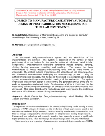
1.0Springbackratioδf/δR/Do100Figure 7Springback ratio versus radius of curvature to diameter ratioCapabilitiesDesign of part, process, and performing analysis are iterative tasks, each composed of twoprimary phases: (1) component design and (2) detailed design. The conceptual design of thegeneral mechanism needed to manufacture this family of parts has been enhanced throughout theyears by the experts. This section introduces the capabilities of the system in view of anautomatic blue print generation, automatic NC-code generation, and user interface modules.Attempts have been made in the past to standardize the components that go into the design ofmechanism with different degrees of success. The design process, however, still relies uponhuman expertise. A multiple of designs may exist for a single mechanism.An example of a design-to-manufacture system that has been reported for a family of parts isthe Seamless Design-to-Manufacture (SDTM) system presented by Hazony and Zeidner.2 Theauthors report that this system has a fully-automated geometry generator which convertsparametric part and process designs to the corresponding detailed part and process geometry.Numerically Controlled (NC) code is also generated. The part and process design in this system,however, are carried out interactively with the user and not automatically generated.In the case study presented here, the conceptual design of the mechanism has beenprogrammed into the system and is carried out by the system. In order to teach the computer adesign method, it is necessary to set up guidelines for the design process. Eleven manufacturingexperts were consulted to obtain these guidelines. In the process, several components werestandardized so that no redesign of these components is needed. In fact, these standardizedcomponents were fabricated and placed on the shelf for immediate assembly and will be referredto as off-shelf components.Design of the mechanism is governed by the part geometry, part material, slug shape, slugdimensions, and required tolerances and surface finish. Force requirements for achieving theremoval of slugs are computed.21 The design is altered accordingly. For example, a relativelylarge force may require the addition of a support block to the design. A support block is a massthat surrounds the part and allows the punches to pass through. This block provides a rigidsupport for the post-fabrication operations. The block will also constrain the punches uponcontact with the part reducing edge draw-ins. In the case of one punch, a relatively large bendingmoment is induced which may cause dents and deformations in the part. To eliminate suchproblems, it is often obligatory to design a suitable mandrel that is located inside the tube. Inaddition, tolerances mandated by the end-product may require a special design of the mandrel.9
Penetration depths of cracks, smoothness, and burr size, as depicted in Figure (9), are factors thatdetermine the size of the mandrel and its rigidity. These aspects may contradict, however, spacerequirements needed for the ejection of slugs. An optimization method was used to determine asuitable mandrel size.22 The constraints used are the space requirements, tolerances, materialdeformation, and mandrel rigidity. The cost function to be minimized is the mandrel’s insidediameter.Edge draw-inSmooth shearFracturedBurrDepth of crack penetrationFigure 9Form Errors in ShearingTo illustrate the above discussion, consider the design of a double-parallel punchingmechanism depicted in Figure (10) (only one punch assembly is shown). Standardizedcomponents that were fabricated include the slug ejector mechanism, the hold/eject mechanism,and slide housings. The remainder of the parts are either parametrically altered or designedaccording to the required product.stripperplate andsleevepunch holderslidehousing(top)camclamp blockhold/ejectmechanismmandrelblockmandrelair supportblockpunchejectorpinslide housing(bottom)slide housing (side)Figure 10A Double-Parallel Punching Mechanism10
Automatic Blue-Print GenerationIn order to program a computer with the ability to generate detailed drawings, it is necessaryto identify a tool that performs both analysis and control. It is emphsized here that the automaticgeneration of blue prints means the the actual drawing of a part having various dimensions everytime (i.e., depends on its functionality).Therefore, analysis is necessary in order to performthe requested calculations prior to design. Control is also necessary in order to manipulate thegeneration of drawings. Computer languages such as C, Fortran, Pascal, and Basic are notsuitable for this type of application. Artificial intelligence languages are most suited to performlogic as well as command routines in other software packages. For example, an object orientedframework for the integration of design and manufacturing in an automated system was reportedby Mo et al.23 CAD companies have used these languages to manipulate graphical entities on thescreen. CAD systems use these languages to provide a user with the capability of writingspecialized functions. Examples of these artificial intelligence languages are AutoLisp formanipulating AutoCAD graphical entities; CAD-L for manipulating CADKEY graphical entities;and Pro-Develop for manipulating Pro-Engineer drawings.For this application, AutoLisp is used to automatically generate detailed drawings. Forexample, consider the automatic design of a support block for the sharing operation of a tubularcomponent. Depending on the various inside and outside diameters, length, material properties,load and tolerance requirements, a support block is automatically designed. The algorithminitiates the graphical environment (AutoCAD) by setting the pertinent parameters such as limits,zooming, and layers. For each view needed to represent this part, the program defines thecoordinates of a number of key points. The program then proceeds to draw graphical entities onthe screen. Three-dimensional features are then inserted. Finally, dimensions and drawing notesare added accordingly. Note that parametric CAD software can only change the dimensions of apart. Parametric systems do not have the capability to perform logic, thus do not have thecapability to aid in design. The resulting detailed drawing, automatically generated by the Autolispcode, is shown in Figure (11).11
Figure 11The Support Block Generated AutomaticallyRules that govern the physical dimensions of the automatically generated part are written inAutolisp. These rules mathematically mandate the design crieteria for the part. For example, rule13 calculates slug clearances and determines the allowable space required for the punch. It alsouses a 1.2 factor of safety to allow for space clearance based on expert advice. Rule 21 computesestimated deflections by the tube, and determines whether a support block is needed. If it isdeemed necessary to design a support block, another set of rules are called upon. Rule 32computes the force needed to perform the shearing operation for a specific material of knowndimensions. Thus the forces and moments sustained by the tooling need to be estimated. Thebending moment for a tubular component can be writtten asIε x ,oM Do R2nσ x (ε x )ε x dε x(19)ε x ε x ,iLet ε ε x , then equation 19 can be written as Rm Dno2Iε x ,oσ (ε )εdε(20)ε x ε x ,iTo evaluate the unit moment, the stress-strain curve σ (ε ) is evaluated where the assumption ismade that the curves are equal in tension and compression such that ε x ,o ε x ,i . Unit momentcurves are determined for many materials and are available in the literature. The bending momentis then calculated as3M mDo(21)In order to expedite the assembly and debugging process of the mechanim, the user of thissystem is prompted to select the detailed drawings needed. A menu indicating all possible parts12
needed for the assembly of this mechanism appears on the screen and the user is prompted toselect those that are needed. Since it is possible that previously made parts can be recycled in anew mechanism, regeneration of that part is not necessary. The detailed drawings generated bythe system will appear on one screen. To determine whether a part is recyclable is still a manualfunction which will be automated. Figure (12) is a snapshot of the screen with a number ofdetailed drawings displayed. The user then has the provision to edit the details of any drawing.Figure 12A Snapshot of Detailed Drawings Generated AutomaticallyIt is emphasized that the above set of detailed drawings (Figure 12) represent the total set of blueprint drwaings necessary to manufacture and assemble a mechanism for the intended operation.It is also noted that although these drwaings appear in miniature in this manuscript, they are fullyaccessible to the user through viewing capabilities of the CAD system being used. The intentionhere is to emphasize the automatic ability of the module and not the details of the drawings.Automatic NC-code GenerationThis module contains a generative numerical control method, where numerically controlled partgeneration programs are automatically created from CAD drawings. Using an expert system thatreflects the manufacturers preferred practices, this module creates a machining program byassembling all individual operations.24 The specific system that is used in this module can befound in Ragenbass and Reissner25 for various stamping operations. Those for generating lasercutting NC code from CAD data can be found in Jackson and Mittal.2613
User Interface Using an Expert System ShellUsers of this system are machinists and manufacturing experts who are involved in the day-today activities of this operation. These users have little or no training in computers. It wasnecessary to develop a computer interface that is simple to use and yet powerfull enough tointegrate the various modules of this system. This interface contains rules that constitute theinference engine of this design-to-manufacturing system.Symbologic Adept was selected to provide both a rule-based system and a graphicalinterface. Although any expert system shell could have been selected to perform the integrationfunction, this commercial code was found adequate for integrating this system in a PC-basedwindows environment combining AutoCAD, AutoLisp, and NC-code generation code using Clanguage. Rules in Symbologic Adept are programmed in both logic and mathematical forms.The program has also the ability of communicating with other software packages through theDynamic Language Library scheme in the Windows environment. Specifically, this software waslinked to the AutoLisp libraries written for the automatic generation of detailed drawings. Beforeproceeding with demonstrating how Symbologic was used in linking the different modulestogether, it is necessary to identify the relevant symbols used in developing the software. Figure(13) depicts three different types of ‘nodes’ that constitute the building blocks of this software. Anode represents various types of commands, conditionals, interfaces, and data.InputA display node is where interface screens may be built and userinput may be requestedA calculation node is where logic and mathematical functions may beevaluated and where communication with other programs is carried outA goal node is where the program branches to another procedureA custom node is where criptic language (similar to C-languagelanguage) can be inserted.OutputFigure 13Three Types of Nodes Used by Symbologic AdeptConnecting these nodes to each other mandates the order of execution of the program. Eachnode has a logical value manifested by the choice of the line connecting the rectangular block atthe top and bottom of each node (c.f. Symobologic Adept manuals for more details) . Theprogram proceeds from one node to the other across several procedures. If another software iscalled upon to perform a function, the software is executed and upon successful completion, theprogram returns to the calling node
A design-to-manufacture system for the roll-forming industry called CARDAM was reported by Nallapati and Somasundaram.5 The system integrates CAD and CAM facilities to design the roll form, roll profile, as well as editing and NC processing of roll profiles. In the metal working industry, most approaches to achieve a design-to-manufacture