Transcription
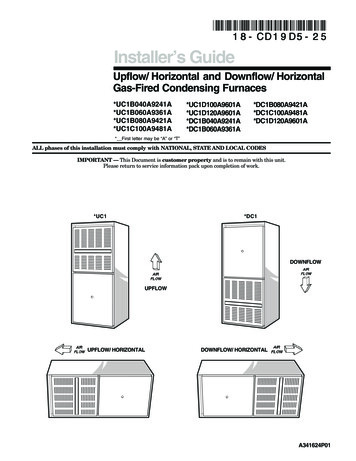
E7 Series Electric FurnaceINSTALLATION INSTRUCTIONSDownflow & Upflow ModelsE7EM MULTI-POISEE7EU UPFLOWWARNINGELECTRICAL SHOCK, FIRE OREXPLOSION HAZARDFailure to follow safety warnings exactly couldresult in serious injury or property damage.Improper servicing could result in dangerousoperation, serious injury, death or propertydamage. Before servicing, disconnect all electricalpower to furnace. When servicing controls, label all wires priorto disconnecting. Reconnect wires correctly. Verify proper operation after servicing.DO NOT DESTROY. PLEASE READ CAREFULLY &KEEP IN A SAFE PLACE FOR FUTURE REFERENCE.E7ED DOWNFLOWATTENTION INSTALLERS:It is your responsibility to know this product better than your customer.This includes being able to install the product according to strict safetyguidelines and instructing the customer on how to operate and maintainthe equipment for the life of the product. Safety should always be thedeciding factor when installing this product and using common senseplays an important role as well. Pay attention to all safety warnings andany other special notes highlighted in the manual. Improper installationof the furnace or failure to follow safety warnings could result in seriousinjury, death, or property damage.These instructions are primarily intended to assist qualified individualsexperienced in the proper installation of this appliance. Some localcodes require licensed installation/service personnel for this type ofequipment. Please read all instructions carefully before starting theinstallation. Return these instructions to the customer’s package forfuture reference.
TABLE OF CONTENTSIMPORTANT SAFETY INFORMATION. 3REQUIREMENTS & CODES. 3Minimum Installation Clearances.3Minimum Unobstructed Airflow.3Clearances to Combustible Materials.3CIRCULATING AIR REQUIREMENTS. 4Return Air Connections.4Supply Air Connections.4Filtering Methods - Downflow Furnaces.4Non-Ducted Return Air.4Without A/C or H/P uncased coil.4With A/C or H/P uncased coil.4With optional coil housing.4Ducted Return Air.4Filtering Methods - Upflow Furnaces.4Non-Ducted Return Air.4Without optional upflow stand.4With optional upflow stand.4Ducted Return Air.4Optional Equipment.5Optional Automatic Furnace Damper.5Duct Connectors for Downflow Systems.5FURNACE INSTALLATION. 5General Information.5Before You Install this Furnace.5Locating the Unit.5Locating & Cutting Floor Openings.5Standard Duct Connector Installation.6Narrow Duct Connectors.7Round Duct Connector Installation.7Alcove Installation.7Closet Installation.8Upflow Furnaces.8Over-the-Floor Return Air System (Non-Ducted).8Through-the-Floor Return Air System (Ducted).92ELECTRICAL WIRING. 10Line Voltage Wiring.10Connecting Supply Service Wires.10Grounding.11Thermostat / Low Voltage Connections.11Humidifier.11Dehumidification Options.11Electronic Air Cleaner (EAC).11Changing Blower Speed.11Installing Control Circuit Wiring.11START-UP & ADJUSTMENTS. 11Pre-Start Check List.11Start-up Procedures.11FIGURES & TABLES. 12Figure 16. E7 Furnace Components.12Figure 17. E7EM Physical Dimensions.13Figure 18. E7EU & E7ED Physical Dimensions.13Figure 19. E7 Furnace Upflow Stand Dimensions.14Airflow Data.15Table 4. E7 Airflow Data.15Table 5. Maximum Allowable Heat Settings.15Electrical Data & Diagrams.16Figure 20. E7EB Thermostat Connection.16Table 6. Unit Specifications.16Table 7. E7 Electrical Specifications.17Figure 21. E7 Motor Control Board.17Figure 22. E7EB-010H Models.18Figure 23. E7EB-012H Models.19Figure 24. E7EB-015H Models.20Figure 25. E7EB-017H Models.21Figure 26. E7EB-020H & E7EB-023H Models.22Table 8. Control Board Operation.23INSTALLATION CHECKLIST. 24
IMPORTANT SAFETY INFORMATIONINSTALLER: Please read all instructions before servicingthis equipment. Pay attention to all safety warnings andany other special notes highlighted in the manual. Safetymarkings are used frequently throughout this manual todesignate a degree or level of seriousness and should notbe ignored. WARNING indicates a potentially hazardoussituation that if not avoided, could result in personal injuryor death. CAUTION indicates a potentially hazardoussituation that if not avoided, may result in minor or moderateinjury or property damage.REQUIREMENTS & CODESWARNING:This unit must be installed in accordancewith instructions outlined in this manualduring the installation, service, and operationof this unit. Unqualified individuals shouldnot attempt to interpret these instructions orinstall this equipment. Failure to follow safetyrecommendations could result in possibledamage to the equipment, serious personalinjury or death. The installer must comply with all local codes andregulations which govern the installation of this typeof equipment. Local codes and regulations takeprecedence over any recommendations containedin these instructions. Consult local building codesand the National Electrical Code (NEC) for specialinstallation requirements. All electrical wiring must be completed in accordancewith local, state and national codes and regulationsand with the National Electric Code (ANSI/NFPA70) or in Canada the Canadian Electric Code (CSAZ240.6.1, & Z240.9.1). Design and construction of the home duct system,must be in accordance with: HUD Manufactured HomeConstruction & Safety Standard (Title 24, Part 3280)and American National Standards (ANSI) A119.11,C1-NFPA 7. Plenums and air ducts must be installed in accordancewith the Standard for the Installation of Air Conditioningand Ventilating Systems (NFPA No. 90A) or theStandard for the Installation of Warm Air Heating andAir Conditioning Systems (NFPA No. 90B). Follow all precautions in the literature, on tags, andon labels provided with the equipment. Read andthoroughly understand the instructions provided withthe equipment prior to performing the installation andoperational checkout of the equipment.Minimum Installation Clearances Access for positioning and servicing the unit must beconsidered when locating unit. The need to provideclearance for access to panels or doors may requireclearance distances over and above the requirements.For alcove installations allow 24 (61 cm) inchesminimum clearance from the front of the unit forCLOSETALCOVEFront **ALL MODELS6"24"Back0"0"Sides*0"0"Top0"0"Top & Sides of Duct0"0"Bottom of Duct0"0"*For upflow application using upflow stand, 3” minimum per side.**Service ClearanceTable 1. Minimum Clearance Requirementsfuture servicing. Closet installations require 6inches minimum. This appliance must be installed in accordance withclearances listed in Table 1. The furnace must beinstalled with ample clearance for easy access to theair filter, blower assembly, burner assembly, controls,and vent connections. Locate and install this unit in position as specifiedon page 5. This unit is designed only for Indoorinstallations and should be located with considerationof minimizing the length of the supply and returnducts. See Table 4 (page 15), Table 5 (page 15), orthe rating plate for circulating airflow data.Minimum Unobstructed Airflow Sufficient clearance for unobstructed airflow must bemaintained in order to achieve rated performance. Airreturn to the furnace must have the minimum requiredtotal free area:— 200 in2 (1290 cm2 ) for furnace only. May alsoinclude return air grille and frame assembly P/N902989 or wall mount grille P/N 902999).— 235 in2 (1516 cm2 ) with 4 ton or smaller A.C. orH.P. installed.— 250 in2. (1613 cm2 ) with 4 ton or smaller A.C. orH.P. installed & 1” special clearance.— 275 in2 (1775 cm2 ) with up to 5 ton A.C. or H.P.installed. If using louvered doors, the total free area must becalculated. Louvered doors installed at the factory areabout 70% free area. If using a third party louvereddoor manufacturer, check their technical specificationsto determine the free area. For closet installations with less than 6” front clearance,but not less than 1”, a louvered door must be usedhaving a minimum 250 sq in2 (1,613 cm2) free areaopening directly in line with openings in the furnacedoorClearances to Combustible Materials This furnace is Design Certified in the U.S. and Canadaby ETL for the minimum clearances to combustiblematerials. NOTE: The furnace is listed for installationon combustible or non-combustible flooring. To obtainspecific clearance information, refer to the furnacerating plate, located inside of the furnace cabinet. 0” from all surfaces of furnace cabinet, ducts, optionalcoil housing and plenum connector. No separatesubbase required for installations on combustibleflooring.3
CIRCULATING AIR REQUIREMENTSWARNING:All return ducts must be secured to the furnacewith sheet metal screws. All return ducts mustbe adequately sealed.When return air is providedthrough the bottom of the unit, the joint betweenthe furnace and the return air plenum must beair tight.Return air and circulating air ducts must not beconnected to any other heat producing devicesuch as a fireplace insert, stove, etc. This mayresult in fire, explosion, carbon monoxidepoisoning, personal injury, or property damage.Return Air ConnectionsAir return to the furnace must have a minimum free areaopening that meets the minimum installation clearancesfound on page 5. A return air grille for closet or alcoveinstallations is available. Acceptable installations withreturn air entering through an opening in the floor, ceilingof a closet, or alcove installation, must meet all of thefollowing requirements: The return air opening, regardless of its location, mustnot be smaller than size specified on unit data label. Iflocated in the floor, the opening must be provided witha means of preventing its inadvertent closure by flatobject(s) placed over the opening. A return air grille must be used on the furnace wheninstalled in a closet or alcove:Upflow Alcove installations– E7EM Models: Use a coil box with a solid door andan upflow stand (Figure 1 (page 5)). Part numberscan be found in the Technical SpecificationsLiterature.– E7EU Models: Use upflow stand.Closet installations:– All E7 Models: A louvered door must be added inthe closet door or above it for adequate air flow.Downflow alcove installations:– E7EM Models: A grille may be attached to the topof the furnace and all paneling and trim flushedto it. This installation provides an access door forfuture installation of air conditioning or heat pumpcoils on top of the furnace.– E7ED models are for non-ducted return.– E7EU Models can be used for ducted return. Materials located in return air duct system must havea flame-spread classification of 200 or less. Noncombustible pans having 1” upturned flangesmust be located beneath openings in a floor-returnduct system.Supply Air Connections Supply duct system must be designed for proper airdistribution. Static pressure measured externally tofurnace shall not exceed static pressure rating listedon furnace nameplate.4 Duct system must be designed so that no supplyregisters are located in duct system directly below thefurnace.Filtering Methods - Downflow FurnacesNon-Ducted Return AirFor unducted return air systems, either the optional grilleand frame assembly or the optional wall mount grille isrecommended. E7ED Models: Make sure there is an 18”x20” filter inthe top filter rack and an 18”x30” filter in the front filterrack.Without A/C or H/P uncased coil Use the filter supplied with the furnace. Make surethe filter is installed mat side down between the filterretainer and furnace top.With A/C or H/P uncased coil Use the optional coil filters; the filter supplied with thefurnace is not used; REMOVE AND DISCARD THISFILTER.With optional coil housing See coil cabinet instructions for specific filteringmethods.Ducted Return AirFor ducted return air systems with air conditioners orheat pumps, either providing an access panel in the ductor using the optional coil cabinet is recommended. Theduct system must be properly sized to account for anyadditional external static pressure produced from thechosen filtering method.NOTE: Install a filter with a minimum unrestricted mediumarea that meets the application requirements of the furnacein the duct above the coil that is accessible for monthlycleaning or replacement by homeowner.Filtering Methods - Upflow FurnacesNon-Ducted Return AirFurnaces may be installed with unducted or ducted returnair. For unducted systems it is recommended to use anupflow stand for optimal performance.Without optional upflow stand Install a filter with a minimum unrestricted medium areaof 324 in2 below the coil cabinet/furnace assembly thatis accessible for monthly cleaning or replacement bythe homeowner.With optional upflow stand Stand (Figure 1) will use filters provided with the unit.Remove any filters in the furnace and follow properinstallation. See instructions supplied with the upflowstand for additional details.Ducted Return AirFor ducted systems with air conditioners or heat pumps,the following optional equipment is recommended: coilcabinet and upflow duct connector.
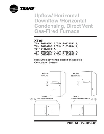
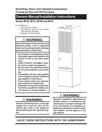
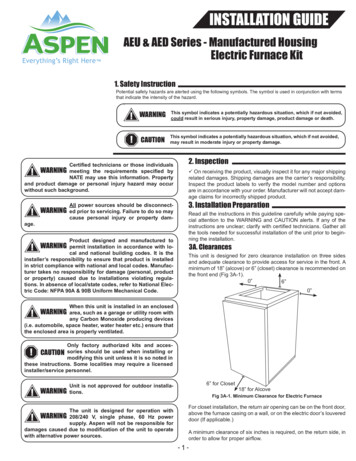
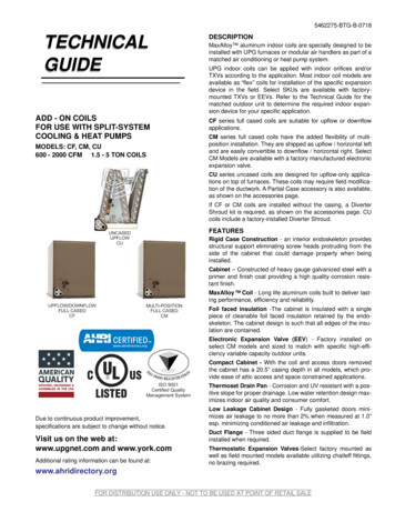
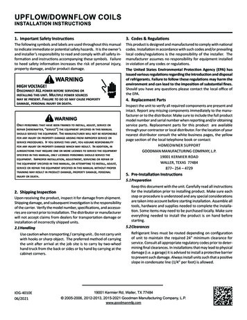
24 3/4” (628 mm)20”(508 mm)20” (508 mm)Upflow StandFigure 1. Optional Upflow Stand Install a filter with a minimum unrestricted mediumarea that meets the application requirements of thefurnace below the coil cabinet/furnace assembly thatis accessible for monthly cleaning or replacement bythe homeownerOptional EquipmentNOTE: Refer to the instructions supplied with any additionalaccessories for further installation details.Optional Automatic Furnace DamperFurnace may be equipped with the optional automaticdamper when a packaged air conditioner is installed andconnected to the warm air duct system. This damper (notrequired) prevents cooled air from discharging throughthe furnace cabinet, causing excessive cooling of theimmediate area. Refer to the instructions supplied withthe damper for details.Duct Connectors for Downflow SystemsDuct connectors are recommended for heated airdistribution in under-the-floor duct systems. With thissystem, furnaces may be installed on combustible flooringwithout a separate sub-base. The furnace rear mountingplate (Figure 5 (page 7)) supplied with the duct connectorsis recommended for use with this type of installation.FURNACE INSTALLATIONNOTE: Since all installations are different, the sequence ofthese steps may differ from the actual installation. Theseinstallation procedures are suggested for typical furnaceinstallations. Only qualified HVAC technicians shouldinstall this furnace.General InformationThis electric furnace is designed only for indoorinstallations. Units are approved for single/multistoryresidential or mobile / modular / manufactured structuresin upflow and downflow (freestanding / closet / alcove)configurations.Approved installation, operation, and maintenance ofthis appliance must be in accordance with the listedspecifications contained in these instructions and otherdocuments supplied with the furnace and/or optional airconditioning equipment. Unless it is noted differently in thismanual, only use factory authorized kits and accessorieswhen modifying this appliance. Refer to local authoritieshaving jurisdiction for further information.Before You Install this Furnace This equipment is securely packaged at the time ofshipment and upon arrival should be carefully inspectedfor damage prior to installing the equipment at thejob site. Claims for damage (apparent or concealed)should be filed immediately with the carrier. Check the electrical supply and verify the powersupply is adequate for unit operation. The systemmust be wired and provided with circuit protection inaccordance with local building codes. If there is anyquestion concerning the power supply, contact thelocal power company. Verify the air delivery of the furnace is adequate tohandle the static pressure drop of the coil, filter, andduct work.Locating the Unit Survey the job site to determine the best locationfor installing the unit. Consideration should be givento availability of electric power, service access, andnoise. The dimensions of the room or alcove must be ableto accommodate the overall size of the unit and theinstallation clearances in Table 1 (page 3). Physicaldimensions for this furnace are shown in Figure 17(page 13). If an upflow stand will be used, see Figure19 (page 14) for component dimensions. The unit must be leveled at installation and attached toa properly installed duct system. The surface that the furnace is mounted on mustprovide sound physical support of the unit.Locating & Cutting Floor OpeningsFloor cut-outs must be carefully located to avoidmisalignment of the furnace and air duct. Standard andround cutouts for upflow furnaces are shown in Figure 2(page 6). The cutouts for downflow furnaces are shownin Figure 3 (page 6).1. Measure and mark the centerline of the cutout. Provideminimum clearances at rear and right side walls of closetor alcove for installation of furnace and wiring.2. Using the centerline as a starting point, draw the restof the duct cut-out to the dimensions shown in Figure 2or Figure 3.NOTE: Additional provisions may be necessary foroptional air conditioning or heat pump if refrigerantlines are installed elsewhere than at the front of thefurnace. The refrigerant and entrance supply openingdimensions may be adjusted 1/2”.3. Cut out the floor opening 1/16” larger than the actualcutout drawn. This will allow some clearance wheninstalling the duct connector.4. Measure from the top of the floor down to the top of thesupply air duct to obtain the depth of the floor cavity.NOTE: The depth of the floor cavity (shown as “X”)in Figure 4 (page 6) will determine the correct ductconnector.5. Determine which duct connector to use from Table 2(page 7).5
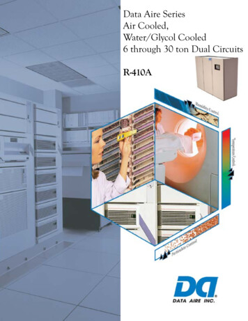
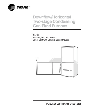
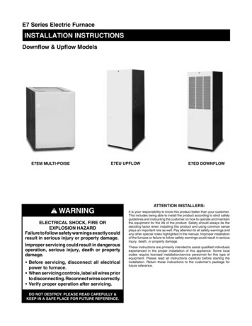
REAR WALL OF CLOSET OR ALCOVEREAR WALL OF CLOSET OR ALCOVE1 3/4" MIN.CONNECTORSFURNACES WITHSTD. RANT LINE4 1/4” X 3 3/4”5”3 3/8”10"REAR WALL OF CLOSET OR ALCOVE1 3/4"MIN.FLOOR CUT-OUT14 1/4” DIAMETERFOR DOWNFLOWFURNACES WITHROUND DUCTCONNECTORSCL3”20"FURNACEDOOROPTIONAL SUPPLYWIRE ENTRANCE3” X 6 1/4”3/4"CL3/4"10"16 5/8"FURNACE OUTLINE23 3/4"FLOOR CUT-OUT14 1/4” DIAMETERFOR UPFLOWFURNACES WITHROUND DUCTCONNECTORS17"2 3/8"MIN.FURNACE OUTLINE18 5/8"FURNACEDOOR20"STANDARD DUCT CONNECTORREAR WALL OF CLOSET OR ALCOVE23 3/4"OPTIONAL SUPPLYWIRE ENTRANCE3” X 6 1/4”3/4"3/4"STANDARD DUCT CONNECTOROPTIONALREFRIGERANT LINE3 1/8” X 5 3/4”16 5/8"17"14 1/2” X 14 1/2”FOR DOWNFLOWCLCLOPTIONALREFRIGERANT LINE3 1/8” X 5 3/4”23 3/4"FOR UPFLOWFURNACES WITHSTD. DUCTFLOOR CUT-OUTFURNACE OUTLINE17 1/2” X 14”18 5/8"23 3/4"FLOOR CUT-OUTFURNACE OUTLINE2 3/8" MIN.OPTIONALREFRIGERANT LINE4 1/4” X 3 3/4”ROUND DUCT CONNECTOR5”3 3/8”10"20"FURNACEDOORROUND DUCT CONNECTORFigure 2. Cut-Out Dimensions for Upflow FurnacesFigure 3. Cut-Out Dimensions for DownflowFurnacesStandard Duct Connector InstallationThe standard duct connector is designed for use on ducts12” in width. NOTE: Ducts narrower than 12” may notallow sufficient clearances for this type of installation.See Narrow Duct Connector section.1. Center the duct connector in the floor opening withbottom tabs resting on top of the supply air duct.2. Mark the cut-out area on the supply air duct by tracingaround the connector tabs of the duct connector. SeeFigure 5 (page 7).3. Remove the duct connector and cut out the markedarea of the supply air duct 1/4” larger than the actualcutout drawn.4. Install the duct connector back in the floor opening withthe bottom tabs extending into the supply air duct.5. Install the mounting plate (Figure 5) under the back sideof the duct connector. Align the screw holes in bothcomponents.6. Secure the duct connector and the mounting plate tothe wood floor with appropriate size screws.7. Bend the connector tabs on the bottom of the ductconnector upwards and as tight as possible againstthe supply air duct. See Figure 6 (page 7).8. Seal all connections with industrial grade sealing tapeor liquid sealant.6“X”FLOOR OPENINGSUPPLY AIR DUCTFLOORCAVITYFigure 4. Floor Cavity
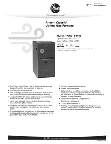
DUCT CONNECTORTYPE & PART NUMBER901987A9040082” / (51)901988A9040094-1/4” / (108)901989A9040106-1/4” / (159)901990A9040118-1/4” / (210)901991A90401210-1/4” / (260)901992A90401312-1/4” / (311)901993A904014NOTE: Dimensions shown as Inches / (Millimeter)Table 2. Duct Connector SizesNarrow Duct ConnectorsThis attachment method should be used if there isinsufficient clearance to bend the tabs on a standard 12”duct connector.1. Score and cut the top of the supply air duct as indicatedin Option 1 or Option 2 (Figure 7). With Option 1 choice,cut out the metal from the shaded area.2. Fold the two flaps (Options 1 or 2) up to form the openingfor the duct connector.3. Install the duct connector with the bottom tabs extendinginto the supply air duct.4. Bend the tabs on the bottom of the duct connectorupwards and as tight as possible against the supplyair duct. See Figure 8 (page 8).5. Form the flaps (Options 1 or 2) up against the ductconnector as tight as possible.6. Secure the duct connector flaps to the supply airduct with staples (3 minimum) or if a 2x block/joist isnot provided, use sheet metal screws (2 minimum).NOTE: The duct connector tabs may be attached tothe air duct with sheet metal screws or other suitablefasteners as long as the duct connector and the air ductare securely attached.7. Seal all connections with industrial grade sealing tapeor liquid sealant.SUPPLYAIR DUCTBEND TABS TIGHTLYAGAINST SUPPLY AIR DUCTFigure 6. Duct Connector TabsRound Duct Connector InstallationThe 14” round duct connector is designed to connectdirectly to a 14” flexible duct. NOTE: Flexible ducts musthave a minimum temperature rating of 200 F and meetall applicable codes and standards.1. Apply a bead of caulking, mastic, or other approvedsealant around bottom side of connector.2. Install and center the duct connector in the floor opening.3. Install the mounting plate under the back side of theduct connector. See Figure 9 (page 8). NOTE: Alignthe screw holes in both components.4. Secure the duct connector and the mounting plate tothe wood floor with appropriate size screws.5. Connect the round supply duct to the underside of theduct connector and secure them with field suppliedsheet metal screws.6. Seal all connections with industrial grade sealing tapeor liquid sealant.Alcove Installation1. Cut alcove rough openings to minimum dimensionsshown in Figure 10 (page 8). NOTE: The height mayincrease depending on the size of the coil compartment.2. Attach a return air method to the furnace. Dependingon the application, this could be a louvered door coilbox, frame and grille assembly, or an upflow stand withsolid door coil box.OPTION 1ORTHCULOCUEREFOLD FLAP HEREELYPPSU DUCTAIRERDUCTCONNECTORTHMOUNTINGPLATECUTORECNNCO TABSEERWOCUTHFODCUT HEREREMOVETHISFLAPOPTION 2SUPPLYAIR DUCTTHEREREMOVETHISFLAPCUT HERECUT HERECUT HEREFOLD FLAP HERE7/8” / (22)DUCT CONNECTORCUT HERESCREW DOWNFOLD FLAP HERESTANDARD DUCTFOLD FLAP HEREIF FLOOR CAVITY“X” IS:Figure 7. Narrow Air Duct OpeningsFigure 5. Standard Duct Connector Installed7
STAPLES OR SHEETMETAL SCREWSDUCT CONNECTOR TABSNARROWDUCTNARROWDUCTDUCTFLAPWallReturn Air GrilleCoil AirFilters27"(686 mm)DUCTCONNECTORSHEET METALSCREWSNARROWDUCTFigure 8. Narrow DuctsROUND DUCTCONNECTORSCREWS MOUNTINGPLATE56"(1423 mm)A/C or H/PCoil24 3/4"(629 mm)FurnaceFront29"( 737 mm)20"(508 mm)18"NearestWall or PartitionFigure 10. Alcove Installation14” SUPPLYCONNECTIONFigure 9. Round Duct Connector InstalledCloset InstallationFor closet installations, a coil box is recommended to beinstalled with the furnace. In all configurations, return airmust meet requirements found in Minimum UnobstructedAirflow section. See Figure 11 (page 9).1. Cut return air opening in desired position in door or wall,preferably above top of furnace. Refer to the MinimumUnobstructed Airflow section (page 3) for return airopening requirements.2. Insert four fasteners, securing grille to door or wall.Downflow FurnacesFor typical unducted return air downflow applications,an air-conditioner or heat-pump coil can be installed bymounting the coil directly on top of the furnace withoutadding sheet metal cavities or cutting and trimming woodpanels. Unducted return air systems may be used forcloset or alcove installations.The steps below describe installation procedures foran under-the-floor supply duct system with a ductedor unducted return air system. Duct connectors arerecommended for this application. See Table 2 (page 7).NOTE: Remove refrigerant line knockouts in furnaceonly when installing indoor coil of an air conditioner orheat pump system. Refer to instructions supplied withaccessory equipment.1. Route 240V supply circuit(s) and 24V wiring to closetor alcove. See Figure 17 (page 13) or Figure 18 (page13) for locations.2. Remove furnace front door and slide back until bottomslots in rear of unit engage with both tabs of optionalrear mounting plate. If mounting plate is not used, anequivalent method of securing the rear of the unit maybe used as long as it prevents displacement duringtransport if used in a manufactured home.8NOTE: The furnace does not need to be positionedagainst the rear mounting plate. The tabs will engageinto the slots and allow approximately 1/2” of furnaceadjustment front to back and side to side.4. Secure front of unit with one or more fasteners atmounting hole(s) provided or at tie-down tab. See Figure17 (page 13) or Figure 18 (page 13).5. See Electrical Wiring section (page 10) to completefurnace installation.Upflow FurnacesThe following steps describe installation instructions foran overhead supply duct system with a return air systemthat can be either over the floor (unducted) or throughthe floor (ducted).NOTE: Remove refrigerant line knockouts in furnace onlywhen installing indoor coil from an air conditioner or heatpump system.Refer to instructions supplied with accessory equipment.Over-the-Floor Return Air System (Non-Ducted)1. If floor underneath furnace is made of combustiblematerial, locate a pan fabricated of non-combustiblematerial with 1” upturned flanges under furnace returnair opening. See Figure 12 (page 9).2. Use optional upflow stand (refer to the technicalspecifications literature for part number) with filters orconstruct a suitably braced mounting platform in closet.See Figure 13 (page 9).3. Route 240V supply circuit(s) and 24V wiring to closet.See Figure 17 (page 13) or Figure 18 (page 13) forappropriate locations.4. Position optional coil cabinet onto upflow stand ormounting platform and secure with three or morefasteners.5. Position furnace in upflow mode onto coil cabinet andsecure with two or more fasteners.6. Use optional upflow duct connector or field suppliedconnector to attach furnace to overhead supply duct.See Figure 13.
7. Install return air grille in closet preferably at same levelas upflow stand or below mounting platform. See Figure12.Provide min. 235sq. in. (1516 cm )open free area infront or side wallor in top ofcloset door0" SideClearanceto FurnaceCabinet(1526"mm)CLOSET DOORStandard Closet InstallationProvide min. 250sq. in. (1613 cm2 )open free area infront or side wallor in top ofcloset doorThrough-the-Floor Return Air System (Ducted)1. Prepare Floor Opening(s):a. Mark floor openings as shown in Figure 2 (page 6).
E7ED Models: Make sure there is an 18"x20" filter in the top filter rack and an 18"x30" filter in the front filter rack. Without A/C or H/P uncased coil Use the filter supplied with the furnace. Make sure the filter is installed mat side down between the filter retainer and furnace top. With A/C or H/P uncased coil