Transcription
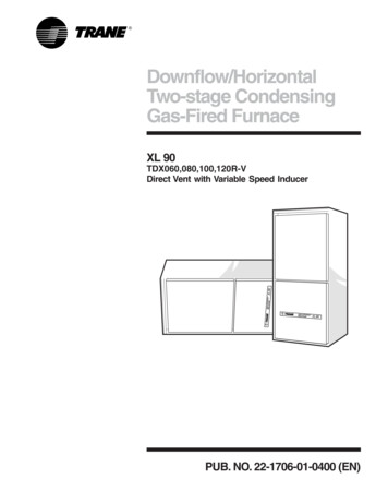
Downflow/HorizontalTwo-stage CondensingGas-Fired FurnaceXL 90TDX060,080,100,120R-VDirect Vent with Variable Speed InducerPUB. NO. 22-1706-01-0400 (EN)
GeneralFeaturesNatural Gas ModelsCentral heating furnace designs arecertified by the American Gas Associationfor both natural and L.P. gas. Limit settingand rating data were established andapproved under standard ratingconditions using American NationalStandards Institute standards.Safe OperationThe Integrated System Control has solidstate devices, which continuously monitorfor presence of flame, when the systemis in the heating mode of operation. Dualsolenoid combination gas valve andregulator provide extra safety.Quick HeatingDurable, cycle tested, heavy gaugealuminized steel heat exchangerquickly transfers heat to provide warmconditioned air to the structure. Lowenergy power vent blower, to increaseefficiency and provide a positive discharge of gas fumes to the outside.BurnersMulti-port In-shot burners will give yearsof quiet and efficient service. All modelscan be converted to L.P. gas withoutchanging burners.Integrated System ControlExclusively designed operationalprogram provides total control of furnacelimit sensors, blowers, gas valve, flamecontrol and includes self diagnostics forease of service. Also contains connection points for E.A.C./humidifier. American Standard Inc. 20002Condensate DrainBuilt-in trap which can drain from eitherside when the furnace is installed upflow.Air DeliveryThe variable speed, direct drive blowermotor, has sufficient airflow for mostheating and cooling requirements, willswitch from heating to cooling speeds ondemand from room thermostat. Theblower door safety switch will prevent orterminate furnace operation when theblower door is removed.Secondary Heat ExchangerThe XL 90 has a special type 29-4C stainless steel secondary heat exchanger to reclaim heat from flue gaseswhich would normally be lost outside.StylingHeavy gauge steel and “wrap-around”cabinet construction is used in thecabinet with baked-on enamel finish forstrength and beauty. The heat exchangersection of the cabinet is completely linedwith foil faced fiberglass insulation. Thisresults in quiet and efficient operationdue to the excellent acoustical andinsulating qualities of fiberglass. Built-inbottom pan and alternate bottom, left orright side return air connection provision.Features And General OperationThe XL 90 High Efficiency Gas Furnacesemploy an Adaptive Silicon Nitride HotSurface Ignition system, which eliminates the waste of a constant burningpilot. The integrated system control lightsthe main burners upon a demand forheat from the room thermostat. Completefront service access.a. Low energy power venter.b. Vent proving pressure switch.22-1706-01-0400 (EN)
ContentsFeature Summary2Features and Benefits445Standard EquipmentOptional EquipmentGeneral -1706-01-0400 (EN)66666Performance Data7Electrical Data9Field Wiring10Dimensions143
Features andBenefitsXL 90 STANDARD EQUIPMENT Direct or nondirect vent application Adjustable fan off times Convertible to horizontal on left side Single pipe venting Power supply 115/1/60 Cleanable high velocity filters 2-stage gas valve Heavy gauge reinforced wrap-aroundsteel cabinet Variable speed inducer motor Adaptive Silicon Nitride hot surfaceigniter Super quiet performance Integrated system control Optional L.P. conversion kit Heavy gauge aluminized steel heatexchanger Left/right gas connection Blower door safety switch Multi-port In-shot burners Alternate bottom/left/right return air invertical position Slide-out blower assembly Complete front service access Limited lifetime warranty on primaryand secondary heat exchangers tooriginal owner One-year parts warranty Three-year warranty on integratedcontrol and hot surface igniter Direct drive, 4 speed motors422-1706-01-0400 (EN)
Features andBenefitsXL 90 OPTIONAL EQUIPMENTThermostat, Mechanical 2-Stage Heating/1-Stage Cooling . BAYSTAT241 [Thermostat, Mechanical Heating Only With Fan Switch . BAYSTAT303 [Thermostat, Heating/Cooling Single Stage (Mounts Horizontally) . AY28X092 [Thermostat, Heating/Cooling Single Stage (Mounts Vertically) . BAYSTAT305 [Thermostat, Electronic Programmable 2-Stage Heating/2-Stage Cooling . BAYSTAT302B [Thermostat, Electronic Programmable 1-Stage Heating/1-Stage Cooling . BAYSTAT300 [Propane Conversion Kit . BAYLPKT210A [Electronic Air Filter, “Perfect Fit” Super Efficiency (17-1/2" Wide Gas Furnace) . TFE175A9FR0 [Electronic Air Filter, “Perfect Fit” Super Efficiency (21" Wide Gas Furnace) . TFE210A9FR0 [Electronic Air Filter, “Perfect Fit” Super Efficiency (24-1/2" Wide Gas Furnace) . TFE245A9FR0 [Electronic Air Filter, “Perfect Fit” High Efficiency (17-1/2" Wide Gas Furnace) . TFM175A9FR0 [Electronic Air Filter, “Perfect Fit” High Efficiency (21" Wide Gas Furnace) . TFM210A9FR0 [Electronic Air Filter, “Perfect Fit” High Efficiency (24-1/2" Wide Gas Furnace) . TFM245A9FR0 [Electronic Air Filter, “Perfect Fit” Standard Efficiency (17-1/2" Wide Gas Furnace) . TFP175A9FR0 [Electronic Air Filter, “Perfect Fit” Standard Efficiency (21" Wide Gas Furnace) . TFP210A9FR0 [Electronic Air Filter, “Perfect Fit” Standard Efficiency (24-1/2" Wide Gas Furnace) . TFP245A9FR0 [Coil Enclosure (17-1/2" Wide Cabinets) . BAYCLE1700 [Coil Enclosure (21" Wide Cabinets) . BAYCLE2100 [Coil Enclosure (24-1/2" Wide Cabinets) . BAYCLE2400 [Downflow Subbase . BAYBASE205 [High Altitude Switch (060) . BAYHALT245 [High Altitude Switch (080,100) . BAYHALT246 [High Altitude Switch (120) . BAYHALT247 [Concentric Vent Termination . BAYVENT100A [Sidewall Vent Termination . BAYVENT200B [Manufactured/Mobile Home Kit . BAYMFGH100A [22-1706-01-0400 (EN)5]]]]]]]]]]]]]]]]]]]]]]]]]]
GeneralDataTDX-R-V PRODUCT X120R960V3900036000600005500092.035 - 655200048000800007400092.535 - 6565000600001000009300093.045 - 75780007200012000011100092.545 - 75DIRECT10 x 814SEE FAN PERF. TABLE1/31075115/1/60DIRECT11 x 814SEE FAN PERF. TABLE1/21075115/1/60DIRECT11 x 1014SEE FAN PERF. TABLE1/21075115/1/60DIRECT11 x 1014SEE FAN PERF. TABLE3/41075115/1/60CENTRIFUGALDIRECT - VARIABLE1/15 - 5000115/1/601.1CENTRIFUGALDIRECT - VARIABLE1/15 - 5000115/1/601.1CENTRIFUGALDIRECT - VARIABLE1/15 - 5000115/1/601.1CENTRIFUGALDIRECT - VARIABLE1/15 - 5000115/1/601.1YESHIGH VELOCITY2 - 14 X 20 X 1YESHIGH VELOCITY2 - 14 X 20 X 1YESHIGH VELOCITY2 - 16 X 20 X 1YESHIGH VELOCITY2 - 16 X 20 X 12 ROUND2 ROUND2 ROUND3 ROUNDALUMINIZED STEEL TYPE 1ALUMINIZED STEEL TYPE 1ALUMINIZED STEEL TYPE 1ALUMINIZED STEEL TYPE 1202020203 - 453 - 564 - 454 - 565 - 455 - 566 - 456 - 56REDUNDANT - TWO STAGEREDUNDANT - TWO STAGEREDUNDANT - TWO STAGEREDUNDANT - TWO STAGEMODELRATINGS21st Stage Input BTUH1st Stage Capacity BTUH (ICS)32nd Stage Input BTUH2nd Stage Capacity BTUH (ICS)3AFUE (ICS)Temp. Rise (Min.-Max.) F.BLOWER DRIVEDia.-Width (In.)No. UsedSpeeds (No.)CFM vs. in. w.g.Motor HPR.P.M.Volts/Ph/HzCOMBUSTION FAN - TYPEDrive - No. SpeedsMotor HP - RPMVolts/Ph/HzFL AmpsFILTER — Furnished?Type RecommendedFilter (No.-Size-Thk.)VENT — Size (In.)HEAT EXCHANGERType-Fired-UnfiredGauge (Fired)ORIFICES — MainNat. Gas. Qty. — Drill SizeL.P. Gas Qty. — Drill SizeGAS VALVEDIRECT IGNITION DEVICETypeHOT SURFACE IGNITERHOT SURFACE IGNITERHOT SURFACE IGNITERHOT SURFACE IGNITERBURNERS — TypeNumberIN-SHOT4IN-SHOT4IN-SHOT5IN-SHOT6POWER CONN. — V/Ph/Hz4Ampacity (In Amps)Fuse Size — Max. /1/6012.9150.500.500.500.50DUCT CONN.SEE OUTLINE DRAWINGSEE OUTLINE DRAWINGSEE OUTLINE DRAWINGSEE OUTLINE DRAWINGDIMENSIONSCrated (In.)UncratedHXWXD41-3/4 X 19-1/2 X 30-1/2SEE OUTLINE DRAWINGHXWXD41-3/4 X 19-1/2 X 30-1/2SEE OUTLINE DRAWINGHXWXD41-3/4 X 23 X 30-1/2SEE OUTLINE DRAWINGHXWXD41-3/4 X 26-1/2 X 30-1/2SEE OUTLINE DRAWING155/145168/158185/175206/196PIPE CONN. SIZE (IN.)WEIGHTShipping (Lbs.)/Net (Lbs.)1 Central Furnace heating designs are certified by the American Gas Association Inc. Laboratories.2 Ratings shown are for elevations up to 2000 feet. For elevations above 2000 feet; Ratings should be reduced at the rate of 4% for each 1000 feet above sea level.3 Based on U.S. Government Standard Tests.4 The above wiring specifications are in accordance with National Electrical Code; however, installations must comply with local codes.622-1706-01-0400 (EN)
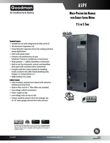
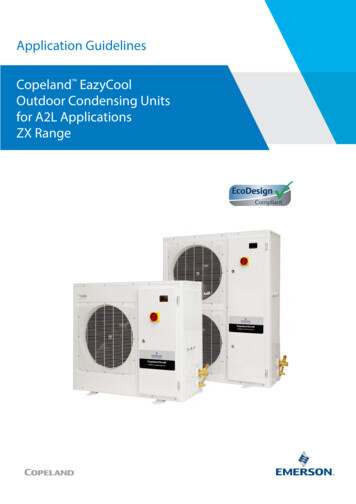
PerformanceDataTDX-R-VFURNACE AIRFLOW (CFM) VS. EXTERNAL STATIC PRESSURE (in. 960V22-1706-01-0400 (EN)4321432143214321-SPEED TAP0.100.200.300.400.500.600.700.800.90HIGH - BlackMED.-HIGH - BlueMED.-LOW - YellowLOW - RedHIGH - BlackMED.-HIGH - BlueMED.-LOW - YellowLOW - RedHIGH - BlackMED.-HIGH - BlueMED.-LOW - YellowLOW - RedHIGH - BlackMED.-HIGH - BlueMED.-LOW - YellowLOW - 711597
PerformanceDataVENT LENGTH TABLEMAXIMUM TOTAL EQUIVALENT LENGTH IN FEETFOR VENT AND INLET AIR (SEE NOTES)ALTITUDE0-7,000 Feet2 INCH PIPE2.5 INCH PIPE3 INCH 948VNot Allowed60200TDX120R960VNot AllowedNot Allowed2007,000-9,500 Feet2 INCH PIPE2.5 INCH PIPE3 INCH 48VNot Allowed30100TDX120R960VNot AllowedNot Allowed1009,500-12,000 Feet2 INCH PIPE2.5 INCH PIPE3 INCH PIPETDX060R936V505050TDX080R942VNot Allowed3050TDX100R948VNot AllowedNot Allowed50TDX120R960VNot AllowedNot Allowed50NOTES:1. Minimum vent length for all models: 3' horizontal and vertical.2. DO NOT MIX PIPE DIAMETERS IN THE SAME LENGTH OF PIPE OUTSIDE THE FURNACE CABINET (Except adapters atthe top of the furnace).3. MAXIMUM PIPE LENGTHS MUST NOT BE EXCEEDED! THE LENGTH SHOWN IS NOT A COMBINED TOTAL, IT IS THEMAXIMUM LENGTH OF EACH (Vent or Inlet air pipes).4. One SHORT radius 90 elbow is equivalent to 10' of 3" pipe and one LONG radius elbow is equivalent to 6' of 3" pipe. One90 elbow is equivalent to 7½' of 2½" pipe or 5' of 2" pipe. Two 45 elbows equal one 90 elbow.5. The termination tee or bend must be included in the total number of elbows. If the BAYVENT100A termination kit is used, theequivalent length of pipe is 5 feet. BAYVENT200A/B equivalent length is 0 feet.6. Pipe adapters are field supplied (except 120).822-1706-01-0400 (EN)
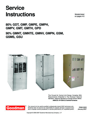
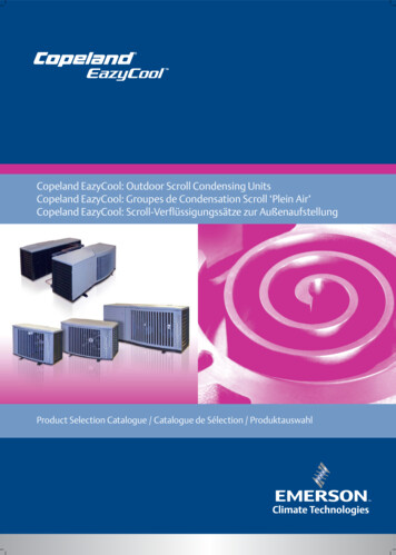
ElectricalDataSCHEMATIC DIAGRAMS FOR GAS FURNACESLEGENDTDX060,080,100,120R-VFrom Dwg. 21D341250 P0222-1706-01-0400 (EN)9
FieldWiringFIELD WIRING DIAGRAM FOR SINGLE STAGE HEATINGFrom Dwg. 21B341333 Rev. 0FIELD WIRING DIAGRAM FOR 2 STAGE HEATING THERMOSTATFrom Dwg. 21B341332 Rev. 01022-1706-01-0400 (EN)
FieldWiringFIELD WIRING DIAGRAM FOR SINGLE STAGE HEATING/COOLING(OUTDOOR SECTION WITHOUT TRANSFORMER)From Dwg. 21B341335 Rev. 0FIELD WIRING DIAGRAM FOR 2 STAGE HEATING SINGLE STAGE COOLING(OUTDOOR SECTION WITHOUT TRANSFORMER)From Dwg. 21B341334 Rev. 022-1706-01-0400 (EN)11
TwinningField WiringTwinning Connection DiagramFor Twinning UX/DX-R Furnaces - 2 Stage Heat / 2 Stage Cooling ThermostatFrom Dwg. 21B341338 Rev. 0Twinning Connection DiagramFor Twinning UX/DX-R Furnaces - 2 Stage Heat / 1 Stage Cooling ThermostatFrom Dwg. 21B341337 Rev. 01222-1706-01-0400 (EN)
TwinningField WiringTwinning Connection DiagramFor Twinning UX/DX-R Furnaces - 1 Stage Heat / 1 Stage Cooling ThermostatFrom Dwg. 21B341336 Rev. 022-1706-01-0400 (EN)13
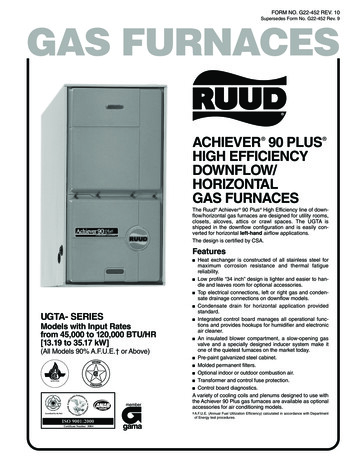
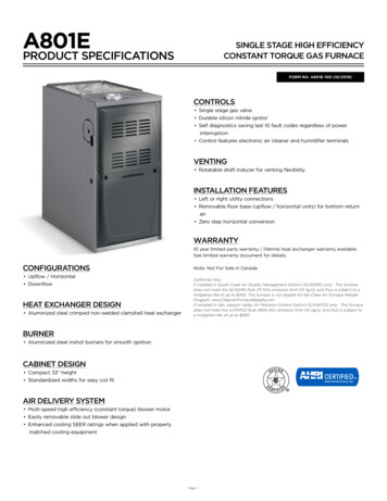
DimensionsTDX-R-V OUTLINE DRAWING(ALL DIMENSIONS ARE IN "10"3"TDX100R948VTDX120R960V24-1/2" 2-15/16" 23-1/4"Notes:1. TDX100R960V requires 2-1/2" or 3" and TDX120R960Vrequires a 3" diameter vent pipe.2. Clearance required at top of plenum is 1"From Dwg. 21C340762 Rev. 31422-1706-01-0400 (EN)
Notes22-1706-01-0400 (EN)15
P.I.The Trane CompanyUnitary Products Group6200 Troup HighwayTyler, TX 75707-9010www.trane.comAn American Standard CompanySince The Trane Company has a policy of continuous product and product data improvement, it reserves theright to change design and specifications without notice.
Downflow/Horizontal Two-stage Condensing Gas-Fired Furnace XL 90 TDX060,080,100,120R-V Direct Vent with Variable Speed Inducer PUB. NO. 22-1706-01-0400 (EN)