Transcription
UPFLOW/DOWNFLOW COILSINSTALLATION INSTRUCTIONS1. Important Safety Instructions3. Codes & RegulationsThe following symbols and labels are used throughout this manualto indicate immediate or potential safety hazards. It is the owner’sand installer’s responsibility to read and comply with all safety information and instructions accompanying these symbols. Failureto heed safety information increases the risk of personal injury,property damage, and/or product damage.This product is designed and manufactured to comply with nationalcodes. Installation in accordance with such codes and/or prevailinglocal codes/regulations is the responsibility of the installer. Themanufacturer assumes no responsibility for equipment installedin violation of any codes or regulations.The United States Environmental Protection Agency (EPA) hasissued various regulations regarding the introduction and disposalof refrigerants. Failure to follow these regulations may harm theenvironment and can lead to the imposition of substantial fines.Should you have any questions please contact the local office ofthe EPA.HIGH VOLTAGE!DISCONNECT ALL POWER BEFORE SERVICING ORINSTALLING THIS UNIT. MULTIPLE POWER SOURCESMAY BE PRESENT. FAILURE TO DO SO MAY CAUSE PROPERTYDAMAGE, PERSONAL INJURY OR DEATH.ONLY PERSONNEL THAT HAVE BEEN TRAINED TO INSTALL, ADJUST, SERVICE ORREPAIR (HEREINAFTER, “SERVICE”) THE EQUIPMENT SPECIFIED IN THIS MANUALSHOULD SERVICE THE EQUIPMENT. THE MANUFACTURER WILL NOT BE RESPONSIBLEFOR ANY INJURY OR PROPERTY DAMAGE ARISING FROM IMPROPER SERVICE ORSERVICE PROCEDURES. IF YOU SERVICE THIS UNIT, YOU ASSUME RESPONSIBILITYFOR ANY INJURY OR PROPERTY DAMAGE WHICH MAY RESULT. IN ADDITION, INJURISDICTIONS THAT REQUIRE ONE OR MORE LICENSES TO SERVICE THE EQUIPMENTSPECIFIED IN THIS MANUAL, ONLY LICENSED PERSONNEL SHOULD SERVICE THEEQUIPMENT. IMPROPER INSTALLATION, ADJUSTMENT, SERVICING OR REPAIR OFTHE EQUIPMENT SPECIFIED IN THIS MANUAL, OR ATTEMPTING TO INSTALL, ADJUST,SERVICE OR REPAIR THE EQUIPMENT SPECIFIED IN THIS MANUAL WITHOUT PROPERTRAINING MAY RESULT IN PRODUCT DAMAGE, PROPERTY DAMAGE, PERSONALINJURY OR DEATH .Inspect the unit to verify all required components are present andintact. Report any missing components immediately to the manufacturer or to the distributor. Make sure to include the full productmodel number and serial number when reporting and/or obtainingservice parts. Replacement parts for this product are availablethrough your contractor or local distributor. For the location of yournearest distributor consult the white business pages, the yellowpage section of the local telephone book or contact:HOMEOWNER SUPPORTGOODMAN MANUFACTURING COMPANY, L.P.19001 KERMIER ROADWALLER, TEXAS 77484877– 254 – 47295. Pre-Installation Instructions5.1 Preparation2. Shipping InspectionUpon receiving the product, inspect it for damage from shipment.Shipping damage, and subsequent investigation is the responsibilityof the carrier. Verify the model number, specifications, and accessories are correct prior to installation. The distributor or manufacturerwill not accept claims from dealers for transportation damage orinstallation of incorrectly shipped units.2.1 HandlingUse caution when transporting / carrying unit. Do not carry unitwith hooks or sharp object. The preferred method of carryingthe unit after arrival at the job site is to carry by two-wheelhand truck from the back or sides or by hand by carrying at thecabinet corners.IOG-4010E06/20214. Replacement PartsKeep this document with the unit. Carefully read all instructionsfor the installation prior to installing product. Make sure eachstep or procedure is understood and any special considerationsare taken into account before starting installation. Assemble alltools, hardware and supplies needed to complete the installation. Some items may need to be purchased locally. Make sureeverything needed to install the product is on hand beforestarting.5.2 ClearancesRefrigerant lines must be routed depending on configurationof unit to maintain the required 24” minimum clearance forservice. Consult all appropriate regulatory codes prior to determining final clearances. In installations that may lead to physicaldamage (i.e. a garage) it is advised to install a protective barrierto prevent such damage. Always install units such that a positiveslope in condensate line (1/4” per foot) is allowed.19001 Kermier Rd, Waller, TX 77484 2005-2006, 2012-2013, 2015-2021 Goodman Manufacturing Company, L.P.www.goodmanmfg.com
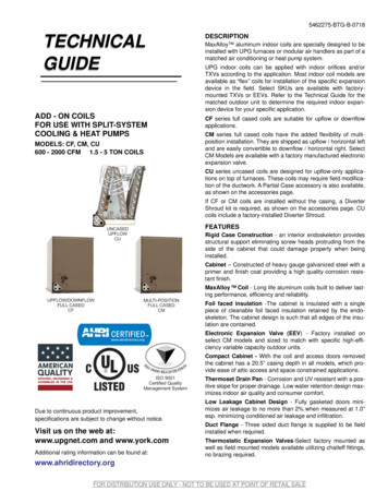
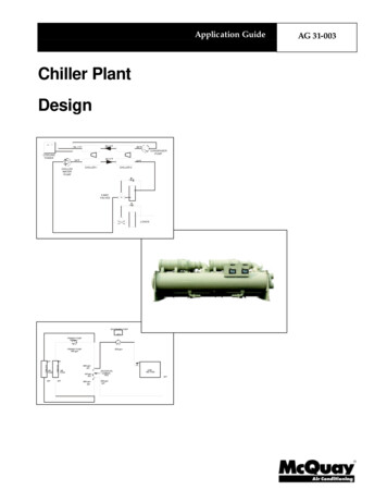
6. Application InformationIf the uncased coil is to be installed on top of a gas furnace, allowenough space between the top to the furnace and the bottom ofthe plastic coil drain pan to have a free flow of air.A minimum of 2.0” distance from the top of the furnace and thebottom of the coil pan is required.NOTE: The coil must be installed with the line set and drain openingsto the front of the furnace.Coils are designed for indoor installation only and must be installeddownstream (discharge air) of the furnace. The CAPF/CAPT productline may be installed in upflow or downflow orientations.7. Condensate Drain PipingIn all cooling applications where condensate overflow may causedamage, a secondary drain pan must be provided by the installerand placed under the entire unit with a separate drain line properly sloped and terminated in an area visible to the owner. Thissecondary drain pan can provide extra protection to the area underthe unit should the primary drain plug up and overflow. For coilswith “A” Cabinets (14” wide), use float switch if secondary drainline is not installed. Refer to product nomenclature from productspecification literature to identify coil models with “A” cabinets.As expressed in our product warranty, we will not be liable for anydamages, structural or otherwise due to the failure to follow thisinstallation requirement.Condensate drain connections are located in the drain pan at thebottom of the coil/enclosure assembly. Use the female (3/4” FPT)threaded fitting that protrudes outside of the enclosure for externalconnections. The connectors required are 3/4” NPT male, eitherPVC or metal pipe, and must be hand tightened to a torque of nomore than 37 in-lbs. to prevent damage to the drain pan connection.An insertion depth between .36 to .49 inches (3-5 turns) should beexpected at this torque. Insulate PVC drain lines/pipes with highheat resistive tape within 1” furnace flue/vent pipe. Foil-MasticSealant tape is the preferred wrapping material.1. Ensure drain pan hole is NOT obstructed.2. To prevent potential sweating and dripping on finished space,it may be necessary to insulate the condensate drain linelocated inside the building. Use Armaflex or similar material.A Secondary Condensate Drain Connection, now called for by manybuilding codes, has been provided. Pitch the drain line 1/4” perfoot to provide free drainage. Provide required support to drainline to prevent bowing. Install a condensate trap in the primarydrain line to ensure proper drainage. If the secondary drain line isrequired, run the line separately from the primary drain and endit where condensate discharge can be easily seen.Figure 1NOTE: Water coming from the secondary line means the coil primary drain is plugged and needs immediate attention.Install a trap in the drain line below the bottom of the drain pan(Figure 1). If using a copper drain line, solder a short piece of pipe,minimum 6” length, to the connector before installing a drain fitting.DO NOT over torque the 3/4” copper connector to the plastic drainconnection. Using a wet rag or heatsink material on the short pieceto protect the plastic drain pan, complete the drain line installation.Use Figure 2 as a template for typical drain pipe routing. This figureshows how to avoid interference with vent piping.CAUTIONIF SECONDARY DRAIN IS NOT INSTALLED, THE SECONDARY ACCESSMUST BE PLUGGED.8. Plastic Drain Pan Application2” MIN.DO NOT USE THE COIL PAN SHIPPED WITH THE UNIT ON OIL FURNACESOR ANY APPLICATION WHERE THE TEMPERATURE OF THE DRAIN PAN MAYEXCEED 300 F. A HIGH TEMPERATURE DRAIN PAN SUCH AS KITS HTP-A,-B, -C AND -D FOR NORMAL CABINET WIDTHS OF 14, 17.5, 21 AND24.5 INCHES, RESPECTIVELY, SHOULD BE USED FOR APPLICATIONS WHERETHE TEMPERATURE EXCEEDS 300 F AND BELOW 450 F. A FIELDFABRICATED METAL DRAIN PAN CAN ALSO BE USED FOR APPLICATIONSWHERE TEMPERATURE EXCEEDS 300 F.FAILURE TO FOLLOW THIS WARNING MAY RESULT IN PROPERTY DAMAGEAND /OR PERSONAL INJURY.3” MIN.Figure 22
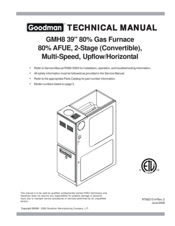
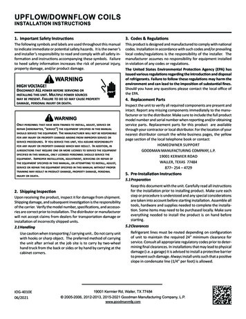
NOTE: Refrigerant tubing must be routed to allow adequate accessfor servicing and maintenance of the unit.Do not handle coil assembly with manifold or flowrator tubes.Doing so may result in damage to the tubing joints. Always useclean gloves for handling coil assemblies.9.1 Tubing Size/LengthA CHASSIS WITH 80%For the correct tubing size, follow the specification for the condenser/heat pump. Give special consideration to minimizingthe length of refrigerant tubing when installing coils. Refer toRemote Cooling/Heat Pump Technical Publication TP-107* LongLine Set Application R-410A for guidelines for line lengths over80’. Leave a minimum 3” straight in line set from braze jointsbefore any bends.A CHASSIS WITH 90%9.2 Tubing PreparationAll cut ends are to be round, burr free, and cleaned. Any othercondition increases the chance of a refrigerant leak. Use a pipecutter to remove the closed end of the spun closed suction line.9.3 BrazingB, C, D CHASSIS WITH 80%Braze joints should be made only with the connections provided external to the cabinet. Do not alter the cabinet nor brazeinside the cabinet. To avoid overheating after brazing, quenchall brazed joints with water or a wet rag.B, C, D CHASSIS WITH 90%Figure 38.1 Condensate Drain Pan Break-away FeatureThe drain pan (0161D00116) possesses a break-away feature onthe lip located on the front-top and rear-top of the drain pan.This feature is to be used for uncased installations, as necessary.The force required to break the lip is 18lbf uniformly distributedover the feature. A force of 8lbf localized on the corner of thelip can also be applied. (Applies only for A-size Cabinet)APPLYING TOO MUCH HEAT TO ANY TUBE CAN MELT THE TUBE. TORCHHEAT REQUIRED TO BRAZE TUBES OF VARIOUS SIZES MUST BEPROPORTIONAL TO THE SIZE OF THE TUBE.SERVICE PERSONNEL MUST USE THE APPROPRIATE HEAT LEVEL FOR THESIZE OF THE TUBE BEING BRAZED.9.4 Special Instructions for Flowrator (Piston) VersionCoils in flowrator version are equipped with a check style flowrator for refrigerant management. For most installations withmatching applications, no change to the flowrator piston is required. However, in mix-matched applications, a piston changemay be required. See the piston kit chart or consult your localdistributor for details regarding mix-matched piston sizing. Ifthe mix-matched application requires a different piston size,change the piston in the distributor on the indoor coil beforeinstalling the coil and follow the procedure shown below.9.5 Tubing Connections for Flowrator ModelFigure 3.11. Loosen the 13/16 nut 1 TURN ONLY to allow high pressuretracer gas to escape. No gas indicates a possible leak.9. Refrigerant Lines2. After the gas has escaped, remove the nut and discard theplastic or brass cap.CAUTION3. Remove the check piston to verify it is correct and then replace the piston. See piston kit chart in instructions.THE COIL IS SHIPPED UNDER PRESSURE WITH AN R-410A GASMIXTURE. USE APPROPRIATE SERVICE TOOLS AND FOLLOW THESEINSTRUCTIONS TO PREVENT INJURY.4. Use a tube cutter to remove the spin closure on the suctionline. DO NOT USE A CUTTING METHOD THAT WOULD RESULTIN THE GENERATION OF COPPER SHAVINGS OR COPPER DUST.5. Slide the 13/16 nut into place on the tailpiece supplied in theliterature bag or with the unit.A QUENCHING CLOTH IS STRONGLY RECOMMENDED TO PREVENTSCORCHING OR MARRING OF THE EQUIPMENT FINISH WHEN BRAZINGCLOSE TO THE PAINTED SURFACES. USE BRAZING ALLOY OF 5%MINIMUM SILVER CONTENT.6. Insert liquid line into the supplied tailpiece.3
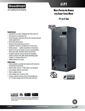
LIQUIDLINERUBBERGROMMETLIQUIDLINE SETFigure 5.25. Insert liquid line set into liquid tube expansion and slidegrommet about 18” away from braze joint.Figure 56. Insert suction line set into suction tube expansion and slideinsulation and grommet about 18” away from braze joint.7. Insert the suction line into the connection, slide the insulationand the rubber grommet at least 18” away from the brazejoint. Braze both liquid and suction line joints.7. Braze suction and liquid line joints.8. AFTER THE TAILPIECE HAS COOLED, confirm position of thewhite Teflon seal and hand tighten the 13/16 nut.10. Supply Duct Connection1. Top flanges can be bent for ease in installation to the ductflanges. (See Figure 6)CAUTIONEXCESSIVE TORQUE CAN CAUSE ORIFICES TO STICK. USE THE PROPERTORQUE SETTINGS WHEN TIGHTENING ORIFICES.9. Torque the 13/16” nut to 10-20 ft-lbs. or 1/6 turn past handtight.Unfolded View10. Replace suction line grommet and insulation.Top Flange Detail View9.6 Tubing Connections for TXV VersionTXV models come with factory installed non-adjustable TXVwith the bulb permanently located on the suction tube.1. Remove coil access panel.2. Remove access valve fitting cap and depress the valve stemin access fitting to release pressure. No pressure indicatespossible leak.3. Replace the refrigerant tubing panel.4. Remove the spin closure on both the liquid and suction tubesusing a tubing cutter. DO NOT USE A CUTTING METHOD THATWOULD RESULT IN THE GENERATION OF COPPER SHAVINGSOR COPPER DUST.SUCTIONTUBEFILLER PLATESUCTIONLINE SETFigure 62. A duct flange kit can also be purchased from your distributor.(See Figure 7)RUBBERGROMMET 14 inch chassis - CLDUCTFLGAFigure 5.1 17.5 inch chassis - CLDUCTFLGB 21 inch chassis - CLDUCTFLGC4 24.5 inch chassis - CLDUCTFLGD
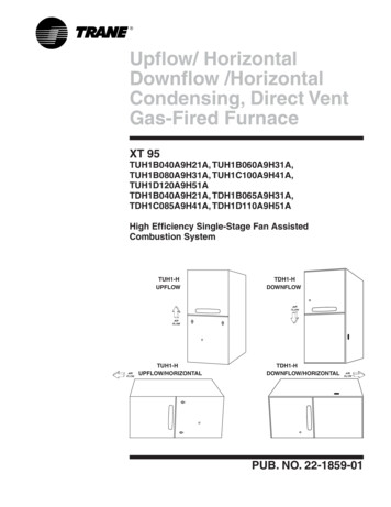
12. Sealing Along The Panel GapIMPORTANT NOTE: To prevent cabinet sweating andairflow leak, apply field provided insulation tape alongall joining surfaces between the coil, gas furnace, ductwork and panels. See Figure 8.Apply Insulation Tape13.Figure 7This unit is equipped with an aluminum tube evaporator coil. Thesafest way to clean the evaporator coil is to simply flush the coilwith water. This cleaning practice remains as the recommendedcleaning method for both copper tube and aluminum tube residential evaporator coils.It has been determined that many coil cleaners and drain pan tablets contain corrosive chemicals that can be harmful to aluminumtube and fin evaporator coils. Even a one-time application of thesecorrosive chemicals can cause premature aluminum evaporator coilfailure. Any cleaners that contain corrosive chemicals including,but not limited to, chlorine and hydroxides, should not be used.An alternate cleaning method is to use one of the products listed inTP-109* to clean the coils. The cleaners listed are the only agentsdeemed safe and approved for use to clean round tube aluminumcoils. TP-109 is also available on the web site in Partner Link Service Toolkit.10. Filler PlatesFiller plates are supplied on all 17.5, 21, & 24.5 inch chassis to beused for adapting the unit to a furnace one size smaller. If theplenum and furnace openings are the same size, the filler platesmust be removed. See Figure 6.11.Figure 8Aluminum Indoor Coil Cleaning(Qualified Servicer Only)Return DuctworkDO NOT TERMINATE THE RETURN DUCTWORK IN AN AREATHAT CAN INTRODUCE TOXIC OR OBJECTIONABLE FUMES/ODORS INTO THE DUCTWORK.NOTE: Ensure coils are rinsed well after use of any chemical cleaners.5
Air Handler / CoilModel NumberSerial NumberELECTRICALLine Voltage (Measure L1 and L2 Voltage)Secondary Voltage (Measure Transformer Output Voltage)Blower AmpsHeat Strip 1 - AmpsHeat Strip 2 - AmpsBLOWER EXTERNAL STATIC PRESSUREReturn Air Static PressureSupply Air Static PressureTotal External Static Pressure (Ignoring /- from the reading above, add total here)TEMPERATURESReturn Air Temperature (Dry bulb / Wet bulb)Cooling Supply Air Temperature (Dry bulb / Wet bulb)Heating Supply Air TemperatureTemperature RiseDelta T (Difference between Supply and Return Temperatures)L1 - L2R-CAir Handler / Coil - (Inverter Matched)INVERTER AH / COIL ONLYCheck EEV and EEV wiring is secure (no adjustment required)Additional ChecksCheck wire routings for any rubbingCheck product for proper drainingCheck screw tightness on blower wheelCheck factory wiring and wire connectionsCheck product for proper clearances as noted by installtion instructions F to C formula: ( F - 32) divided by 1.8 C C to F formula: ( C multiplied by 1.8) 32 F6IN. W.C.IN. W.C.IN. W.C.DB FDB FDB FDB FDB FWB FWB F
THIS PAGE WAS LEFT BLANK INTENTIONALLY7
CUSTOMER FEEDBACKWe are very interested in all product comments.Please fill out the feedback form on one of the following links:Goodman Brand Products: (http://www.goodmanmfg.com/about/contact-us).Amana Brand Products: (http://www.amana-hac.com/about-us/contact-us).You can also scan the QR code on the right for the product brandyou purchased to be directed to the feedback page.PRODUCT REGISTRATIONThank you for your recent purchase. Though not required to get the protection ofthe standard warranty, registering your product is a relatively short process, andentitles you to additional warranty protection, except that failure by California andQuebec residents to register their product does not diminish their warranty rights.For Product Registration, please register as follows:Goodman Brand products: Amana Brand products: (http://www.amana-hac.com/product-registration)You can also scan the QR code on the right for the product brandyou purchased to be directed to the Product Registration page.GOODMAN BRANDGOODMAN BRANDAMANA BRANDAMANA BRANDNOTE: SPECIFICATIONS AND PERFORMANCE DATA LISTED HEREIN ARE SUBJECT TO CHANGE WITHOUT NOTICEVisit our websites at www.goodmanmfg.com or amana-hac.com for information on: Products Warranties Customer Services Parts Contractor Programs and Training Financing Options19001 Kermier Rd, Waller, TX 77484 2005-2006, 2012-2013, 2015-2021 Goodman Manufacturing Company, L.P.www.goodmanmfg.com8
GOODMAN MANUFACTURING COMPANY, L.P. 19001 KERMIER ROAD WALLER, TEXAS 77484 877- 254 - 4729 5. Pre-Installation Instructions 5.1 Preparation Keep this document with the unit. Carefully read all instructions for the installation prior to installing product. Make sure each step or procedure is understood and any special considerations