Transcription
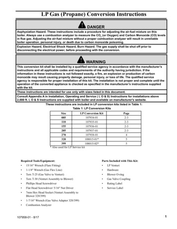
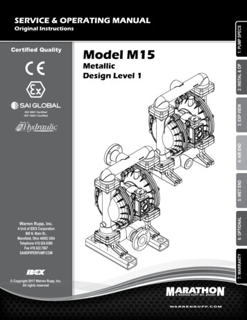
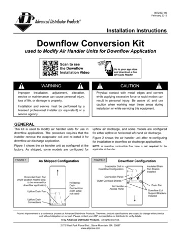
0672327-00February 2015Installation InstructionsDownflow Conversion Kitused to Modify Air Handler Units for Downflow ApplicationScan to seethe DownflowInstallation VideoGo to your app storeand download a freeQR Code ReaderWARNINGCAUTIONImproper installation, adjustment, alteration,service or maintenance can cause personal injury,loss of life, or damage to property.Physical contact with metal edges and cornerswhile applying excessive force or rapid motion canresult in personal injury. Be aware of, and usecaution when working near these areas duringinstallation or while servicing this equipment.Installation and service must be performed by alicensed professional installer (or equivalent) or aservice agency.GENERALThis kit is used to modify air handler units for use indownflow applications. The procedure requires that theinstaller remove the evaporator coil and re-install it fordownflow air discharge application.upflow air discharge, and some models are configuredfor either upflow or horizontal left-hand air discharge.Figure 1 shows the air handler unit as configured at thefactory. As shipped, some models are configured forNOTE: A downflow combustible floor base is not required for theapplicable air handler.FIGURE 1As Shipped ConfigurationFigure 2 shows the air handler unit after re-configuringfor installation in downflow air discharge applications.FIGURE 2Downflow ConfigurationEvaporator Coil inDownflow ConfigurationHorizontal Drain Pan(multi-position models only,to be removed fordownflow application)Upflow Drain PanInsulated DrainPan ShieldsInstalledConnection PanelHorizontalDrainConnections(both sides;not used)Outer Coil Slab ShieldsAir HandlerAccess PanelDrain PanDownflow CoilSupport BracketsInstalledUpflow DrainConnectionsProduct improvement is a continuous process at Advanced Distributor Products. Therefore, product specifications are subject to change without noticeand without obligation on our part. Please contact your ADP representative or distributor to verify details. by Advanced Distributor Products. All rights reserved.2175 West Park Place Blvd., Stone Mountain, GA 30087www.adpnow.com
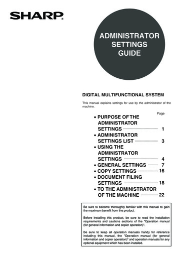
GENERALIMPORTANTIncrease blower speed on all models for downflowoperation. See page 8 for details.WARNINGThe State of California has determined that thisproduct may contain or produce a chemical orchemicals, in very low doses, which may causeserious illness or death. It may also cause cancer,birth defects, or reproductive harm.SHIPPING & PACKING LISTAir Handler Sizes18 & 2425, 30, 3631, 37-60Part uantityInsulated drain pan111AInsulated downflow coil support brackets222BInsulated Inner drain pan drip shields222CNon-insulated outer coil slab shields222DFront and rear insulated air seal plates222ETapping screws (#8 x 1 AB hex washer HD) for downflow coilsupport brackets666FNylon cable ties (5-1/2 long) for outer coil slab shields444GInsulating foam tape for coil suction manifold (16 Long)111HInsulating foam tape for blower housing3N/AN/AIWiring diagram1N/AN/AJPart DescriptionFigure 3PartsFIGURE 3ABCDEDownflowKit PartsHFG2IJ
REMOVING COIL FROM HOUSING1. Remove the connection panel, access panel, and theblower panel. Keep all panels and screws; these will bere-used when reassembling.CAUTION2. Remove the support bar. Keep the bar and 4 screws forlater use.Be certain all power has been disconnected fromthe air handler before beginning work.3. Remove all upflow and horizontal drain pan mountingbrackets (Figures 4 and 5). Discard these brackets.WARNING4. Carefully slide the coil and the horizontal drain panassembly from the air handler cabinet. Discard thehorizontal drain pan.Excessive Weight Hazard - Use two or morepeople when moving and installing the unit. Failureto do so can result in back or other type of injury.5. Remove the rear coil support bracket (Figure 6); discard.FIGURE 4Remove Upflow Drain PanMounting BracketFIGURE 5Remove Horizontal and Upflow DrainPan Mounting Brackets(18 through 30, and 36)(31, and 37 through 60)Remove BracketsSecuring BothDrain Pans to UnitRemove BracketSecuring UpflowDrain Pan to UnitFIGURE 6Remove Rear Coil Bracket3
MODIFYING INDOOR COIL1. Remove 4 screws attaching coil to drain pan (Figure 7).4. Install both outer coil slab shields (Part D, two each)using the provided tie-wraps (Part G, four each) (Figure9) and secure to return bends on both ends. Ensure theshields are within 1/4” from the drain pan.2. Remove the drain pan from the coil and replace it withthe kit-provided insulated drain pan (Part A). Reinstallthe 4 screws.3. Working from the bottom of the coil, install providedinsulated drain pan drip shields (Part C, two each) asillustrated in Figure 8. Be sure each is inserted snuglybetween the drain pan and slab.FIGURE 7Remove Drain PanFIGURE 8Insulated Drain Pan Drip ShieldsFIGURE 9Installing Outer Coil Slab ShieldsRemove the Four Screws Securing the Coil to the Drain PanFRONTBACK4
MODIFYING INDOOR COIL (CONT.)5. Wrap the coil suction manifold and TXV bulb with theprovided insulating foam tape (Part H) to preventcondensate from dripping or blow off the manifold, asshown in Figure 10.FIGURE 10A.NOTE: Failure to install all shields (steps 3 and 4), or the adhesiveback insulating foam (step 5) can result in condensate blow-off andsubsequent damage to the building and its contents.Insulating Coil Suction ManifoldInsert insulating foam tape behind suction manifold asexampled below.B. Remove backing from insulating foam tape to expose adhesiveside as exampled below.C. Fold insulating foam tape over front of the suction manifoldas exampled below.5
MODIFYING AIR HANDLER HOUSING1. Turn housing upside down.4. Using the two insulated coil support brackets (Part B andsix #8-18 x 1” screws (Part F) provided in the downflowkit, install the coil supports brackets to the inner sides ofthe cabinet (Figures 13 and 14).2. Reinstall the support bar using 4 screws (Figure 11)3. Sizes 18 & 24 Units Only: Use three strips of theprovided insulated tape (Part I) and attach to exposedside of the blower housing (Figure 12). This is requiredonly for these sizes to prevent sweating in downflow.5. Position the front and rear insulated air seals (part E)onto the downflow coil support brackets (Figure 15). Besure the seals seat against the back and front of the airhandler and that the front will seat against the accesspanel when reinstalled.NOTE: Removing the blower housing to perform this task isoptional.NOTE: If the insulated tape covers the wiring diagram, anadditional wiring diagram is included in the kit,FIGURE 11Installing Support BarFIGURE 126Blower Housing Insulated(Sizes 18 & 24)
MODIFYING AIR HANDLER HOUSING (CONT.)FIGURE 13Installing Insulated Coil SupportFIGURE 15Air Seals InstalledFIGURE 14Both Coil Support Brackets InstalledREINSTALLING IN DOWNFLOW CONFIGURATIONFIGURE 161. Install evaporator coil with insulated drain pan assemblyon the downflow coil support brackets.2. Re-install the connection panel making sure that theopenings are properly aligned with the refrigerant lines.3. Re-install and fasten the blower panel in the invertedposition.4. Re-install and fasten the access panel.5. Size 18 & 24 units only: Affix the provided wiringdiagram (Part J) to the exterior of the unit access panel.6. Install converted air handler onto floor opening. Applysealant as required.7. Install air filter.7Installing Coil
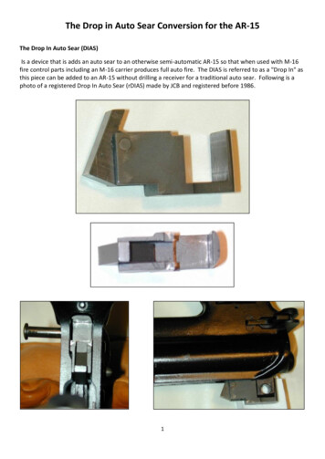
REINSTALLING IN DOWNFLOW CONFIGURATION (CONT.)Downflow ConfigurationFIGURE 17Access Panel RemovedInsulated Downflow Coil SupportWrap the Suction Manifoldwith Insulating Foam Tapeto Prevent Condensationfrom FormingInsulated Front Air SealInsulated RearAir SealOuter Coil Slab ShieldsInsulated DownflowCoil Support#8-18x1 Screws(3 Each Side)Blower PanelFactory-InsulatedDrain Pan Drip ShieldsEvaporator Coil inDownflow ConfigurationSupply (Discharge) FlangePlenumCHANGE BLOWER SPEEDIMPORTANTWARNINGIncrease blower speed on all models for downflowoperation.Electric shock hazard! - Disconnect all powersupplies before servicing.Replace all parts and panels before operating.3-Speed PSC MotorFailure to do so can result in death or electricalshock.1. For downflow operation, use the next highest speedsetting available.2. If set to high speed from the factory, use high speed fordownflow.3. Refer to the air handler installation instructions for detailson how to change the blower speed.5-Speed High Efficiency ECM Motor1. If factory-set speed tap 3 is desirable for your application,use speed tap 5 for downflow.2. If speed tap 2 is desirable for your application, use speedtap 3 in downflow.3. Refer to the air handler installation instructions for detailson how to change the blower speed.8
Air Handler Sizes 18 & 24 25, 30, 36 31, 37-60 Figure 3 PartNumber 165873190 165873191 165873192 Parts Part Description Quantity Quantity Quantity Insulated drain pan 1 1 1 A Insulated downflow coil support brackets 2 2 2 B Insulated Inner drain pan drip shields