Transcription
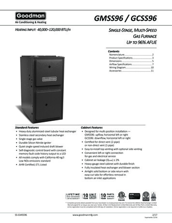
Upflow/ HorizontalDownflow /HorizontalCondensing, Direct VentGas-Fired FurnaceXT 95TUH1B040A9H21A, TUH1B060A9H31A,TUH1B080A9H31A, TUH1C100A9H41A,TUH1D120A9H51ATDH1B040A9H21A, TDH1B065A9H31A,TDH1C085A9H41A, TDH1D110A9H51AHigh Efficiency Single-Stage Fan AssistedCombustion NFLOWTDH1-HDOWNFLOW/HORIZONTALPUB. NO. 22-1859-01
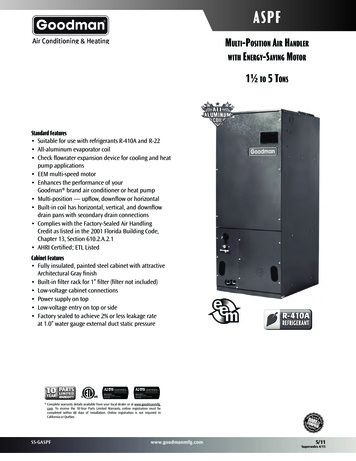
GeneralFeaturesNATURAL GAS MODELSCentral Heating furnace designs arecertified to ANSI Z21.47 / CSA 2.3 forboth natural and L.P. gas. Limit settingand rating data were established andapproved under standard rating conditions using American National Standards Institute standards.SAFE OPERATIONThe Integrated System Control has solidstate devices, which continuously monitorfor presence of flame, when the systemis in the heating mode of operation.Dual solenoid combination gas valveand regulator provide extra safety.QUICK HEATINGDurable, cycle tested, heavy gauge aluminized steel heat exchanger quicklytransfers heat to provide warm conditioned air to the structure. Low energypower vent blower, to increase efficiency and provide a positive dischargeof gas fumes to the outside.BURNERSMultiport Inshot burners will give yearsof quiet and efficient service. All modelscan be converted to L.P. gas withoutchanging burners.INTEGRATED SYSTEM CONTROLExclusively designed operational program provides total control of furnacelimit sensors, blowers, gas valve, flamecontrol and includes self diagnostics forease of service. Also contains connection points for E.A.C./humidifier. 2011 Trane All Rights ReservedFeaturesand BenefitsAIR DELIVERYThe four speed, direct drive blowermotor, has sufficient airflow for mostheating and cooling requirements, willswitch from heating to cooling speedson demand from room thermostat. Theblower door safety switch will prevent orterminate furnace operation when theblower door is removed.STYLINGHeavy gauge steel and “wrap-around”cabinet construction is used in thecabinet with baked-on enamel finish forstrength and beauty. The heat exchanger section of the cabinet is completelylined with foil faced fiberglass insulation.This results in quiet and efficient operation due to the excellent acoustical andinsulating qualities of fiberglass. Built-inbottom pan and alternate bottom, left orright side return air connection provision.FEATURES ANDGENERAL OPERATIONThe XT95 High Efficiency Gas Furnacesemploy a Silicon Nitride Hot SurfaceIgnition system, which eliminates thewaste of a constant burning pilot. Theintegrated system control lights the mainburners upon a demand for heat fromthe room thermostat. Complete frontservice access.a. Low energy power venterb. Vent proving pressure switch.2XT95 Standard Equipment Power supply 115/1/60 Convertible to horizontal with left ofright airflow Type 29-4C stainless steel secondary heat exchanger Inner blower doors Constant torque ECM blower motor Silicon Nitride igniter with adaptiveheat up Accessory hook-up capability –Hum and EAC Quiet induced draft blower Blower door safety switch Dual solenoid combination gas valve ®ulator PVC venting – 1 or 2 pipe vent option Left/right gas connection Selectable cooling fan off delay eliminates need for BAY24X045 time delayrelay Single wire twinning Integrated solid state control with selfdiagnostics 24 volt fuse Manual reset burner box limit Optional extended warranties22-1859-01
ContentsGeneral FeaturesFeatures and BenefitsXT95 Standard EquipmentXT95 Optional EquipmentGeneral 1ATDH1C085A9H41ATDH1D110A9H51APerformance DataElectrical DataField WiringTwinning Field WiringDimensions22-1859-01322245555667777810141516
Features andBenefitsXT95 Optional EquipmentComfort Control, XL803, Programmable 7 Day, 3-Ht, 2-Cl. TCONT803AS32DA [Comfort Control, XR402, Electric, 3-Ht, 2-Cl (Non-programmable).TCONT402AN32DA [For additional comfort control choices, see the product catalog or quick select handbookPropane Conversion Kit.BAYLPKT210B [Propane Conversion Kit (stainless steel burners).BAYLPSS210B [Downflow Subbase.BAYBASE205 [Filter Access Door Kit.BAYFLTR206 [Side Filter Rack.BAYFLTR200 [High Altitude Pressure Switch Kit TUH1B040, TDH1B040, TDH1C085. BAYSWT01AHALTA [High Altitude Pressure Switch Kit TUH1B060, TUH1D100, TUH1D120 . BAYSWT04AHALTA [High Altitude Pressure Switch Kit TUH1B080, TUH1C100, TDH1D110 . BAYSWT05AHALTA [High Altitude Pressure Switch Kit TUH1C080 . BAYSWT11AHALTA [High Altitude Pressure Switch Kit TDH1B065 . BAYSWT12AHALTA [Concentric Vent Kit.BAYAIR30AVENTA [Sidewall Vent Termination Kit. BAYVENT200B [Manufactured/Mobile Home Kit. BAYMFGH100A [4]]]]]]]]]]]]]]]22-1859-01
GeneralDataPRODUCT SPECIFICATIONS 1MODELTYPERATINGS 2Input BTUH 3Capacity BTUH (ICS) 3AFUETemp. rise (Min.-Max.) F.BLOWER DRIVE 8Diameter - Width (In.)No. UsedSpeeds (No.)CFM vs. in. w.g.Motor HP 5R.P.M.Volts / Ph / HzCOMBUSTION FAN — TypeDrive - No. SpeedsMotor HP - RPMVolts / Ph / HzFLAFILTER — Furnished?Type RecommendedShipped (No.-Size-Thk.)VENT PIPE DIAMETER - Min (in.)67HEAT EXCHANGERType - Fired- UnfiredGauge (Fired)ORIFICES — MainNat. Gas. Qty. — Drill SizeL.P. Gas Qty. — Drill SizeGAS VALVEPILOT SAFETY DEVICETypeBURNERS — TypeNumberPOWER CONN. — V / Ph / Hz 4Ampacity (In Amps)Max. Overcurrent Protection (Amps)PIPE CONN. SIZE (IN.)DIMENSIONSCrated (In.)WEIGHTShipping (Lbs.) / Net (Lbs.)TUH1B040A9H21AUpflow / HorizontalTUH1B060A9H31AUpflow / HorizontalTUH1B080A9H31AUpflow / Horizontal40,00038,0009530 - 60DIRECT10 x 714See Fan Performance Table1/21075115/1/60CentrifugalDirect - 11/55 - 3000115/1/601.00YesHigh Velocity1 - 17x25 - 1in.2 Round60,00057,0009530 - 60DIRECT10 x 714See Fan Performance Table1/21075115/1/60CentrifugalDirect - 11/15 - 3450115/1/601.75YesHigh Velocity1 - 17x25 - 1in.2 Round80,00076,0009535 - 65DIRECT10 x 814See Fan Performance Table1/21075115/1/60CentrifugalDirect - 11/20 - 3450115/1/600.71YesHigh Velocity1 - 17x25 - 1in.3 RoundAlum. SteelAlum. SteelAlum. Steel2020202 — 452 — 56Redundant - Single Stage3 — 453 — 56Redundant - Single Stage4 — 454 — 56Redundant - Single StageHot Surface IgnitionMultiport Inshot2115/1/609.7151/2HxWxD41-3/4 x 19-1/2 x 30-1/2Hot Surface IgnitionMultiport Inshot3115/1/6010.4151/2HxWxD41-3/4 x 19-1/2 x 30-1/2Hot Surface IgnitionMultiport Inshot4115/1/609.4151/2HxWxD41-3/4 x 19-1/2 x 30-1/2139 / 129150 / 140158 / 1481 Central Furnace heating designs are certified to ANSI Z21.47 / CSA 2.3.2 For U.S. applications, above input ratings (BTUH) are up to 2,000 feet, derate 4% per 1,000 feet for elevations above 2,000 feet above sealevel.For Canadian applications, above input ratings (BTUH) are up to 4,500 feet, derate 4% per 1,000 feet for elevations above 4,500 feet abovesea level.3 Based on U.S. government standard tests.4 The above wiring specifications are in accordance with National Electrical Code; however, installations must comply with local codes.5 Constant torque ECM blower motor6 Refer to the Vent Length Table in the Installer's Guide or the Allowable Vent Length label located on the furnace.7 All TUH1 and TDH1 furnace models have a vent outlet diameter that equals 2".8 4 Speed, direct drive X13 style high efficiency DC motor22-1859-015
GeneralDataPRODUCT SPECIFICATIONS 1MODELTYPERATINGS 2Input BTUH 3Capacity BTUH (ICS) 3AFUETemp. rise (Min.-Max.) F.BLOWER DRIVE 8Diameter - Width (In.)No. UsedSpeeds (No.)CFM vs. in. w.g.Motor HP 5R.P.M.Volts / Ph / HzCOMBUSTION FAN — TypeDrive - No. SpeedsMotor HP - RPMVolts / Ph / HzFLAFILTER — Furnished?Type RecommendedShipped (No.-Size-Thk.)VENT PIPE DIAMETER - Min (in.)67HEAT EXCHANGERType - Fired- UnfiredGauge (Fired)ORIFICES — MainNat. Gas. Qty. — Drill SizeL.P. Gas Qty. — Drill SizeGAS VALVEPILOT SAFETY DEVICETypeBURNERS — TypeNumberPOWER CONN. — V / Ph / Hz 4Ampacity (In Amps)Max. Overcurrent Protection (Amps)PIPE CONN. SIZE (IN.)DIMENSIONSCrated (In.)WEIGHTShipping (Lbs.) / Net (Lbs.)TUH1C100A9H41AUpflow / HorizontalTUH1D120A9H51AUpflow / HorizontalTDH1B040A9H21AUpflow / Horizontal97,00092,1059535 - 65DIRECT11 x 1014See Fan Performance Table3/41100115/1/60CentrifugalDirect - 11/20 - 3450115/1/60.71110,000104,5009540 - 70DIRECT11 x 1014See Fan Performance Table11100115/1/60CentrifugalDirect - 11/20 - 3450115/1/60.71High Velocity1 - 20x25 - 1in.3 RoundHigh Velocity1 - 24x25 - 1in.3 Round40,00038,0009530 - 60DIRECT10 x 714See Fan Performance Table1/21080115/1/60CentrifugalDirect - 11/55 - 3000115/1/601.14YesHigh Velocity1 - 14x20 - 1in.2 RoundAlum. SteelAlum. SteelAlum. Steel2020205 — 455 — 56Redundant - Single Stage6 — 456 — 56Redundant - Single Stage2 — 452 — 56Redundant - Single StageHot Surface IgnitionMultiport Inshot5115/1/6011.4151/2HxWxD41-3/4 x 23 x 30-1/2Hot Surface IgnitionMultiport Inshot6115/1/6014.1201/2HxWxD41-3/4 x 26-1/2 x 30-1/2Hot Surface IgnitionMultiport Inshot2115/1/609.7151/2HxWxD41-3/4 x 19-1/2 x 30-1/2171 / 160205 / 193145 / 135YesYes1 Central Furnace heating designs are certified to ANSI Z21.47 / CSA 2.3.2 For U.S. applications, above input ratings (BTUH) are up to 2,000 feet, derate 4% per 1,000 feet for elevations above 2,000 feet above sealevel.For Canadian applications, above input ratings (BTUH) are up to 4,500 feet, derate 4% per 1,000 feet for elevations above 4,500 feet abovesea level.3 Based on U.S. government standard tests.4 The above wiring specifications are in accordance with National Electrical Code; however, installations must comply with local codes.5 Constant torque ECM blower motor6 Refer to the Vent Length Table in the Installer's Guide or the Allowable Vent Length label located on the furnace.7 All TUH1 and TDH1 furnace models have a vent outlet diameter that equals 2".8 4 Speed, direct drive X13 style high efficiency DC motor622-1859-01
GeneralDataPRODUCT SPECIFICATIONS 1MODELTYPERATINGS 2Input BTUH 3Capacity BTUH (ICS) 3AFUETemp. rise (Min.-Max.) F.BLOWER DRIVE 8Diameter - Width (In.)No. UsedSpeeds (No.)CFM vs. in. w.g.Motor HP 5R.P.M.Volts / Ph / HzCOMBUSTION FAN — TypeDrive - No. SpeedsMotor HP - RPMVolts / Ph / HzFLAFILTER — Furnished?Type RecommendedShipped (No.-Size-Thk.)VENT PIPE DIAMETER - Min (in.)67HEAT EXCHANGERType - Fired- UnfiredGauge (Fired)ORIFICES — MainNat. Gas. Qty. — Drill SizeL.P. Gas Qty. — Drill SizeGAS VALVEPILOT SAFETY DEVICETypeBURNERS — TypeNumberPOWER CONN. — V / Ph / Hz 4Ampacity (In Amps)Max. Overcurrent Protection (Amps)PIPE CONN. SIZE (IN.)DIMENSIONSCrated (In.)WEIGHTShipping (Lbs.) / Net (Lbs.)TDH1B065A9H31AUpflow / HorizontalTDH1C085A9H41ADownflow / HorizontalTDH1D110A9H51BDownflow / Horizontal60,00057,0009525 - 55DIRECT10 x 814See Fan Performance Table3/41075115/1/60CentrifugalDirect - 11/25 - 3200115/1/601.35YesHigh Velocity2 - 14x20 - 1in.2 Round80,00076,0009530 - 60DIRECT11 x 1014See Fan Performance Table3/41075115/1/60CentrifugalDirect - 11/20 - 3450115/1/60.71YesHigh Velocity2 - 16x20 - 1in.2.5 Round110,000104,5009535 - 65DIRECT11 x 1014See Fan Performance Table11075115/1/60CentrifugalDirect - 11/20 - 3450115/1/60.71YesHigh Velocity2 - 16x20 - 1in.2.5 RoundAlum. SteelAlum. SteelAlum. Steel2020204 — 484 — 56Redundant - Single Stage5 — 485 — 56Redundant - Single Stage6 — 486 — 56Redundant - Single StageHot Surface IgnitionMultiport Inshot4115/1/6010.0151/2HxWxD41-3/4 x 19-1/2 x 30-1/2Hot Surface IgnitionMultiport Inshot5115/1/6011.4151/2HxWxD41-3/4 x 23 x 30-1/2Hot Surface IgnitionMultiport Inshot6115/1/6014.1201/2HxWxD41-3/4 x 26-1/2 x 30-1/2158 / 148171 / 160205 / 1931 Central Furnace heating designs are certified to ANSI Z21.47 / CSA 2.3.2 For U.S. applications, above input ratings (BTUH) are up to 2,000 feet, derate 4% per 1,000 feet for elevations above 2,000 feet above sealevel.For Canadian applications, above input ratings (BTUH) are up to 4,500 feet, derate 4% per 1,000 feet for elevations above 4,500 feet abovesea level.3 Based on U.S. government standard tests.4 The above wiring specifications are in accordance with National Electrical Code; however, installations must comply with local codes.5 Constant torque ECM blower motor6 Refer to the Vent Length Table in the Installer's Guide or the Allowable Vent Length label located on the furnace.7 All TUH1 and TDH1 furnace models have a vent outlet diameter that equals 2".8 4 Speed, direct drive X13 style high efficiency DC motor22-1859-017
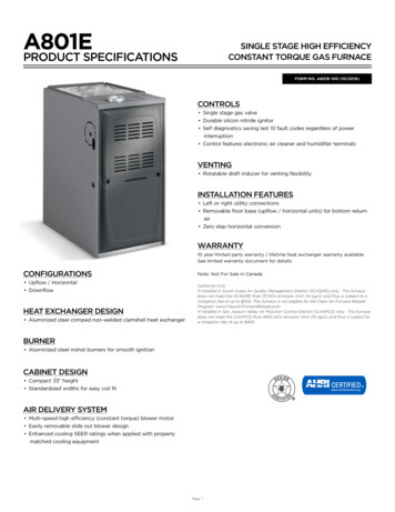
H1B080A9H31ATUH1C100A9H41ATUH1D120A9H51AFURNACE AIRFLOW (CFM) VS. STATIC PRESSURE (ins.w.g.)SPEED TAP0.10.20.30.40.50.64 - HIGH - Black1159113111021077105210223 - MED-HIGH - Blue9389108818518207862 - MED-LOW - Yellow8448147837507176811 - LOW - Red**7727326916566215814 - HIGH - Black1402136213181267121411573 - MED-HIGH - Blue**1199117411491127109910752 - MED-LOW - Yellow110410801053103110029801 - LOW - Red8348087707507126774 - HIGH - Black1328130412771253122411823 - MED-HIGH - Blue**1519149314641422136813062 - MED-LOW - Yellow1072103910159919569281 - LOW - Red8107827597297036684 - HIGH - Black1586155215171477144314103 - MED-HIGH - Blue**1893185818261793175917242 - MED-LOW - Yellow1364132012821241120511671 - LOW - Red1107106010039599198634 - HIGH - Black2141210820762041200919763 - MED-HIGH - Blue**2072203820071975193819102 - MED-LOW - Yellow1886185318161785175417181 - LOW - 695910548285821289158210457301826179716191358** HEATING SPEED TAPCFM VS. TEMPERATURE RISEMODELCFM (CUBIC FEET PER MINUTE)600 700 800 900 1000 1100 1200 1300 1400 1500 1600 1700 1800 1900 2000 2100 2200 2300TUH1B040A9H21A 59 50 44 1A59TUH1D120A9H51A8464422-1859-01
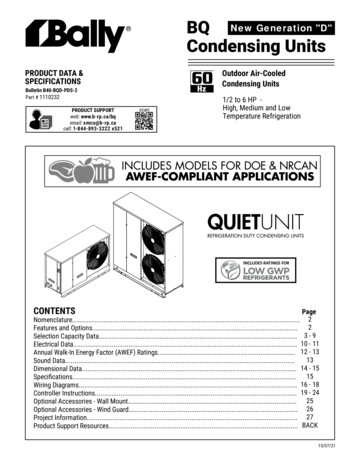
PerformanceDataFURNACE AIRFLOW (CFM) VS. STATIC PRESSURE (ins.w.g.)MODELSPEED TAP0.1TDH1B040A9H21A4 - HIGH - Black3 - MED-HIGH - Blue2 - MED-LOW - Yellow**1 - LOW - Red0.20.30.40.50.60.70.80.91156 1128935 859835 803752 9H31A4 - HIGH - Black3 - MED-HIGH - Blue**2 - MED-LOW - Yellow1 - LOW - Red1455 14041375 13501099 1076838 8TDH1C085A9H41A4 - HIGH - Black3 - MED-HIGH - Blue**2 - MED-LOW - Yellow1 - LOW - 0A9H51A4 - HIGH - Black3 - MED-HIGH - Blue**2 - MED-LOW - Yellow1 - LOW - 72116491546136216301579150513171543149914681282** HEATING SPEED TAPCFM VS. TEMPERATURE ACFM (CUBIC FEET PER MINUTE)600 700 800 900 1000 1100 1200 1300 1400 1500 1600 1700 1800 1900 2000 2100 2200 54TDH1D110A9H51A22-1859-019514846
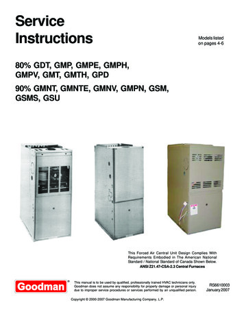
ElectricalDataTUH1-H WiringFrom Dwg. D3424911022-1859-01
ElectricalDataTUH1-H SchematicFrom Dwg. D34249122-1859-0111
ElectricalDataTDH1-H WiringFrom Dwg. D342800P011222-1859-01
ElectricalDataTDH1-H SchematicFrom Dwg. D342800P0122-1859-0113
FieldWiringSEENOTE 7FIELD WIRING DIAGRAM FOR 1 STAGE FURNACE1 STAGE HEATINGUSING A 1 STAGE HEATING THERMOSTATNO COOLINGFURNACETWINB/CSEENOTE 6TO 115 V 1 PH.,60 HZ., POWERSUPPLY PERLOCAL CODESB/CHUM SEENOTE 5EAC SEENOTE 5From Dwg. B341437 Rev. 1FIELD WIRING DIAGRAM FOR 1 STAGE FURNACE1 STAGE HEATING, 1 STAGE COOLINGUSING A 1 STAGE HEATING, 1 STAGE COOLING THERMOSTAT(OUTDOOR SECTION WITHOUT TRANSFORMER)FURNACEOUTDOOR UNIT(NO TRANSFORMER)SEENOTE 6B/CSEENOTE 8B/CTO 115 V 1 PH.,60 HZ., POWERSUPPLY PERLOCAL CODESHUM SEENOTE 5EAC SEENOTE 514From drawing B340388 Rv 222-1859-01
TwinningField Wiring1 STAGE HEATONLYTHERMOSTAT(WITH FAN SWITCH)TWINNING CONNECTION DIAGRAMFOR TWINNING 1 STAGE FURNACES WITHSINGLE WIRE TWINNING FEATURE1 STAGE HEATING ONLY THERMOSTATFURNACE NO. 2FURNACE NO. 1BLOWER OPERATION OFUNIT NO. 2 IS SYNCRONIZEDWITH UNIT NO. 1 VIA SIGNALSFROM TWIN CONNECTION.TWINTWINSEE NOTE 4ISOLATION RELAY(FIELD SUPPLIED)SEE NOTE 4R1R1ISOLATION RELAYSEE NOTE 4B/CSEE NOTE 3B/CB/CFrom Dwg. 21B341422 Rev. 3OUTDOOR UNIT(WITH TRANSFORMER)1 STAGEHEATING / COOLINGTHERMOSTATTWINNING CONNECTION DIAGRAMFOR TWINNING 1 STAGE FURNACES WITHSINGLE WIRE TWINNING FEATURE1 STAGE HEAT / 1 STAGE COOL THERMOSTATFURNACE NO. 2FURNACE NO. 1BLOWER OPERATION OFUNIT NO. 2 IS SYNCRONIZEDWITH UNIT NO. 1 VIA SIGNALSFROM TWIN CONNECTION.TWINTWINRCISOLATION RELAY(FIELD SUPPLIED)SEE NOTE 3SEE NOTE 4OUTDOOR UNIT(NO TRANSFORMER)R1ISOLATION RELAYSEE NOTE 4B/CSEE NOTE 5R1B/CB/CISOLATION RELAY(FIELD SUPPLIED)SEE NOTE 422-1859-0115From Dwg. 21B341423 Rev. 2
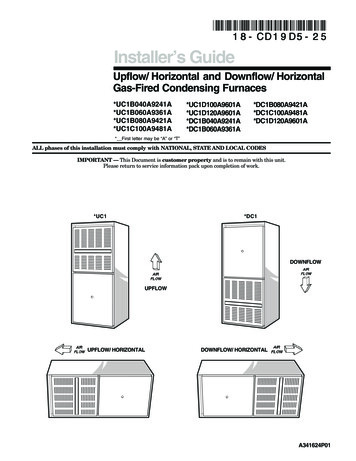
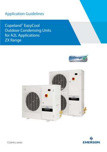
(ALL DIMENSIONS ARE IN INCHES)TUH1-H OUTLINE DRAWING16From Dwg. 21C341884NOTES:1. *UH1B080A9H31, *UH1C100A9H41, & *UH1D120A9H51REQUIRE 3” DIAMETER VENT PIPE.2. DIAMETER OF VENT PIPE MAY BE LIMITED TO 2-1/2”OR 3” ON SOME MODELS AT DIFFERENT ALTITUDES.REFER TO THE VENT LENGTH TABLE FOR PROPERAPPLICATION.Dimensions22-1859-01
(ALL DIMENSIONS ARE IN INCHES)TDH1-H OUTLINE DRAWINGFrom Dwg. 21C341885Dimensions22-1859-0117
LiteratureOrder Number22-1859-01Trane6200 Troup HighwayTyler, TX 75707www.trane.comFile Number22-1859-01SupersedesNewDate11/11Trane has a policy of continuous product and product data improvement and it reserves the right to changedesign and specifications without notice.
6 22-1859-01 General Data TUH1D120A9H51A Upflow/Horizontal 110,000 104,500 95 40 - 70 DIRECT 11 x 10 1 4 See Fan Performance Table 1 1100 115/1/60 Centrifugal