Transcription
Downflow, Direct Vent (Sealed Combustion)Forced Air Gas and Oil FurnacesOwners Manual/Installation InstructionsSeries M1B, M1G, M1M and M1SFor installation in:1. Manufactured Homes2. Recreational Vehicles, Park Models,Manufactured Buildings3. Modular Homes/Buildings! WARNING:If the information in this manual is notfollowed exactly, a fire or explosionmay result causing property damage,personal injury or loss of life.– Do not store or use gasoline or otherflammable vapors and liquids in thevicinity of this or any other appliance.– WHAT TO DO IF YOU SMELL GAS Do not try to light any appliance. Do not touch any electrical switch;do not use any phone in your building. Immediately call your gas supplierfrom a neighbor’s phone. Follow thegas supplier’s instructions. If you cannot reach your gas supplier, call the fire department.– Installation and service must be performed by a qualified installer, service agency or the gas supplier.! WARNING:! WARNING:Should overheating occur, or the gassupply fail to shut off, shut off themanual gas valve to the appliancebefore shutting off the electrical supply.Improper installation, adjustment, alteration, service or maintenance cancause injury or property damage. Refer to this manual. For assistance oradditional information consult a qualified installer, service agency or thegas supplier.LEAVE THESE INSTRUCTIONS WITH THE HOMEOWNER.
TABLE OF CONTENTS1. SPECIFICATIONS . 32. OWNERS INFORMATION . 33. MANUFACTURER WARRANTY, OWNER RESPONSIBILITY . 34. INSTALLATION STANDARDS . 55. UNIT LOCATION . 66. MINIMUM CLEARANCES . 67. RETURN AIR PROVISIONS . 68. AIR DISTRIBUTION SYSTEMS . 89. ROOF JACK SELECTION . 810. DUCT CONNECTOR SELECTION . 911. INSTALLATION . 1112. INSTALLATION OF TRANSIT-MODE VENTING SYSTEM . 1413. ELECTRICAL WIRING . 1514. FUEL PIPING . 1615. FLUE GAS SAMPLING . 1916. LIGHTING AND FURNACE SHUT DOWN . 2017. SERVICE GUIDE . 2518. MAINTENANCE . 3019. OPTIONAL ACCESSORIES . 3120. WIRING DIAGRAMS . 34-3921. EQUIVALENT ORIFICE SIZES AT HIGH ALTITUDES . 40M 1 M B - 056 A - B WApplicationM-Manufactured HomeFurnace SeriesFuel, Type of CombustionG-Gas, Direct Vent, Pilot BurnerNatural or Forced DraftM-Gas, Direct Vent, HSI,Forced DraftB-Gas, Direct Vent, Gun BurnerS-Oil, Direct Vent, Gun BurnerCabinet DimensionsA - 56" x 19-3/4" x 23-3/4”B - w/Coil Cavity,76" x 19-3/4" x 23-3/4"Electrical CodeA - 1PH, 60 Hz, 120 VACComfort ModelH - HeatingA - Heating, A/C ReadyB - A/C Ready, 3 TonC - A/C Ready, 4 TonD - A/C Ready, 5 TonHeating CapacityInput, BTUH (000’)Table 1. Model Identification2Door ColorW - WhiteG - Gray
! WARNING:Do not use this appliance if any parthas been submerged under water.Immediately call a qualified servicetechnician to inspect the applianceand to replace any part of the controlsystem and any gas control that hasbeen submerged underwater.NOTICE TO INSTALLERInstaller is advised to follow carefully all instructions and warnings in this manual to insuremaximum performance, safety, and operatingefficiency of these appliances. Improper installation may create hazardous conditions, andwill void the appliance warranty.1.SPECIFICATIONSGeneral DescriptionM1 Series gas and oil furnaces are listed directvent (sealed combustion), downflow heatingappliances for manufactured (mobile) homes,recreational vehicles, and for use in residential/modular/commercial construction. The furnacemust be located so that venting can be properlyachieved.Air conditioning may be added to structures withM1 series furnaces using Platinum series airconditioning or conventional units. This Installation Instruction manual includes special requirements for incorporation of air conditioningequipment to the M1 series of furnaces.Multi-speed blower assemblies as shown inTable 3 have been certified for field installationin M1 Series furnaces. An air conditioner can beeasily field installed with M1GH Series furnacesif used in conjunction with certified 2-wire relaybox, p/n 903092A or 4/5 wire relay box 902898A.2.OWNER INFORMATIONABOUT YOUR CENTRALFURNACE SYSTEMNORDYNE has been involved in the design ofproducts for the manufactured home industrysince the first manufactured home or trailer wasbuilt.NORDYNE originated the sealed combustionsystem, which separates the furnace combustion system from the living area of the home,now a standard for the manufactured homeindustry.NORDYNE engineers developed the first central heating system and the first central airconditioner for manufactured homes.NORDYNE is dedicated to bringing to its customers the finest heating and cooling comfortpossible. NORDYNE constantly seeks to further refine its products to continuously provideexceptional comfort.Follow the instructions in this booklet carefullyand this appliance will provide many years ofsuperior performance.If you wish to cool your home automatically witha central air conditioning system investigate theexcellent NORDYNE cooling systems available from your heating and cooling contractor.These systems are designed to work best withyour NORDYNE furnace and have been carefully engineered to deliver optimum performancewhen mated with NORDYNE manufacturedhome furnaces.NORDYNE also offers water heaters, fireplaces and ventilating systems specifically designed for manufactured housing applications.Check with your manufactured home retailer,your heating and cooling contractor or yourdistributor for information. Write directly to thefactory (PO Box 46911, St. Louis, MO 63146)if you are not able to locate a source forNORDYNE manufactured housing products inyour area.3.MANUFACTURER WARRANTY,OWNER’S RESPONSIBILITIESIt is the sole responsibility of the homeowner tomake certain the gas furnace has been correctly set up and converted to the proper fuel(L.P. gas or Natural gas) and adjusted to operate properly. All gas furnaces are manufactured for Natural gas and must be field converted when using L.P. gas.A warranty certificate with full details is includedwith these instructions. However, NORDYNEwill not be responsible for any costs found3
necessary to correct problems due to impropersetup, improper installation, furnace adjustments, improper operating procedure on thepart of the user, etc.Some specific examples of service calls whichcannot be included in warranty payments are:1. Converting the furnace to use another typeof gas.2. Repairing duct work in the home found to befaulty.3. Correcting wiring problems in the electricalcircuit supplying the furnace.4. Resetting circuit breakers, blown fuses orother switches.FurnaceInputOutputOrifice NoModel No MBtu/h MBtu/h Nat.LPM1GH 05656452945M1GB 05656452945M1GC 05656452945M1GD 05656452945M1GH 07070572442M1GB 07070572442M1GC 07070572442M1GD 07070572442M1GH 07777622140M1GB 07777622140M1GC 07777622140M1GD 07777622140M1GH 09090721736M1GB 09090721736M1GC 09090721736M1GD 09090721736M1MA 05656462945M1MB 05656462945M1MC 05656462945M1MD 05656462945M1MA 07070572442M1MB 07070572442M1MC 07070572442M1MD 07070572442M1MB 07777622140M1MC 07777622140M1MD 07777622140M1MB 09090721736M1MC 09090721736M1MD 09090721736M1BA 06666532643M1BC 06666532643M1BB 08686681837M1BC 08686681837M1SA 0666654.50 GphM1SC 0666654.50 GphM1SB 0868671.65 GphM1SC 0868671.65 GphE.S.P.In .30.30.240.30.30.3Electrical Supply - 120 volts, 60HZ, 1 Ph.Fuse or Breaker - 15 ampsTemperature Rise - 45 to 75 FHigh Altitude - See Table 11. For CanadianHigh Altitude (2,000’ to 4,500’), reduce thegas manifold pressure to 3.0” W.C. fornatural gas and to 8” W.C. for LP gas.5. Correcting problems due to improper gassupply pressure to the furnace.6. Providing instructional training on how tolight and operate the furnace.7. Furnace problems caused by installation ofan air conditioner, heat pump or other aircomfort devices.8. Adding a Roof Jack extension because ofunusual wind and/or snow conditions.9. Revising installation of the furnace flue assembly (Roof Jack).10. Adjusting or calibrating of thermostat.11. Any construction debris which falls into xxxxxxxxxxBurner ModelAF-10 NozzleSpray Angle80 AA/C 4342½434Thermostat Circuit - 24 volts, 60HZ, 30 vacNormal Anticipator Setting - 0.4Manifold Pressure - Natural Gas: 3.5” w.c.LP Gas: 10” w.c.*Blower capacity only - needs relay box for ACTable 2. M1 Furnace 3/41/41/23/41/51/21/41/21/51/21/41/2
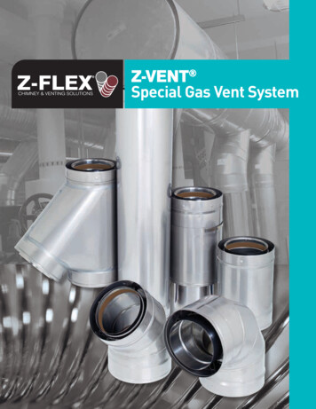
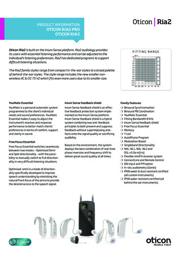
Part No.903773903413903414Blower / Motor AssemblyBlower WheelMotor-Hp10 x 81/411 x 81/211 x 83/4A/C CapacityTon2, 2½ & 32, 2½, 3 & 42, 2½, 3, 4 & 5Table 3. Field Installation Blower AssembliesCarefully review these responsibilities with yourmanufactured housing dealer, service company or gas supplier so there will be no misunderstanding at a later time.! CAUTION: Never attempt to alter or modify thisfurnace or any of its components. Never attempt to repair damaged orinoperable components. Such actioncould cause unsafe operation, explosion, fire and/or asphyxiation. If a malfunction has occurred, or ifyou feel that the furnace is not operating as it should, contact a qualifiedservice agency or gas utility for assistance.4.INSTALLATION STANDARDSInstaller shall be familiar with and comply with allcodes and regulations applicable to the installation of these heating appliances and relatedequipment. In lieu of local codes, the installationshall be in accordance with the current provisions of one or more of the following standards.6" (152 mm)Top Clearance0" SideClearanceto FurnaceCabinetProvide removableaccess panel abovefurnace door frame toaccess roof jack1(457 8"mm)NearestWall orPartitionFigure 2. Alcove Installation6" (152 mm)Top Clearance0" SideClearanceto FurnaceCabinetProvide min. 235sq. in. (1516 cm 2 )open free area infront or side wallorIn closetdoorlocatedat top,centeror bottom(1526"mm)CLOSET DOORFigure 3. Closet Installation“A”- 56"6" (152 mm)Top ClearanceProvide min. 250sq. in. (1613 cm 2 )open free area infront or side wall“B”- 76"“A” Modelw/o Coil CabinetA fullylouvereddoor maybe used0" SideClearanceto FurnaceCabinet“B” Modelw/Coil Cabinet1(25 "mm)23 3/4"19 3/4"Figure 1. Overall DimensionsCLOSET DOORFigure 4. Special 1” Clearance5
a. Federal Manufactured Home Constructions& Safety Standard (H.U.D. Title 24, Part3280.707[a][2])b. American National Standard (ANSI-119.2/NFPA-501C) for all recreational vehicle installations.c. American National Standard (ANSI-Z223.1/NFPA-54) and/or CAN/CGA B149 for all gasfired furnace models.d. American National Standard (ANSI-Z95.1/NFPA-31) and/or CSA B139 for all oil-firedfurnace models.e. American National Standard (ANSI-C1/NFPA-70) and/or CSA 22.1 Canadian Electric Code Part 1 for all electrical field wiring.f. Units have been investigated under standards UL 307A & B, ANZI 21.47a — CAN/2.3a - 1995, and CSA B140.10.to the air filter, blower assembly, burner assembly, controls, and vent connections.a. Alcove installations (see Figure 2): minimum18" clearance at front of furnace shall beprovided for future servicing. A removableaccess panel should be installed betweentop of the furnace door frame and the ceiling.b. Closet installations must use a louvered doorhaving a minimum free area of 235 sq. in.when located 6" from furnace (See Figure 3)or 390 sq. in. for 5 ton ready M1 furnaces. Forspecial clearance between 1" and 6", requirements are a louvered door with a minimum of 250 sq. in. free area, with the openings in the closet door directly in line with thelouvered openings in the furnace door . A fullylouvered closet door may be used (SeeFigure 4).5.UNIT LOCATIONThe furnace shall be appropriately located tothe supply and return air distribution system.(See “AIR DISTRIBUTION”, Page 8) Sides andback of the furnace may be enclosed by wallframing. (See “Minimum Clearances,” Table 4,and Figures 2 through 5.)The furnace installation is only intended for freeair return through the furnace door louvers. DONOT connect a ducted return air system directly to the furnace. Improper installation maycreate a hazard and damage equipment, as wellas void all warranties.Furnace may be installed on combustible flooring when using NORDYNE Duct Connectors(see Section 10).6.MINIMUM CLEARANCESThis heating appliance must be installed withclearances not less than the minimums shownin Table 4. This heating appliance must beinstalled with ample clearance for easy accessALL MODELSFrontBackSidesRoof JackTopTop and Sides of DuctBottom of DuctB CabinetA Cabinet (w/ coil box)A Cabinet (w/o coil box)CLOSET6"0"0"0"6"0"ALCOVE18"0"0"0"6"0"U.S.A. home manufacturers shall comply withall of the following conditions to have acceptablereturn air systems for closet installed forced airheating appliances:! CAUTION:HAZARD OF ASPHYXIATION: Negative pressure inside the closet, withcloset door closed and the furnaceblower operating on high speed, shallbe no more negative than minus 0.05inch water column.a. Regardless of the location, the return airopening into the closet shall not be less thanspecified in the appliance’s listing.A Single trunk ductDual trunk ductB w/crossover connectorC0"0"1/4"Table 4. Minimum Clearances67.RETURN AIR PROVISIONSTransition ductw/branches0"0"1/4"Figure 5. Non-PlatinumSupply Duct System
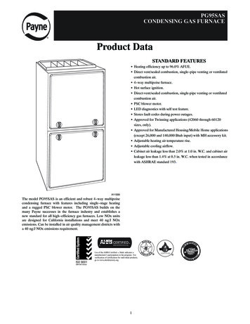
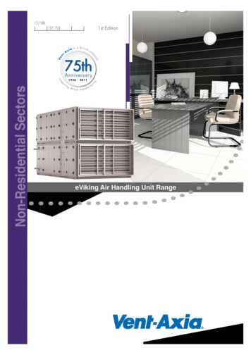
b. Means shall be provided to prevent inadvertent closure by a flat object placed over thereturn air opening when it is located in the floorof the closet (versus the vertical front or sidewall).c. The cross-sectional area of the return ductsystem leading into the closet, when locatedin the floor or ceiling shall not be less than 235square inches (or 390 square inches for 5 tonready M1 Furnaces).d. The total free area of openings in the floor orceiling registers serving the return air ductsystem must be at least 352 sq. in. At leastone register should be located where it is notlikely to be covered by carpeting, boxes andother objects.e. Materials located in the return duct systemmust have a flame spread classification of200 or less. This includes a closet door if thefurnace is in a closet.f. Noncombustible pans having 1" upturnedflanges are located beneath openings in afloor duct system.g. Wiring materials located in the return ductsystem shall conform to Articles 300-22 ofthe National Electrical Code (ANSI C1/NFPA70).h. Gas piping is not run in or through the returnduct system.ROOF JACKSLANT DECKFLASHINGPITCHEDROOF"X" (SEE TABLE 1)CEILINGCAVITY"A"ROOFOPENINGFlue PipeCEILINGCombustionAir Pipe"B"Furnace56" or 76"Approx. LengthModel NumberBelow Flashing(F,S)AW(T)1523-(0,2,4)(A,S)15" - 23"(F,S)AW(T)2135-(0,2,4)(A,S)21" - 35"(F,S)AW(T)2747-(0,2,4)(A,S)27" - 47"(F,S)AW(T)3563-(0,2,4)(A,S)35" - 63"(F,S)AW(T)5195-(0,2,4)(A,S)51" - 95"S AWF FLAT FLASHINGS SLANT FLASHINGT27 47 - 2TYPE:BLANK NON-TRANSITT TRANSIT MODEROOF JACKPITCHEDROOFSFLUE STEEL TYPEA ALUMINIZEDS STAINLESSMIN. ADJ.LENGTHAW ALL WEATHERFigure 6. Roof Jack AssembliesFLASHINGPITCH/12" RISE0 FLAT2 2.5/124 4/12MAX. ADJ.LENGTH"X" (SEE TABLE 6)CEILING CAVITYCEILINGAll Weather Roof Jack AssembliesMODELNUMBERFO1323 -5FO2343 -5SO1835 -5SO2447 -5SO3263 -5SO4895 -5SOT2442 -5SOT2745 -5SOT4581 -5FOT2846 -5SOTAPPROX. ADJ.LENGTHS*BELOW FLASHING13" - 23"23" - 43"18" - 35"24" - 47"32" -63"48" - 95"24" - 42"27" - 45"45" - 81"28" - 46"27S SLAT FLASHING T TRANSITMODEF FLAT FLASHINGTYPEO TYPE; STANDARDH HIGH WINDA ARCTIC ROOF JACKSLANT DECKFLASHINGROOF OPENINGCEILING OPENINGFigure 7. Example of Flat Jackwith FlashingROOF JACK WITH2 1 2 /12 SLANTFLASHING45 -55 5" FLUE DIA.2 1 2 /12SLANT DECK5/12 ROOF SLOPEMAX. ADJ.LENGTHMIN. ADJ.LENGTHTable 5. Roof Jack AssembliesFigure 8. Example of 2½/12 Slant Jackwith Flashing7
i. Test the negative pressure in the closet withthe air-circulating fan operating at high speedand the closet closed. The negativepressure is to be no more negative thanminus 0.05 inch water column.j. For floor return systems, the manufacturedhome manufacturer shall affix a prominentmarking on or near the appliance where it canbe easily read when the closet door is open.The marking shall read:k. Air conditioning systems may require moreduct register and open louver area to obtain necessary airflow. Use NORDYNE’scertiduct program to determine proper ductsize for A/C.8.AIR DISTRIBUTION SYSTEMSFor proper air distribution, the supply ductsystem must be designed so that the staticpressure measured external to the furnacedoes not exceed the listed static pressurerating shown on the furnace rating plate.b. F Flat Flashing; flexes from 0/12 to 1/12 roofslope.c. S Slant Flashing. 2.5/12 Slope flexes from 1/12 to 4/12 roof slope, 4/12 flexes from 3/12to 5/12.d. Stainless steel roof jacks are available.e. If the roof jack crown is covered or blockedwith snow, the furnace will not operate properly. If the home is located in regions wheresnow accumulation exceeds 7” (HUDsnowload zones) use an external roof jackextension p/n 901937.f. M1 furnaces may be used with roof jacks astall as 170” (except M1M 056 & M1B 066models, which are limited to 120”). An internalroof jack extension (p/n 901935 - 10”, p/n903107 - 18”) can be used to increase roofjack height. All connections inside the homemust be made below the ceiling.These extensions are available as optionalaccessories and may be purchased throughyour NORDYNE distributor.Location, size, and number of registers shouldbe selected on the basis of best air distributionand floor plan of the home.IF ROOF PITCH IS:! CAUTION:HAZARD OF ASPHYXIATION: Do notcover or restrict return air opening.9.ROOF JACK SELECTIONNote: Install only Roof Jack Assemblies listedin Table 5 on this heating appliance.a. Determine depth of ceiling cavity from centerof roof opening to center of ceiling opening.(See Dimension “A” in Figure 6.)b. Determine ceiling height and subtract heightof furnace. (See Dimension “B” in Figure 6.)c. Add dimensions A B (and X from Table 6 andFigure 7 if slant deck flashing is used). Thetotal length of (A B X) must be within theminimum and maximum range of one of theRoof Jacks listed in Table 5.APPLICATION NOTES:a. FAW, FAWT, SAW and SAWT Series RoofJacks with a 5" diameter inner vent pipe maybe used with all models of M1 Series gas andoil furnaces.USE SLANT DECKFLASHING NO."X" FACTOR IS:"F Series Roof Jack2" in 12"903893 (2.5/12)2-1/8"2-1/2" in 12"903893 (2.5/12)2-1/2"3" in 12"903894 (3/12)2-7/8"3-1/2" in 12"903894 (3/12)3-1/4"4" in 12"903895 (4/12)3-5/8""S" Series Roof Jack (2.5/12 Pitch only)4-1/2" in 12"5" in 12"5-1/2" in 12"6" in 12"6-1/2" in 12"903895 (2.5/12)903895 (2.5/12)903894 (3/12)903894 (3/12)903895 (4/12)2-1/8"2-1/2"2-7/8"3-1/4"3-5/8"Optional Deck Flashings for Flat and 2.5/12 PitchRoof Jacks.(4/12 Pitch Roof Jacks not applicable.)Table 6. Slant Deck FlashingsIf "X" (Floor Cavity) is:EnglishMetric 012-1/4"311Use Duct ConnectorModel Part Number:Finger TabScrew 11901991904012901992904013901993904014Table 7. Floor Cavity Sizes8
10. DUCT CONNECTOR SELECTIONPLATINUM SERIESa. For Platinum ready construction usethe 14” round duct connector, p/n:903896.NON-PLATINUM SERIESb. Select appropriate model from Table 7which matches X-dimension of the floorcavity. To maximize air delivery, remove reducer “C” (see Figure 11) toobtain the largest open area that will fitthe duct/floor construction. Screw downduct connector opening to duct withoutreducer is 13” x 13”. With reducer it is13” x 10-1/8”.a. Determine depth of floor cavity fromsurface of floor to top of supply air duct(See Figure 9).FLOOR CAVITY(depth equal to "X" in Figure 11 and Table 7)xSUPPLY AIR DUCTFigure 9.19”10 1/4"19"13 1/4"Top ViewofFinger TabDuctConnectorFigure 10.*OPENING TO DUCTREDUCER*FELT-SEALWITH PLATE (C) REMOVEDOPENING BECOMES13-1/4” x 13-1/4”CXSPACERSSEETABLE 7*INDICATES FINGER TAB DUCT CONNECTOR ONLYFigure 11.9
CLCEILING AND ROOFOPENINGS13-1/2"CLREARALLWSIDEWALLALT. FUELLINE HOLES10"CLFLOOROPENINGFUEL LINEHOLECL23 -1/4"Figure 12. Closet or Alcove20"14-1/2"CL2-3/4"CLFLOOR CUT-OUTFOR OPTIONALCOOLING COILFOR NON-PLATINUMCL SERIES UNITSFUEL-LINE3/4"2"10"12-7/8"14-3/4"15-1/2"Figure 13. Cut-Out Locations1013-1/2"C CU EFL T-O ILINR U U G(S OO E A T Fee FN ORFi JAC Dg12 K)CL1-1/4" D.ALT FUEL-LINEENTRYFURNACE OUTLINEFLOOR CUT-OUTFOR DUCT CONN.14-1/2"21-3/4"24"23-1/4"2-1/4"REAR WALL OF CLOSET OR ALCOVE1-3/4"FURNACEOUTER DOOR
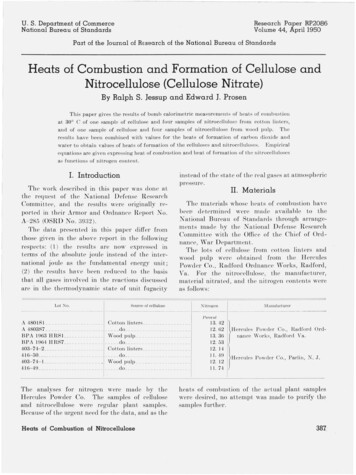
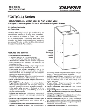
11. INSTALLATIONRequired floor, ceiling, and roof cut-out openings must be carefully located to avoid misalignment of the furnace and Roof Jack (see Figures12 & 13). Installation procedures are suggestedfor typical furnace installations and need not befollowed in the exact listed sequence.CUT OUT FLOOR OPENING & FUEL LINEHOLEa. Determine center of closet or alcove (Figure13).b. Locate center of the floor opening, measured10" from the rear wall, and mark cut-outmeasuring approximately 14-1/2" by 14-1/2"( 1”) for model duct connector used (referto Figures 10 & 11).c. Locate center of fuel line hole, measured 231/4" from the rear wall and 6-5/8" to the left ofcenter of the floor cut-out (See Figure 12) orMOUNTINGPLATE5-1/4" to the left of center of the floor cut-out,or for entry through right-side of furnacemeasured 9" to the right of center of the floorcut-out.d. Cut out floor opening and one fuel line hole.! IMPORTANT:Refer to the installation instructionsprovided with optional air conditioningpackages when installing furnaces withoptional cooling coil cabinet or withoptional C***-series indoor coils.CUT OUT CEILING AND ROOF OPENINGSa. Locate center of Roof Jack opening, measured 13 1/2" from the rear wall of closet oralcove along the center line of furnace andfloor opening. (See Figure 13)REAR WALLFLOOROPENINGFUELLINEHOLESSUPPLY AIR DUCTCUT DUCT OPENING1/16TH. LARGER THANDUCT CONNECTORFigure 14. Mounting PlateUNDER DUCT OPENINGMOUNTINGPLATEREAR ELLINEHOLESFUELLINEHOLESSUPPLY AIR DUCTNon-Platinum SeriesPlatinum Series14” SUPPLYCONNECTIONFigure 15. Duct Connector11
b. Cut ceiling and roof holes as follows:Ceiling Hole 8-3/4" (222 mm) diameterRoof Hole 9-3/8" (238 mm) diameterc. DO NOT ALLOW DEBRIS TO FALL INTOTHE FURNACE. THIS COULD CAUSEUNSAFE OPERATION AND VOIDS THEFURNACE WARRANTY. Use the top capthat comes with the furnace packaging (oralternate protector) to prevent debris fromfalling into the furnace before the final roofjack connection is made.CUT DUCT OPENING (FINGER TABBEDONLY)a. Place duct connector through the floor opening with bottom tabs resting on top of thesupply air duct.b. Center duct connector and push back againstrear edge of floor opening.c. Mark cut-out location (tab area) and removeduct connector.d. Cut out duct opening 1/4" larger than areamarked.INSTALL FURNACE MOUNTING PLATEa. Place mounting plate (supplied within ductconnector) at rear of the floor opening (SeeFigure 15).INSTALLING PLATINUM SERIES 14” ROUNDDUCT CONNECTORa. Place duct connector through the floor opening. (See Figure 15).b. Secure duct connector to floor.INSTALLING SCREW DOWN DUCT CONNECTORa. Apply a bead of caulking, mastic, or otherapproved sealant around bottom side of 1/2”flange and restrictor plate, when applicable.b. Locate the duct connector over duct andcarefully lower screw down duct connectorinto place.c. Once duct connector is located on duct,temporarily hold in place while fastening ductconnector to the floor using flat head screwsor nails. Be sure flanges of duct connectorstay in contact with the duct.d. Screw plenum to duct making sure a seal ismade between the duct and the duct connector. Additional screws may be added if required.e. Cut away duct along edge of flange allowingthe center to drop into the duct. Removesection of duct with caution, as edges will besharp.INSTALLING FINGER TABBED DUCT CONNECTORSa. Place duct connector through the floor opening with bottom tabs extending through theduct opening. (See Figure 15)b. Secure duct connector to floor.c. Bend bottom tabs under and up tightly againstthe supply air duct (See Figure 16).NOTE: The duct connector is designed for useon ducts 12" in width. When using the connectoron 12" wide ducts, there may be insufficientclearance to bend the tabs on two sides of theduct connector. In such cases the tabs may beattached to the sides of the duct by using sheetmetal screws or other suitable fasteners. (SeeFigure 17).If sealant, mastic, or tape is used to provide abetter seal, it should be approved by applicablenational or local codes.ALTERNATE ATTACHMENT METHODSThis procedure may also be used to install afurnace duct connector to narrow metalductwork where insufficient clearance preventsTABSDUCT1. INSERT DUCT CONNECTOR INTODUCT CUT-OUT.TABSDUCT2. BEND BOTTOM TABS OVERAND ONTO THE UNDERNEATHDUCT SERVICE.Figure 16. Installation of Duct ConnectorDuct ConnectorNarrow DuctDuctFigure 17.12
bending of the duct connector tabs at theside(s) of the duct. (See Figure 18).1. Score and cut the top of the metal duct asindicated in Step 1 or Step 2. With Step 1choice, also cut out the metal from the shadedarea “A”.2. Fold the duct flap “B” up, (See Step 3).3. At the front-to-back of duct run (Area “A”),bend the duct tabs and secure them directlyto the duct.4. At Area “B”, bend the duct tabs up and backover, around the duct connector, (SeeStep 3).5. Fold/form the duct flap against the side of theduct connector and attach as shown, (SeeStep 4). Use three (3) staples (minimum) oneach duct flap OR, if a 2X block/joist is notprovided, use two (2) sheet metal screws(minimum) on each duct flap. An alternateattachment method is acceptable, as long asthe duct connector is securely attached.6. Tape the duct flap edges with an approvedtape for a leak-free joint.INSTALL FURNACEa. Remove furnace outer door(s) and bottomfuel line knockout.b. Place furnace onto duct connector and center with floor opening.c. Slide onto mounting plate. (Bottom rear slotson furnace should engage with mountingplate tabs.)d. Secure front with one (1) fastener at eachcorner (See Figure 19 or 20).NOTE: Additional fasteners may be used atrear, sides or through door frame, as desired,to secure furnace to closet or alcove framing.INSTALL ROOF JACKApply caulking compound on underside of roofflashing to form a continuous strip at least 3/8"wide (see Figure 21) around the underside ofthe perimeter of the flashing. Connect RoofJack Assembly to the furnace. Insert telescoping Roof Jack Assembly through the openingcut on the roof. Connect flue pipe to flue collarof furnace. Connect combustion air pipe tofurnace collar with sheet metal screw (SeeFigure 22). It is recommended that the connection of the combustion air pipe to the furnace bemade before the flashing is secured to the roofto maintain alignment of roof jack and furnaceconnections.NOTE: For replacement furnaces, be sure theinner flue pipe connects over the furnace ventcollar. DO NOT use a smaller diameter innerflue pipe which could slide inside the furnace vent collar and restrict the flow offurnace flue products.Attach Roof Flashing: If necessary, shift roofflashing slightly in the roof opening so thatassembly is in good alignment with furnace.Press down firmly over caulking on roof flashingto make the seal with roof water tight. Secureflashing with appropriate fasteners. As anSTEP 2.STEP 1.Fold Back Flap "B"Cut- OutArea "A"Fold Back Flap"B""B""A""A""A""A""B"Cut- OutArea"A"CutLinesDuct"B"Top of DuctFold Back Flap"B"Fold Back Flap "B"Staple Folded DuctFlap (typ) to side of DuctConnectorBend Duct Connector Tabs Upand Over- (along length of duct)Duct"B"DuctFlap "B"DuctSTEP 4.STEP 3.Figure 18.13
added protection against leaks, coat the flashing plate and fasteners with approved roofingcompound.SLIDE FURNACEALL THE WAY BACKONTO MTG. PLATEMTG. PLATE TABSSECURE FURNACEWITH 2 FASTENERS AT FRONTCORNER HOLES12. INSTALLATION OF TRANSITMODE VENTING SYSTEMKnockout Over HolesSUPPLY AIR DUCTFigure 19. “A”, “B”, & PlatinumCabinet FurnacesSLIDE FURNACEALL THE WAY BACKONTO MTG. PLATEMTG. PLATE TABSSECURE FURNACEWITH 2 FASTENERSAT FRONT CORNER HOLESFUELLINEHOLESSUPPLY AIR DUCTFigure 20. “A” Cabinet Furnace on 911969Coil Cabinet (Non-Platinum Series)Secure Roof Jack withappropriate fastenersafter connecting ;;;;;;;;;;;;;;;;
M1 Series gas and oil furnaces are listed direct vent (sealed combustion), downflow heating appliances for manufactured (mobile) homes, recreational vehicles, and for use in residential/ modular/commercial construction. The furnace must be located so that venting can be properly achieved.