Transcription
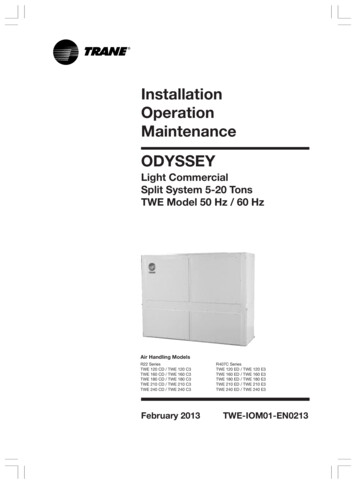
InstallationOperationMaintenanceODYSSEYLight CommercialSplit System 5-20 TonsTWE Model 50 Hz / 60 HzAir Handling ModelsR22 SeriesTWE 120 CD / TWE 120 C3TWE 160 CD / TWE 160 C3TWE 180 CD / TWE 180 C3TWE 210 CD / TWE 210 C3TWE 240 CD / TWE 240 C3February 2013R407C SeriesTWE 120 ED / TWE 120 E3TWE 160 ED / TWE 160 E3TWE 180 ED / TWE 180 E3TWE 210 ED / TWE 210 E3TWE 240 ED / TWE 240 E3TWE-IOM01-EN0213
Model NomenclatureAir Handling UnitModel NomenclatureTWE 120 C D 0 0 A ATWE Cooling Only and Heat PumpAir Handling Unit (Convertible)Nominal Gross Cooling Capacity (MBH)120 120 MBH160 160 MBH180 180 MBHFor TWE model210 210 MBH240 240 MBHMajor Design SequenceC R22 RefrigerantE R407C RefrigerantService DigitA First Parts ListMinor Design SequenceA First Design SequenceB Second Design SequenceC Third Design SequenceFactory Installed Options # 20 No OptionsA Discharge Plenum(Vertical application)B Return Air GrilleC Discharge Plenum and Return Air GrilleS Special request to be defined and approvedFactory Installed Options # 10 No OptionsA 1 HP Fan MotorB 2 HP Fan MotorC 3 HP Fan MotorD 5 HP Fan MotorE 7.5 HP Fan MotorElectrical CharacteristicsD 380-415/3/503 230/3/602TWE-IOM01-EN0213
ContentsTWE-IOM01-EN0213Model Nomenclature2General Information4Unit Installation5General Data10Electrical Wiring11Dimensional Data12Operation and Start-up17Maintenance18Trouble Shooting193
General InformationForewordThese instructions do not attempt tocover all variations in systems, nor toprovide for every possible contingencyto be met in connection withinstallation. Should further informationbe desired or should particularproblems arise which are notsufficiently covered for the purchaser’spurpose, the matter should be referredto the manufacturer.ReceptionOn arrival, inspect the unit beforesigning the delivery note. Specify anydamage on the delivery note, and senda registered letter of protest to the lastcarrier of the goods within 72 hoursof delivery. Notify the local Trane SalesOffice at the same time. The unitshould be totally inspected within 15days of delivery. If any concealeddamage is discovered, stop unpackingthe shipment. Take photos of thedamage material if possible. Notify thecarrier immediately by phone andregistered mail. Notify the local TraneSales Office. Concealed damage mustbe reported within 15 days of delivery.Check the unit nameplate to confirmthat the proper unit was shipped.Available power supply must becompatible with electricalcharacteristics specified oncomponent nameplates.General InformationThis manual covers the InstallationOperation, and Maintenance of theTWE120C single circuit air handlers,and the TWE160C, TWE180C,TWE210C and TWE240C dual circuitair handlers. These new air handlermodels are completely redesigned toincorporate a single slab coilassembly, improved applicationflexibility, servicing and maintenanceaccessibility, and an improvedaccessory line. They are of the fullyconvertible type (vertical to horizontal)without field removal or re-orientationof the coil assembly. (For TWE model)They are shipped in the verticalposition.4All unit (both single and dual circuits),have one drain pan that can beinstalled in any one of four positions.This allows for vertical or horizontalapplications and left or right exit.Note: “Warnings” and “Cautions”appear at appropriate places inthis manual. Your personalsafety and the proper operationof this machine require that youfollow them carefully. Themanufacturer assumes noliability for installations orservicing performed byunqualified personnel.HandlingThe unit will be supplied with ashipping base and protectivepackaging over the unit casing. Thepackaging should be kept on the unitduring handling or storage on site.If it is necessary to remove thepackaging for inspection prior tocompletion of on site handling, retainpackaging parts and reapply them bytapping in position to prevent damageto the casing. The unit as supplied hasa shipping base which is suitable forhandling by a fork lift truck. If it isnecessary to sling the unit, usespreader bars under the shippingbase. Ensure that ropes do not causeabrasion to the surface of the unit.WARNING:Open andlock unit disconnect to preventinjury or death from electricshock or contact with movingparts before attempting anyinstallation or maintenance.InspectionInspect material carefully for anyshipping damage. If damaged, it mustbe reported to, and claims madeagainst the transportation company.Replace damaged parts withauthorized parts only. Check the unitnameplate to confirm that the properunit was shipped. Available withelectrical characteristics specified oncomponent nameplates.TWE-IOM01-EN0213
Unit InstallationTable 1 - Total unit weight and corner weights 7069727190899190Installations, Limitations andRecommendationsThe general location of the air handleris normally selected by the architect,contractor and/or buyer. For properinstallation, the following items mustbe considered.a. Available power supply must agreewith electrical data on componentnameplate.b. Air handler shipped wired for 380volt applications.c. If external accessories are installedon the unit, additional clearancemust be provided.d. All duct work should be properlyinsulated to prevent condensationand heat loss.e. Refrigerant gas piping must beinsulated.Caution: Properly insulate allrefrigerant gas piping to preventpossible water damage due tocondensation and to preventcapacity loss and possiblecompressor damage.It is recommended that the outlinedrawings (Pages 12-14) be studiedand dimensions properly noted andchecked against selected installationsite. By noting in advance whichknockouts are to be used, properclearance allowances can be made forinstallation and possible future service.Important: If adding externalaccessories to the unit,additional clearances must beconsidered for the overall spaceneeded.TWE-IOM01-EN0213Corner WeightsWhen installing these units “freestanding” with discharge grills andisolaters, a top support with isolatershould be added to prevent tipping.Support and isolater can be attachedto a wall or other appropriate structure.Caution : Use spreader bars toprevent straps from damagingthe unit. Install the bars betweenlifting straps, both underneaththe unit and above the unit. Thiswill prevent the straps fromcrushing the unit cabinet ordamaging the unit finish.Installation ConsiderationFor proper installation and operation,check each of the following beforemounting the units.a. Space Requirement andClearanceAllow adequate space for the unit andfree air or service clearance. SeeFigure 1a.For installation of accessoriesavailable for this air handler, followthe instructions packed with eachaccessory.900 mm.Lifting RecommendationsBefore preparing the unit for lifting, thecenter of gravity should be determinedfor lifting safety. Because ofplacement of internal components, theunit weight may be unevenlydistributed. Approximate total unitweight and corner weights are given inTable 1.WARNING: On sitelifting equipment must becapable of lifting the weight ofthe unit with an adequate safetyfactor. The use of under-capacitylifting devices may result inpersonal injury or death andcause damage to the unit.The crated unit can be moved using aforklift of suitable capacity. For liftingthe unit into an elevated mountingposition, run lifting straps or slingsunder the unit and attach securely tothe lifting device. Use spreader barsto protect the unit casing from damage. Test lift the unit to determineproper balance and stability.850 mm.850 mm.Figure 1aSpace requirement for TWE modelVertical TypeFor servicing and routine maintenance,provide access to the unit throughremovable panels in the ceiling seeFigure 1b.850 mm.850 mm.850 mm.Figure 1bSpace requirement for TWE modelHorizontal Type5
Unit Installationb. Location, Mounting andPositioningBefore installing any unit make sureproper preparation has been made ateach unit locating for piping andelectrical connections.W#4Caution: Before hanging the uniton suspension rods, reinforcethe cabinet around theknockouts, using a large washerinside the cabinet. Washershould be between the skin ofthe air handler and the nut onthe suspension rod.W#3Align holes (knockouts) in the cabinetwith structural supports and securesuspensions rods to the structure, thento the air handler cabinet. If knockoutlocations do not permit proper alignmentwith existing structure, it may benecessary to field fabricate crossmembers on existing structural beams.W#2W#1Note: When other than bottomreturn is to be used, side panelremoved for return ductinstallation, must be securedover the bottom opening.LevelingFigure 2aW#3W#2W#4W#1Figure 2bHorizontal SuspensionIf the air handler will be suspended, usea suspension mounting kit to isolate theunit from the structure. This is usuallyaccomplished through the use of springor rubber isolators, which are offered asan accessory. Mounting rods must befield supplied. Isolator selection isdependent upon total unit weight,including accessories. Approximate unitweights are provided in Table 1.6This air handler has a double slopeddrain pan. In order to assure properdrainage along the length of drain pan, itis important to have the unit properlyleveled. Be sure the air handler is levelor slightly sloped in the direction of thecondensate connection.Refrigerant Piping PreparationThe air handler is designed so thatrefrigerant piping can enter from eitherthe left or right hand side. The airhandler is shipped with the intent, thatthe refrigerant, lines will enter from theright hand side. To convert to left handentry, unbraze the elbow on the suctionline and rotate 180 degrees and rebraze.(See Figures 3 and 4).Caution: Protect adjacentsurfaces from heat damage,when brazing in and around theair handler.These air handlers are shippedwith a holding charge in the coil.Cut the process tube or puncturethe cap to bleed off the nitrogenprior to any brazing. Temporarilycap off tubes if the refrigerantline connections are to be madelater. You will find a cloth bagthat contains two (2) brassclamps (straps) and cork"impregnated insulation materialapproximately 9" long by 4"wide, for attaching and insulating the expansion valve bulb tothe suction line. On dual circuitsair handlers there will be two (2)cloth bags with like parts.Auxiliary Drain PanRefrigerant PipingA field fabricated auxiliary drain panshould be installed under the unit for allhorizontal applications, and when airhandlers are installed above ceilings orin other locations where condensateoverflow may cause damage. This drainpan will eliminate any excesscondensation that may be due toextreme humidity or an obstructed drainin the primary drain pan. Drain linesfrom this pan must be installed, butshould not be connected to the primarydrain line from the unit, isolate theauxiliary drain pan from both the airhandler and the structure.Installation, brazing, leak testing, andevacuation of refrigerant lines arecovered in the installation instructionspackaged with the outdoor unit. Readthe instructions before beginninginstallation of refrigerant lines.On air handlers that will have refrigerantlines entering the cabinet from the rightside, remove the split rubber grommetfrom the knockout in the end of the airhandler. Uncoil the cap tube with thebulb attached at the expansion valveand place the grommet on the cap tube.With the grommet around the tube, pushthe bulb through the hold and positionthe grommet back into it’s originalposition. One bulb and cap tube onsingle circuit units and 2 bulb (s)approximately 45 degrees off vertical, 10to 12 inches outside of the air handler.(See Figure 3 and 4.)Installation PreparationsThe final position must be dictated byrequired service access to unit, weightdistribution over structural supports, andby the locations of electrical, refrigerantand condensate drainage connections.TWE-IOM01-EN0213
Unit InstallationOn air handlers that will haverefrigerant lines entering the cabinetfrom the left side, the bulb(s) should beattached to the suction tube(s) insidethe cabinet, in the same manner asabove, approximately 10" from the leftend of the unit.After attaching to the suction line(s),either inside or outside of the cabinet,wrap the cork impregnated insulationaround the bulb(s) and suction tube(s).Refrigerant piping should then rtant : Ensure that therefrigerant lines passing throughthe cabinet are not resting onsharp sheet metal edges.DRAIN PANVERTICALDRAIN CONNECTIONSFigure 53/4" GALVANIZEDPIPE & FITTINGSNIPPLERepositioning Drain PanMaterials1Tea4" MIN.NIPPLE2"DIA3/4"DIALEFT SIDE HOOK UP(OPTIONAL)RIGHT SIDE HOOKUP (STANDARD)2-3/4"MIN.1Plug3Street Ell15-1/2" NippleFigure 6aThese air handlers come with onedrain pan that can be installed in anyone of four positions; this allows forvertical or horizontal application andleft or right condensate lineconnection. The drain pan can also beeasily removed for periodic cleaning.Figure 33/4" PVC OR COPPERTUBING & FITTINGSNIPPLE4" MIN.2-3/4"MIN.NIPPLE2"DIA3/4"DIALEFT SIDE HOOK UP(OPTIONAL)RIGHT SIDE HOOKUP (STANDARD)Materials1Tea390" Ell1Plug16" Nipple22" Nipple13/4" NPT to PVCor copper adapterFigure 6bFigure 4Condensate PipingThe drain pan condensate connectionis a female slip joint type for 1" ABSpipe. Use PVC cement and tubing asrequired (field supplied) to construct atrap. A union or flexible tubing andclamp may be installed if the drain panis to be removed periodically forcleaning. If the air handlers have metaldrain pans, the nipples will have plugsfactory installed. When it has beendecided which nipple is to be used,remove the plug from that nipple only.TWE-IOM01-EN0213Important: When air handler isinstalled in the vertical positionand close proximity trapping ofcondensate is required, use of asubbase accessory to raise theair handler for clearance of thedrain trap is recommended. Fora typical drain trap assembly, seefigure 6a and 6b.Important: All air handlers areshipped with the drain paninstalled in the horizontalposition and the connection onthe right side (as shown in figure5). If an alternate position isrequired, the drain pan should berepositioned before setting theair handler.Step1. Remove the access plate at theopposite end of the drain connection.This plate secures and lifts the backend of the drain pan for sloping. Itmust be removed before the drain pancan be removed. This is done asfollows: (A) remove the screw, (B) liftthe access plate up, (C) pull the plateout. If the drain pan is to be moved tothe vertical position also remove theother two access plates.7
Step 2. (A) Remove the screw securingthe drain pan. (B) Lift the pan up. (C)Slide the pan out.FiltersCStep 3. Install the drain pan into thenew position. (A) Slide the drain paninto the opening. (B) Lift the drain panup. (C) Push it in all the way. (D) Drop itdown over the lip of the opening.Secure with screw.Step 4. Install the access plate on theopposite end of the drain pain. (A)Slide the edge of the access plateunder the drain pan. (B) Lift the accessplate and drain pan up. (C) Push theaccess plate in. (D) Drop the accessplate down over the lip of the opening.Secure with screw. If the drain pan isbeing move to the vertical position,install the other access plates over thehorizontal position opening.BAAir handlers are shipped with 1"washable filters installed. To replacefilters, remove lower access panel(either end) and slide old filters out andreplace with new ones See Figure 7.STEP 1BREMOVE 4 SCREWS ANDANGLE TO USE 2" FILTERCAFigure 7STEP 2DSTEP 3ABCCD BSTEP 4ACCESS PLATEALTERNATIVE DRAIN PAN LOCATIONFOR VERTICAL APPLICATIONADRAIN PAN LOCATIONHORIZONTAL APPLICATION8TWE-IOM01-EN0213
Unit InstallationFLANGKTo convert from a 1" filter to a 2" filteron units so equipped, remove loweraccess panels from both ends of theair handler. Remove two (2) screwsand the L shaped angles from both thetop and bottom of the filter track toincrease the width of the filter opening(see figure 7). The screws and Lshaped angles can be discarded orsaved for possible future use.KNOCKOUTUNIT POWER ENTRYDuct ConnectionsThe supply and return ducts should beconnected to the unit with flameretardant duct connectors to reducevibration transmission. The return ductshould be sized to the samedimensions as the return inlet of theunit.WARNING: Wheninstalling or servicing thisequipment, always exercisebasic safety precautions to avoidthe possibility of electric shockthat could result in severepersonal injury or death.Figure 8Thermostat & ControlConnection1. Observe all notes on thesediagrams.2. Mount the thermostat in the desiredlocation.3. Install color coded cables betweenoutdoor unit, indoor unit andthermostat.4. Connect control wiring to theterminal board located on the sideof the fan control box.Electrical Connections1. All electrical lines, sizing, protection,and grounding must be inaccordance with local codes.2. If conduit is used, isolate whenevervibration transmission may cause anoise problem within the buildingstructure.3. Ensure all connections are tight andno wires exposed.4. All accessories must be installedand wired according to theinstructions packaged with thataccessory.For air handler power entry only, or fordual power entry (power entry for airhandler) the electrical connections aremade in the fan control box located inthe right side of the air handler. Wiringentrance is through holes provided inthe end of the air handler cabinet (seeFigure 8). Breaker or fuse size can beselected using the nameplatesattached to unit.Single point power entry is used, (onepower entry for air handler).TWE-IOM01-EN0213Table 2 - RecommendedThermostat Wire SizeWire SizeMaximum Wire Length(Physical Distancebetween Unit and T-stat)22 - gauge20 - gauge18 - gauge16 - gauge14 - gauge30 feet50 feet75 feet125 feet200 feetInstallation ChecklistComplete this checklist once the unitis installed to verify that allrecommended procedures have beenaccomplished before the system isstarted.Operational checks cannot beperformed until the systeminterconnection is complete. Verify that the unit electrical poweris disconnected. Inspect all field wiring connections.All connections should be clean andtight. Inspect unit ground connection(s).Ground must comply with allapplicable codes. Inspect unit suspensionarrangement (if used). Unit positionmust be secure. Remove any toolsor debris found in or near the unit. Inspect duct outlets. Outlets mustbe open and unrestricted. Inspect unit drain lines. Pipeconnections must be tight and drainline unrestricted. Inspect fan assembly to insure allmoving parts move freely. If unit is horizontally mounted, makesure secondary drain pan has beeninstalled. Inspect unit for proper filters,securely installed. All cabinetpanels must be secured. Inspect owner/operator on propersystem operating andmaintenanced procedure.Checkout ProcedureComplete the “Installation Checklist”at the end of this manual onceinstalled all field wiring connections.All operational checks (unit running)must be made after outdoor unit isinstalled and system interconnection iscomplete.9
General DataUNIT MODELSPOWER CONNECTIONMCA1SYSTEM DATARefrigerant TypeNo. Refrigerant CircuitsRefrigerant Connection TypeSuction Line ODLiquid line ODCASINGMaterialColorType of InsulationCOILFace AreaTube Size ODTube TypeRowsFins per inchRefrigerant Flow ControlDrain Connection SizeDrain Connection TypeFANFan TypeNo. usedDiameterWidthDrive TypeNominal Airflow 2MOTORMotor TypeNo. of MotorMotor hpNo. of SpeedMotor SpeedV/ph/HzRLA/LRAFILTERTypeNo. usedSize (WxLxD)DIMENSION (HxWxD)Crated (Shipping)Uncrated (Net)WEIGHTUncrated (Net)1MCA - Minimum Circuit Ampacity2CFM is rated with standard air-dry coil.UNIT MODELSPOWER CONNECTIONMCA1SYSTEM DATARefrigerant TypeNo. Refrigerant CircuitsRefrigerant Connection TypeSuction Line ODLiquid line ODCASINGMaterialColorType of InsulationCOILFace AreaTube Size ODTube TypeRowsFins per inchRefrigerant Flow ControlDrain Connection SizeDrain Connection TypeFANFan TypeNo. usedDiameterWidthDrive TypeNominal Airflow 2MOTORMotor TypeNo. of MotorMotor hpNo. of SpeedMotor SpeedV/ph/HzRLA/LRAFILTERTypeNo. usedSize (WxLxD)DIMENSION (HxWxD)Crated (Shipping)Uncrated (Net)WEIGHTUncrated (Net)1MCA - Minimum Circuit Ampacity2CFM is rated with standard air-dry D/ED380-415/3/5010.0TWE240CD/ED380-415/3/5010.0in (mm)in (mm)R22/R407C1BRAZE1 3/8 (34.93)1/2 (12.7)R22/R407C2BRAZE1 1/8 (28.58)1/2 (12.7)R22/R407C2BRAZE1 3/8 (34.93)1/2 (12.7)R22/R407C2BRAZE1 3/8 (34.93)1/2 (12.7)R22/R407C2BRAZE1 3/8 (34.93)1/2 (12.7)16.3 (1.51)3/8 (9.53)18(1.67)3/8 (9.53)Galvanized & Electro-galvanized SteelLight Gray10mm Fire Retardant Polyethylene Foamsq ft (m 2)in (mm)9.6(0.89)3/8 (9.53)12.7 (1.18)3/8 (9.53)314314in (mm)1 (25.4)1 (25.4)in (mm)in (mm)115 (381.0)15 (381.0)118 (457.2)18 (457.2)cfmhp (kW)rpm4000530012 (1.5)11405380-415/3/503.66 - 21.012 (1.5)11405380-415/3/503.66 - 21.014 (1.47)3/8 (9.53)INNER GROOVED TUBE312EXPANSION VALVE1 (25.4)PLASTIC - FEMALE PIPEDOUBLE INLET CENTRIFUGAL WITH FORWARD CURVED WHEEL118 (457.2)18 (457.2)BELT-ADJUSTABLE DRIVE60003153151 (25.4)1 (25.4)215 (381.0)15 (381.0)215 (381.0)15 (381.0)7000TOTALLY ENCLOSED-FAN COOLED, THREE PHASE INDUCTION MOTOR113 (2.2)3 (2.2)1114251425380-415/3/50380-415/3/505.08 - 34.05.08 - 34.0800015 (3.7)11440380-415/3/508.03 - 63mm4355 x 635 x 254927x400x25WASHABLE ALUMINUM AIR FILTER4927x400x254555 x 727 x 254555 x 727 x 25mmmm1651 x 1499 x 7241523 x 1410 x 6351867 x 1702 x 9391751 x 1613 x 8501867 x 1702 x 9391751 x 1613 x 8501867 x 2299 x 7941751 x 2210 x 7021867 x 2299 x 7941751 x 2210 x 0C3/E3230/3/6010.0in (mm)in (mm)R221BRAZE1 3/8 (34.93)1/2 (12.7)R222BRAZE1 1/8 (28.58)1/2 (12.7)R222BRAZE1 3/8 (34.93)1/2 (12.7)R222BRAZE1 3/8 (34.93)1/2 (12.7)R222BRAZE1 3/8 (34.93)1/2 (12.7)sq ft (m 2)in (mm)9.6(0.89)3/8 (9.53)12.7 (1.18)3/8 (9.53)16.3 (1.51)3/8 (9.53)18(1.67)3/8 (9.53)314314in (mm)1 (25.4)1 (25.4)in (mm)in (mm)115 (381.0)15 (381.0)118 (457.2)18 (457.2)TWE240C3/E3230/3/6016.6Galvanized & Electro-galvanized SteelLight Gray10mm Fire Retardant Polyethylene Foamcfmhp (kW)rpm4000530012 (1.5)11705230/3/605.85-3912 (1.5)11705230/3/605.85-3914 (1.47)3/8 (9.53)INNER GROOVED TUBE312EXPANSION VALVE1 (25.4)PLASTIC - FEMALE PIPEDOUBLE INLET CENTRIFUGAL WITH FORWARD CURVED WHEEL118 (457.2)18 (457.2)BELT-ADJUSTABLE DRIVE60003153151 (25.4)1 (25.4)215 (381.0)15 (381.0)215 (381.0)15 (381.0)7000TOTALLY ENCLOSED-FAN COOLED, THREE PHASE INDUCTION MOTOR113 (2.2)3 5 (3.7)11730230/3/6013.3-95mm4355 x 635 x 254927x400x25WASHABLE ALUMINUM AIR FILTER4927x400x254555 x 727 x 254555 x 727 x 25mmmm1651 x 1499 x 7241523 x 1410 x 6351867 x 1702 x 9391751 x 1613 x 8501867 x 1702 x 9391751 x 1613 x 8501867 x 2299 x 7941751 x 2210 x 7021867 x 2299 x 7941751 x 2210 x 702kg152.5273.5283353360TWE-IOM01-EN0213
Electrical WiringTWE120-240 (EXPORT)POWER CONTROL BOXTBPT3M–1L1I.D.MOTOR3M–2L23M–3EXTERNAL CONTROLPOWER SUPPLY220–230V./1PH./50Hz./60Hz.L3{O.L.C1TTA 075,100,120RD1396C2C3TO TERMINAL BLOCKTTA MODELS952M/3MTTA 150,180,200,240RD23TH2M1/3M1/A113TO PUSH BUTTON “2PB”{2M1,2M2 TTA 075,100,120RD003M1,3M2 TTA 150,180,200,240RD00A1,A2 TTA ONDESCRIPTION1MTB2M1,2M2,3M13M2,A1,A2CONTACTOR BLOWER MOTOR.TERMINAL BLOCKAUXILIARY N.O. CONTACTAUXILIARY N.O. CONTACTTH2PBTHERMOSTATSWITCH PUSH BUTTONFACTORY WIRING & DEVICE BY MFR.ID. MOTORPTNOTES1. ALL FIELD WIRING TO BE IN ACCORDANCE WITH NATIONAL ELECTRICCODE (N.E.C.) CANADIAN ELECTRIC CODE AND/OR LOCAL STATE ANDCITY CODES. PROVIDE DISCONNECTS FOR ALL POWER SUPPLIES.2. DRAWING PRACTICES AND SYMBOLS ARE IN ACCORDANCE WITH AIRCONDITIONING & REFRIGERATION INSTITUTE (ARI) GRAPHICELECTRICAL STANDARDS.3. COMPONENT TERMINAL MARKINGS ARE INDICATED BY ENCIRCLEDNUMBERS AND/OR LETTERS.4. NUMBERS ON VERTICAL & HORIZONTAL LINE ARE CIRCUIT IDENTIFICATION.5. THIS UNIT TO BE USED WITH EVAPORATORS OPERATING WITH INA TEMPERATURE RANGE OF 32ºF TO 53.5ºF.FIELD WIRINGINDUCTION MOTORPOWER TERMINALFUSETWE120-240 (DOMESTIC)POWER CEDESIGNATIONTBDESCRIPTIONTERMINAL BLOCKFACTORY WIRING & DEVICE BY MFR.FIELD WIRINGID. MOTORINDUCTION MOTOR 380V. 3PH. 50HZ.Caution : Disconnect the power supply before opening the control box or servicing.TWE-IOM01-EN021311
Dimensional DataTWE 120 CD / C3TWE 120 ED / 2131275A3H10I4NMJKL84095RETURN AIR OPENINGWATER LADDER* FOR HORIZONTAL APPLICATION ONLY1268VERTICAL4473HORIZONTAL140911 PULLEY FAN6 BLOWERLOW VOLTAGE ENTRANCE ø7/8"2HIGH VOLTAGE ENTRANCE ø7/8"7MOTOR12 PULLEY MOTOR3LIQUID HOLE ø7/8"8EVAPORATOR COIL13 BELT4SUCTION HOLE ø2"9ACCESS PANEL5DRAIN CONNECTION ø1"RETURN AIR OPENING73126848HORIZONTALModel No.TWE120Model No.TWE1201210 FILTER ACCESS PANELDimensions 40530578282Dimensions mm.TWE-IOM01-EN0213
Dimensional DataTWE 160-180 CD / C3TWE 160-180 ED / 2131275A3I10H4POKLMJN85885WATER LADDERRETURN AIR OPENING* FOR HORIZONTAL APPLICATION ONLYHORIZONTAL14678673VERTICAL588RETURN AIR OPENING146790731 LOW VOLTAGE ENTRANCE ø7/8"6 BLOWER11 PULLEY FAN2 HIGH VOLTAGE ENTRANCE ø7/8"7 MOTOR12 PULLEY MOTOR3 LIQUID HOLES ø7/8"8 EVAPORATOR COIL13 BELT4 SUCTION HOLES ø2"9 ACCESS PANEL5 DRAIN CONNECTION ø1"10 FILTER ACCESS PANELHORIZONTALModel No.TWE160/180Model No.TWE160/180TWE-IOM01-EN0213Dimensions 933922982403077429Dimensions mm.13
Dimensional DataTWE 210-240 CD / C3TWE 210-240 ED / 52148136A3H411IRQOMNLJKP59446RETURN AIR OPENING46RETURN AIR OPENINGWATER LADDER7398698693* FOR HORIZONTAL APPLICATION ONLYVERTICAL446RETURN AIR OPENINGHORIZONTAL73986986901LOW VOLTAGE ENTRANCE ø7/8"6DRAIN CONNECTION ø1"11 FILTER ACCESS PANEL2HIGH VOLTAGE ENTRANCE ø7/8"7BLOWER12 PULLEY FAN3LIQUID HOLES ø7/8"8MOTOR13 PULLEY MOTOR4HOLE FOR TXV BULB ø7/8"9EVAPORATOR COIL14 BELT5SUCTION HOLES ø2"10 ACCESS PANELRETURN AIR OPENINGHORIZONTALDimensions mm.Model 248Dimensions mm.Model WE-IOM01-EN0213
Dimensional DataTWE 120TWE 160-180With Plenum (Option)SUPPLY AIR GRILLE(DOUBLE DEFLECTION)CFGDEBAHERETURN AIR GRILLEDFVERTICALHORIZONTAL*(Special option)BGSUPPLY AIR GRILLE(DOUBLE DEFLECTION)ADimensions (mm.)Model 52Note: Horizontal applications with discharge plenum is special option, please contact Trane sales office.TWE-IOM01-EN021315
Dimensional DataTWE 210-240With Plenum (Option)GDHEFSUPPLY AIR GRILLE(DOUBLE DEFLECTION)BCBAFIEGRETURN AIR GRILLEVERTICALHORIZONTAL*B(Special option)CHBSUPPLY AIR GRILLE(DOUBLE DEFLECTION)ADimensions (mm.)Model 62100679484986047042216103Note: Horizontal applications with discharge plenum is special option, please contact Trane sales office.16TWE-IOM01-EN0213
Operation and Start-upPreparationStart-Up ProceduresPerform the following checks andinspections before operating the unit:After completing all times under“Pre-Start-Up”, the unit may be startedand the following checks and adjustments performed.Inspection Checklist Unit is mounted securely to theceiling support rods (mountingunits). Ductwork connections arecomplete. Coil connections are complete andtight. Condensate drain pan connectionsare complete and tight. Electrical connections arecompleted. Wiring is correct and inaccordance with the wiring diagram. Ground connection is completed. Check and retighten if necessaryset screws on the drive, fan pulley,fan bearings and wheel. Rotate fan by hand, to ensure that itruns freely and that there is nointerference. Check that fan is centrally located inthe housing, axially and radially. Check and retighten, if necessary,drive and bearing bolts, motorclamp plate bolts and isolator bolts. Check to ensure that pulley arecorrectly aligned and that shafts areparallel. Check belt tension as perinstruction given in the maintenancesection.TWE-IOM01-EN02013a. Measure the motor voltage andamps on all phases to insure properoperation. Compare these readingswith the motor nameplate.b. Disconnect load and start motor tocheck the direction of rotation. Ifthe rotation need to be changed,stop the motor completely andchange the direction of rotation.c. After connecting the load, the motorshould start quickly and runsmoothly. If it does not, the powersupply should be switched off atonce and all connections, as well asthe power supply, be re-checkedbefore re-starting.d. In the event of excessive vibrationsor unusual noises, the motor shouldbe disconnected from the load andchecked for poor alignment, loosemounting bolts, etc.e. When the motor has been operatedunder load for a short period oftime, check that the operatingcurrent totally with the nameplatecurrent.17
MaintenanceWarningDisconnect electrical power sourceand secure in disconnected positionbefore servicing the unit. Failure to doso may result in personal injury ordeath from electrical shock.Monthly Inspection1. Check condition of air filters andreplace them if necessary.2. Che
R407C Series. 2 TWE-IOM01-EN0213 Model Nomenclature Air Handling Unit Model Nomenclature T W E 1 2 0 C D 0 0 A A TWE Cooling Only and Heat Pump Air Handling Unit (Convertible) Nominal Gross Cooling Capacity (MBH) 120 120 MBH 160 160 MBH 180 180 MBH For TWE model 210 210 MBH .