Transcription
Publication VITero Kiuru, Krista Dahlberg, Juha Mallat, Antti V. Räisänen, and Tapani Närhi.2011. Comparison of low-frequency and microwave frequency capacitancedetermination techniques for mm-wave Schottky diodes. In: Proceedings of the6th European Microwave Integrated Circuits Conference (EuMIC 2011).Manchester, UK. 10-11 October 2011. Pages 53-56. ISBN 978-2-87487-023-1. 2011 European Microwave Association (EuMA)Reprinted, with permission, from IEEE.This material is posted here with permission of the IEEE. Such permission ofthe IEEE does not in any way imply IEEE endorsement of any ofAalto University's products or services. Internal or personal use of thismaterial is permitted. However, permission to reprint/republish thismaterial for advertising or promotional purposes or for creating new collectiveworks for resale or redistribution must be obtained from the IEEE by writing topubs-permissions@ieee.org.By choosing to view this document, you agree to all provisions of the copyrightlaws protecting it.
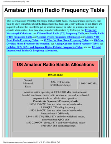
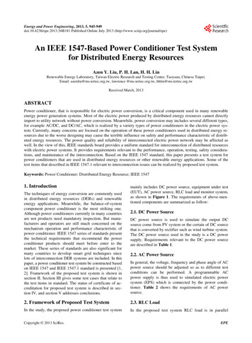
Proceedings of the 6th European Microwave Integrated Circuits ConferenceComparison of Low-Frequency and MicrowaveFrequency Capacitance Determination Techniquesfor Mm-Wave Schottky DiodesTero Kiuru, Krista Dahlberg, Juha Mallat, and Antti V. RäisänenTapani NärhiMilliLab, SMARAD, Department of Radio Science and EngineeringAalto University School of Electrical Engineering, Espoo, Finlandtero.kiuru@aalto.fiRF Payload Systems DivisionEuropean Space AgencyNoordwijk, The Netherlands(C-V) parameters are then solved by fitting the results to anonlinear capacitance equation in a least-squares sense.Abstract—The differences of low-frequency (1.0 MHz) and highfrequency (3 - 10 GHz) capacitance determination techniques arecompared in this work. The low-frequency measurements aredirect capacitance measurements performed with an LCR meterand the capacitance determination at microwave frequencies isdone by extracting the capacitance from S-parametermeasurement results. Several discrete and monolithicallyintegrated Schottky diodes are measured with both techniquesand the differences of the techniques are discussed in the view ofthe obtained results. An evaluation is made on which technique isbetter suited for building a valid capacitance model for aSchottky diode operating at millimeter wave frequencies.In this work the low-frequency measurement techniqueusing an LCR Meter and the capacitance determination fromon-wafer S-parameter measurements are compared and thedifferences of the techniques are discussed based on themeasurement results. It is also shown that in the presence oftrap states of with monolithically integraged diode thetraditional low-frequency determination does not providereliable results. C-V parameters of several mixer diodes,discrete and monolithically integrated, are determined usingboth techniques. The monolithic diodes are fabricated usingUnited Monolithic Semiconductors (UMS) BES process. Thediscrete Schottky diodes are 1MSQ08 from AdvancedCompound Semiconductor Technologies (ACST), Darmstadt,Germany and SC2T6 from Virginia Diodes Inc. (VDI),Virginia, USA. To the authors’ knowledge this is the firstreport of a quantitative comparison of low-frequency andmicrowave frequency capacitance determination techniques formillimeter wave Schottky diodes.Keywords-component; Schottky diode, capacitance-voltage,parameter extractionI.INTRODUCTIONThe capacitance of a Schottky diode is a parameter ofimportance for the high frequency performance of the diode asthe core element of a mixer, detector, or a frequency multiplier.The Schottky diode capacitance can be divided into thejunction capacitance and parasitic capacitance. The junctioncapacitance and the series resistance create an RC circuit,which limits the highest operating frequency of the diode. Alarge nonlinear junction capacitance also makes the matchingmore difficult as the diode impedance becomes dependent onthe power of the input or LO signals [1]. A large parasiticcapacitance in turn impedes a wideband matching of the deviceas a large complex conjugate embedding impedance is difficultto realize over a wide bandwidth.The capacitance of a diode can be determined by a numberof ways. One can use theoretical calculations [2], physicalsimulations [3], 3D electromagnetic modelling [4], [5], lowfrequency measurements with an impedance analyzer [6] orwith an LCR meter [7], [8] or extraction from microwavemeasurements [9], [10]. A low-frequency measurement orextraction from microwave measurements yields a value for thetotal capacitance of the diode. The junction capacitance andparasitic capacitance along with other capacitance-voltage978-2-87487-023-1 2011 EuMAFigure 1. Photographs of a) the test mount for discrete diodes and b) diodeattached on the test mount.II.MEASUREMENTS TECHNIQUES AND C-V PARAMETEREXTRACTIONFor the tests, the discrete diodes are attached on coplanarwaveguide (CPW) test mounts fabricated on 254 µm thick5310-11 October 2011, Manchester, UK
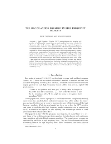
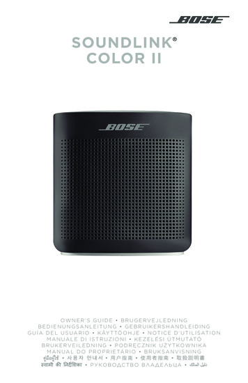
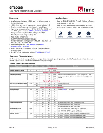
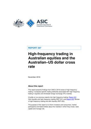
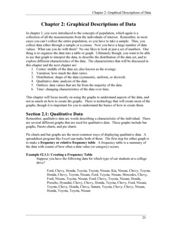
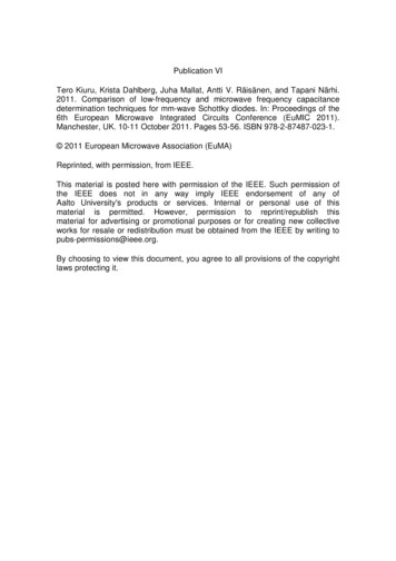
estimate for the total capacitance can be extracted. The Sparameters are measured with an Agilent N5250 PNA. The RFpower level is kept under -25 dBm at all times. The contact tothe CPW pads is done with on-wafer probes. Before themeasurements, the system is calibrated using a CascadeMicrotech line-reflect-reflect-match (LRRM) calibration kit.fused quartz substrate with 3 µm gold-plating. The test mountand a close-up of a mounted discrete diode are shown inFigure 1. The monolithic diodes are embedded in a CPWtransmission line center conductor. The substrate thickness is100 µm. Figure 2. shows a test structure of a monolithicallyintegrated diode with the dimensions.A. Low-Frequency LCR Meter MeasurementsThe low-frequency measurements in this work have beenperformed using Agilent 4284A Precision LCR Meter. Themeasurement principle is a so-called auto-balancing method,which is usually the method of choice in today’s C-Vmeasurements [11]. The measurements are conductedaccording to [11]. The contact to the test structure is done usingphosphor bronze whiskers with a diameter of 25 µm. Themeasurement frequency is 1 MHz and the ac voltage 50 mV(a compromise between a good signal-to-noise ratio and thehighest possible bias voltage). Averaging factor of 16 is used inall measurements and four bias sweeps are conducted for oneconnection of the whiskers.Figure 3. Equivalent circuit for discrete Schottky diode on a test carrier ormonolithic Schottky diode. The equivalent circuit is valid when frequency isnot too high and the current throught the diode is negligible.The frequency range where the extraction is done must fulfilltwo conditions. First, the frequency should be high enough inorder to have the transmission coefficient value that issignificantly above that caused by the leakage resistance.Second, the frequency should be low enough for the reductionof the equivalent circuit of the diode to the circuit in Figure 3 tobe valid. The S-parameters were measured between 0.1 –110 GHz, but the frequency range of 3 – 10 GHz is used for thecapacitance extraction as it fulfills the above criteria.For the discrete diodes the removal of the test mount andwhisker parasitic capacitance is done by measuring an emptytest mount and reducing that capacitance from the capacitancemeasurement of the diode on the test mount. For the monolithicdiodes the calibration is done using three different methods:1. lifting one of the whiskers in air and measuring the openended capacitance, 2. lifting both whiskers and measuring theopen-ended capacitance, and 3. measuring the capacitance of agap which is fabricated on a monolithic test structure (as Fig. 2but without the tapered part). The last method is essentially thesame as used with the discrete diodes.C. C-V Parameter ExtractionIn order to get values for the junction and parasiticcapacitances, the total capacitance values are fitted to thenonlinear capacitance equation [1]CT C j C p C j0 V 1 Vbi 12 Cp ,(1)where Cj0 is the zero bias junction capacitance, V is the appliedvoltage, and Vbi is the built-in voltage. The measurements aredone in the bias voltage range of -3 - 0.5 V but in theextraction, all the measurement points cannot be used formonolithic diodes because above 0.4 V the LCR Meter resultsare unstable as the monolithic diodes start conducting at lowerbias voltages than the discrete diodes.Figure 2. Photograph of the CPW test structure with a monolithicallyintegrated diode (UMS).III.B. Total Capacitance Determination from S-parameterMeasurement ResultsAt lower microwave frequencies and in the bias voltagerange, where the diode is not yet conducting, the equivalentcircuit of the diode can be reduced to pi-network of a seriescapacitor, CT, and small capacitances from pad edges to theground, Cg1 and Cg2. This is shown in Figure 3. The totalcapacitance, CT, is the sum of the junction capacitance, Cj, andthe parasitic capacitance, Cp. The magnitude of thetransmission coefficient is dependent only on the value of thetotal capacitance. By fitting the measured value of thetransmission coefficient to a calculated value, an accurateMEASUREMENT RESULTSThe measured C-V parameters are summarized in Table Ifor four monolithically integrated diodes with different anodewidths and for two discrete diodes. The total capacitancevalues as a function of the bias voltage for one discrete and onemonolithic diode are shown in Figure 4. and Figure 5. It can beseen in Figure 4. that the capacitance curve of a discrete diodecan be similarly determined using either one of the techniques.Extraction gives for the total capacitance of the SC2T6 diode9.9 fF and 10 fF, extracted from the S-parameters andmeasured with LCR Meter, respectively. For comparison, thetotal capacitance given by the manufacturer is 8 – 10 fF. Onlyone type of discrete diode can be measured using the LCR54
TABLE ICAPACITANCE-VOLTAGE PARAMETERS EXTRACTED FROM LCR METER AND S-PARAMETER MEASUREMENT RESULTSDiodeUMS 3 µmUMS 5 µmUMS 10 µmUMS 20 µm1MSQ08SC2T6(1)(1)(1)(2)(2)Cj0 (fF)Cp (fF)Vbi (V)Cj0 (fF)Cp 1)Extracted from LCR meter measurement results, calibration is done by lifting one of the whiskers(2)Extracted from S-parameter measurement resultsMeter. For the 1MSQ08 diode, the measurement results acrossthe frequency and signal amplitude range are always unstable.The reason for this is not fully understood, but it is assumed tobe caused by interface trap states in the AlGaAs membranesubstrate with such short relaxation times that the traps affectthe measurement results even at the highest possiblemeasurement frequency of the LCR Meter (1 MHz). Accordingto the manufacturer, the next generation model of the diode, inwhich the AlGaAs membrane substrate is replaced bytransferred dielectric membrane, shows no such problems.However, the C-V parameters of 1MSQ08 diode can easily beextracted from the S-parameter measurement results as thefrequency is so high that the substrate traps have no time toreact on the microwave signal. In addition, with the Sparameter technique the capacitance is extracted at a frequencywhich is much closer to a real application than the LRC Metermeasurement, taking into account other possible highfrequency phenomena.Vbi (V)0.550.550.550.550.970.78(2)test structure. However, this calibration method underestimatesthe parasitic capacitance of the diode (seen by the microwavesignal) as the fringing capacitance of the gap edges is asignificant contributor in the total capacitance and it is nowsubtracted. The resulting parasitic capacitance for ourmonolithic diodes is 5 fF smaller than the value extractedfrom S-parameter measurements. This effect is not significantin the calibration of the test mount with the discrete diode, asthe gap in the test mount is much larger and the substrate is ofrelatively low permittivity material (fused quartz, εr 3.8).It can be seen in Figure 4. that the capacitance curve of aSC2T6 diode can be similarly determined using either one ofthe techniques. However, this is not the case in themeasurement of monolithically integrated diodes. Bycomparing the results in Table I and the capacitance curves inFigure 5. it can be seen that the extracted values for thejunction capacitance and for the built-in voltage are similarregardless of the used technique. However, a significantproblem in the capacitance determination of monolithic diodeswith an LCR Meter is that the parasitic capacitance of the teststructure cannot be fully separated from the parasiticcapacitance of the diode. Consequently, the parasiticcapacitance extracted from the LCR meter measurementsdepends largely on how the external capacitance is calibratedout.Figure 4. Measured and extracted total capacitances of a SC2T6 diode. Thesolid lines show the fitted capacitance curves and the dots and squares themeasured and extracted values, respectively.If the calibration is done by lifting both whiskers in theair, the calibration does not take into account the capacitancebetween the two metal plates that are the CPW centerconductors. The result is that the extracted parasitic capacitanceof the diode is very large. The same applies on the secondcalibration technique, which is used for the values in Table I.Only in this case the capacitance of one of the pads is not takeninto account. This results in a too large value of the parasiticcapacitance, but still smaller than in the first case. The thirdoption is to fabricate and measure an empty gap with the samedimensions as in the test structure with the diode and thensubtract this from the capacitance measurement of the diodeFigure 5. Measured and extracted total capacitances of a UMS 10 µm diode.The total capacitance in the LCR measurements depends on the method howthe external capacitance of the test mount is calibrated out55
IV.ACKNOWLEDGMENTDISCUSSION ON THE RESULTSIt is shown that in the case of monolithic diodes, theextraction from S-parameter measurement results is bettersuited for the determination of the parasitic capacitance thanthe measurement with an LCR Meter. The accuracy of thecapacitance extracted from S-parameter measurement resultsrelies on the assumption, that the diode can be modeled as inFigure 3. It is clear that in an ideal diode, the lower thefrequency the better the assumption that a diode can bemodeled with a single capacitor. However, for real diodes andat sufficiently low frequencies, this assumption is not valid asthe leakage current of the diode and/or the measurementsystem is larger or of the same order as the magnitude of thetransmission coefficient.This work has been funded in part under ESA/ESTECContract No. 22228/09/NL/GLC.On the other hand, it is well known, that at high microwaveand millimeter wave frequencies the diode cannot be modeledas a single component, but rather using an equivalent circuitconsisting (in addition to capacitances) of at least transmissionlines for the diode pads, an anode finger inductance, and aseries resistance. However, between low and high frequencies,there is a frequency range, where a single capacitor is anexcellent model for a discrete or monolithic Schottky diode.For the diodes used in this work, it is observed that the effect ofthe leakage current is negligible above 2 GHz and that theequivalent circuit model should be used instead of a singlecapacitor above 15 GHz. In order to maintain a safety margin,the extraction is done between 3-10 GHz. In this frequencyrange, the capacitance values extracted at discrete frequencypoints differ less than 0.5 % from the value that is extractedusing the full frequency range.Figure 6. Measured transmission coefficient for the UMS 10 µm diode andcalculated transmission coefficient for a 28.2 fF capacitor.REFERENCES[1]S. A. Maas, Microwave Mixers, Artech House Inc., Norwood, MA,USA, 2002.[2] J-M. Dieudonne, B. Adelseck, K-E. Schmegner, R. Rittmeyer, and A.Colquhoun, “Technology related design of monolithic millimeter-waveSchottky diode mixers,” IEEE Trans. Microwave Theory Tech., vol. 40,no. 7, pp. 1466-1474, July 1992.[3] D. Salameh and D. Linton, “Study of the relation between doping profileand diode CV characteristics,” IEEE Trans. Microwave Theory Tech.,vol. 47, no. 4, pp. 506-509, Apr. 1999.[4] A. Y. Tang, V. Drakinskiy, P. Sobis, J. Vukusic, and J. Stake,“Modeling of GaAs Schottky diodes for terahertz application,” 34thInternational Conference on Infrared, Millimeter, and Terahertz Waves,Korea, 2009, pp. 1-2.[5] J. Zhang, P. V. Piironen, V. S. Möttönen, J. T. Louhi, A. O. Lehto, A.Simon, C-I. Lin, and A. V. Räisänen, “Model of a quasi-vertical planaranti-parallel Schottky diode,” International Conference on Microwaveand Millimeter Wave Technology, China, 1998, pp. 130-133.[6] N. Tugluoglu, F. Yakuphanoglu, and S. Karadeniz, “Determination ofthe interface state density of the In/p-Si Schottky diode by conductanceand capacitance-frequency characteristics,” Physica B, vol. 393, is. 1-2,pp. 56-60, April 2007.[7] C. D. Wang, C. Y. Zhu, G. Y. Zhang, J. Shen, and L. Li, “Accurateelectrical characterization of forward AC behavior of real semiconductordiode: giant negative capacitance and nonlinear interfacial layer,” IEEETrans. Electr. Devices., vol. 50, no. 4, pp. 1145-1148, Apr. 2003.[8] H. Xu, G. S. Schoenthal, L. Liu, Q. Xiao, J. L. Hesler, and R. M. WeikleII, “On estimating and canceling parasitic capacitance in submillimeterwave planar Schottky diodes,” IEEE Microw.Wireless Compon. Lett.,vol. 19, no. 12, pp. 807–809, Dec. 2009.[9] P. B. Winson and S. D. Pritchett, “On-wafer GaAs Schottky diodecharacterization using an integrated pulse I-V/pulse S-parametermeasurement system,” in Proc. ARFTG Conf., Florida, USA, Dec. 1991,pp. 36-43.[10] M. K. Matters-Kammerer, L. Tripodi, R. van Langevelde, J. Cumana,and R. H. Jansen, “RF Characterization of Schottky diodes in 65-nmCMOS,” IEEE Trans. Electr. Devices., vol. 57, no. 5, pp. 1063-1068,May 2003.[11] IC-CAP Modeling Handbook, “CV characterization,” ccapmhb/CV Characterization, 29th Nov. 2010.The measured transmission coefficient of the diode and thecalculated transmission coefficient of the capacitor with theextracted value of 28.2 fF are shown in Figure 6. It can be seenthat the diode can be extremely accurately modeled with acapacitor in this frequency range.V.CONCLUSIONSIn this paper we have compared the capacitancedetermination techniques based on LCR Meter measurementsand on the extraction from S-parameter measurement results.We have showed that for discrete diodes, both techniques yieldsimilar results. However, in the LCR Meter measurements ofmonolithically integrated diodes, the effect of the capacitanceof the test structure cannot be fully separated from the effect ofthe parasitic capacitance of the diode. In this case, thecapacitance determination should be done using S-parametermeasurement results in order to get as accurate model aspossible for the microwave or millimeter wave performance ofthe diode. Another case where the S-parameter measurementresults should be used for the extraction of the capacitance iswhen the trapping effects disturb the measurements with anLCR Meter. To the authors’ knowledge this is the first report ofa quantitative comparison of low-frequency and microwavefrequency capacitance determination techniques for millimeterwave Schottky diodes.56
A. Low-Frequency LCR Meter Measurements The low-frequency measurements in this work have been performed using Agilent 4284A Precision LCR Meter. The measurement principle is a so-called auto-balancing method, which is usually the method of choice in today's C-V measurements [11]. The measurements are conducted according to [11].