Transcription
VFDRECOMMEN-DATIONSVARIABLE FREQUENCY DRIVE
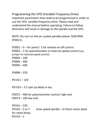
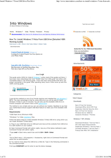
VARIABLEFREQUENCY DRIVEThe synchronous speed of an induction motor isprimarily a function of the number of poles andthe frequency:n 120 frequency# of poleste filters. Despite the non-ideal VFD problemswith clogging of the pump and sedimentation inpipe systems (due to low velocities) are more likely to occur when the speed of the pump is reduced.Pumping with variable frequency drives can beseparated into two cases. A variable continuous flow is required by theprocess. The normal way to control the flow isby throttling. The use of VFD control will, inall cases, lead to an energy reduction. VFD vs. on/off regulation. Variable speed driveis used to reduce losses whilst pumping. Theeffect of a VFD depends upon the system.Systems with a high percentage of friction lossesrelative to the static head are suitable for VFDoperation. More pure lift systems, on the otherhand, are not generally suitable for variableoperation. The frequency normally decreaseswhen the speed is reduced and there is a riskthat the pump will operate outside allowed operational range. A thorough system analysis hasto be performed in order to determine if variable speed control can be economically beneficial.Waste-water pumping is a typical applicationwhere VFD and on/off control have to be compared.For more information, see Flygt brochure‘‘Economical aspects of variable frequency drivesin pumping stations’’.[rpm]A slip between actual and synchronous speed isgenerated by the applied load torque. This slip isusually small, typically 1-3% of synchronous speed.A way to achieve a variable speed motor is to varythe frequency. Such a device is called a frequencyconverter. Frequency converters, also called variable speed drives, are usually installed to allow fora better process control and to save energy. Theusage of variable frequency drive (VFD) control inpump applications is becoming increasingly common. The cost of a VFD has decreased over theyears while the performance has improved. Amodern VFD is a compact, well-developed unitwhich is relatively easy to install.Unlike an old VFD, the modern version doesnot require as much power margin (de-rating)and so does not affect the induction motor to thesame extent, this is due to the fact that VFDswitching frequency is higher today. The highswitching frequency however, induces transientswhich can lead to other problems such as nuisancetripping of control equipment. This effect can beminimized by using shielded cables and appropria-BASIC PRINCIPLEOF A VFDIn theory the basic idea is simple, the process oftransforming the line frequency to a variable frequency is basically made in two steps.1. Rectify the sine voltage to a DC-voltage.2. Artificially recreate an AC-voltage with desiredfrequency. This is done by chopping the DC-voltage into small pulses approximating an ideal sinewave.A VFD consists basically of three blocks: the rectifier, the DC-link and the inverter.RECTIFIERDC-LINKINVERTERFig 1. Schematic functions of a VFD3M
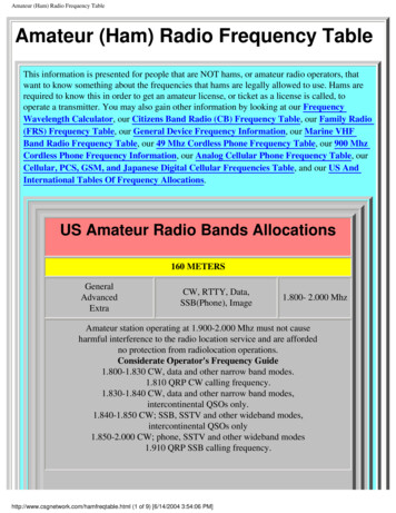
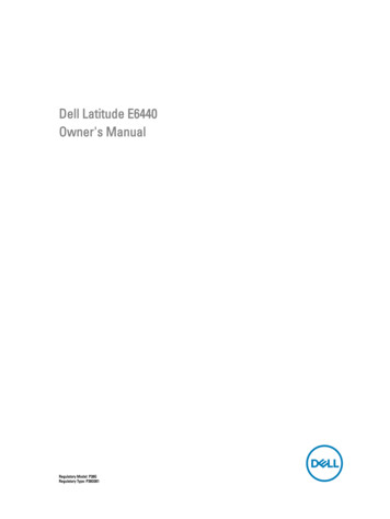
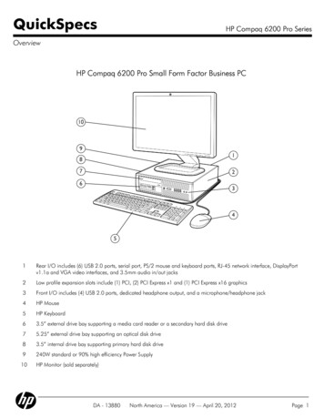
There are three different types of VFDs: VSI - Voltage Source Inverter, e.g. PWM. CSI - Current Source Inverter. Flux vector control.The CSI has a rough and simple design and is considered to be very reliable, but the output signalmeans a lot of noise. Furthermore the CSI induceshigh-voltage transients in the motor. The flux vector control is a more sophisticated type of VFDwhich is used in applications where the speedshould be controlled very precisely, e.g. papermills. This type is expensive and pump applications cannot take advantage of its benefits. Themost common type of VFD, and the one recommended by Flygt, is the PWM – Pulse WidthModulation.Fig 2. Schematic signal from a PWM-type VFDThe PWM-type VFD normally uses a constantvoltage which is pulsed with integrated bi-polarpower transistors (IGBT). The sine wave is generated by varying the width of the pulses. The frequency which the transistors are turned on and offby, is called switching frequency. The higher theswitching frequency, the better the reproductionof the ideal sine wave.SYSTEM Power drops toThe affinity laws state that the flow is proportional to impeller speed at a specific point on thepump curve. Head and NPSH are proportional tothe square of the speed, while the power is a cubical function of the speed. The hydraulic (pump)efficiency remains constant when the speed isreduced.Affinity laws: Hydraulic (pump) efficiency remains the same,74 %.All points on the pump curve will move alongsecond degree curves with constant efficiencytowards the origin of the co-ordinates when thefrequency is reduced.Ex. A centrifugal pump with nominal frequency50 Hz is running at reduced speed, 35 Hz. Thebest hydraulic (pump) efficiency point for thenominal curve is 74 % at a flow of 93 l/s and ahead of 9.3 m. Power in best efficiency point(BEP) is 11.5 kW. New BEP is calculated: Flow decreases proportionally to the frequency: Head is reduced toFig 3. Frequency-regulated pump curve.4
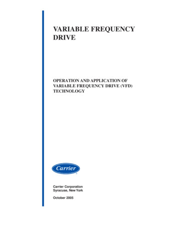
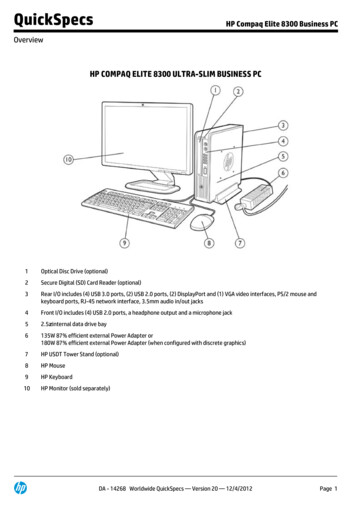
The actual duty point is always the intersectionbetween the pump curve and the system curve.The hydraulic (pump) efficiency in systems with astatic head will change when the frequency isreduced. The system curve for a system with a static head does not coincide with the constant efficiency curves. The duty point will move along thepump curve, towards the left side of the pumpand efficiency curves, (see fig 4 and fig 5).The system curve for a pure loss system willcoincide with a constant efficiency curve, the hydraulic (pump) efficiency will remain constantwhen the frequency is reduced.Ex. The same pump in the previous example isinstalled in a lift system with a static head of 6 m.The duty point for full speed is the same as BEP,93 l/s at 9.3 m (eff. 74 %) What happens to theduty point when the pump frequency is regulateddown to 35 Hz? Flow decreases to 26 l/s, (see fig 4). Head is reduced to 6.4 m, (see fig 4). Shaft power drops to 3.4 kW (see fig 5). Hydraulic (pump) efficiency is not constant,dropping to 50 % (see fig 5).It is worth noting that the pump stops deliveringflow at 32 Hz in this application.It is recommended, when selecting a pump forVFD duty, that it has its full speed duty point onthe right hand side of the BEP. This is due to thefact that the duty point moves towards the lefthand side of the efficiency curve when the speed isreduced. Thus, hydraulic (pump) efficiency initially will increase when the frequency is reduced,and the rapid efficiency drop on the curve will notoccur until the speed is reduced further.Some of Flygt’s pump curves are partially limited due to power or hydraulic limitations causingvibrations induced by re-circulation in the impeller. This will not disappear when the speed isreduced, and minimum allowed flow will be proportional to the frequency. The power reductionis dramatic when the frequency goes down, eventhough total efficiency drops. The power limitations disappear quickly.Fig 4. System duty-point movement for a lift systemand a pure loss system.Fig 5. System duty-point movement for a combined system anda pure loss system shown in an efficiency and power diagram.Fig 6. Change of upper and power limitationwhen frequency is reduced.5
The maximum allowed output power (nominalrated power) will decrease when frequency andinput voltage are reduced. See section ‘‘Motorcharacteristics’’ for more detailed informationregarding voltage control. The load torque(power) will however be reduced much faster. It isimportant when selecting a pump with an oversized impeller which cannot, due to power limitations, be run at nominal (e.g. 50 Hz) frequency tocompare the output power at desired max. frequency with the max. allowed output power atthe same frequency.There are two standard ways to control theVFDs when running several pumps with parallelconnection in the same system: separate and common control. Separate control means that onepump is running at reduced speed and the rest arerunning at full speed. With common VFD control,all pumps are running with reduced speed at thesame time. Separate VFD control is in generalFig 8. Separate VFD control.most economical, but there are cases where common control can be a better choice.The change of total efficiency when the speed isreduced is not only due to system duty pointmovement, even if it contributes to a major part.Motor and VFD efficiency will also be changedwhen the frequency is reduced.Fig 7. Common VFD control.MOTORCHARACTERISTICSThe characteristics of an electric motor will changewhen the frequency, and thus the speed, is reduced. The output torque from the motor is for anormal motor slip, a function of input voltage andfrequency.There are two standard ways to control the output voltage from a VFD. Votage that is proportio-nal to the frequency and voltage proportional tothe square of the frequency. The available motortorque remains constant when the frequency isreduced, if a VFD with an output voltage proportional to the frequency is used. Having voltageproportional to the square of the frequency implies that torque is proportional to the square of frequency.A pump represents a cubical load, the loadcurve is shown in fig 9. The diagram shows how6
frequency is somewhere in the middle of theright-hand flank, whereas the duty point at 20 Hzis almost at the end. This means that the slip willchange when the frequency is reduced. The efficiency of the motor is related to the slip, and theefficiency of the motor will drop even though thehydraulic (pump) efficiency remains constant. Themotor efficiency curve will also change when thefrequency is reduced. It can be seen from fig 9that the relative position of the duty point on theright flank is relatively constant when having thevoltage proportional to the square of the frequency. I.e. the slip and hence the motor efficiency willnot change so much. A voltage proportional to thesquare of the frequency is recommended for pumpapplications in order to maintain both motor efficiency and the correct magnetisation level.Fig 9. Motor duty-point movement.the duty point, the intersection between the motortorque curve and load curve, moves down on theright flank of the torque curve for U f when thefrequency is reduced. The duty point at nominalVFD INFLUENCE ONINDUCTION MOTORSput signal is looking more and more like an idealsine wave. This implies that a modern VFD withhigh switching frequency can run with a low or nopower margin whatsoever, while an old one mightneed a margin of 15%. Unfortunately the extensive work needed to developVFDs’ ability to reducelosses in the motor and in the VFD, tends to emphasize other problem areas. VFDs with highswitching frequency tend to be more aggressive onthe stator insulation. A high switching frequencyimplies short rise time for the pulses which leadsto steep voltage transients in the windings. Thesetransients stress the insulation material. Flygtrecommends reinforced stator insulation for voltages 500 V and above.This problem can also be solved partially byadding an output filter to the VFD. See section“Noise suppression” for more details.An induction motor feels most comfortable whenit is supplied from a pure sine voltage sourcewhich mostly is the case with a strong commercialsupply grid. In a perfect motor there are no harmonics in the flux and the losses are kept low.When a motor is connected to a VFD it will besupplied with a non-sinusoidal voltage, this signalis more like a chopped square voltage. A squareshaped signal contains all orders of harmonics.As these harmonics will induce additional heatlosses that may require the induction motor to bede-rated, a margin between maximum outputpower and nominal-rated output power is required. The required power margin depends upon theapplication and the supplied equipment. When indoubt contact the local Flygt engineering office fordetails.The performance of the VFDs has improvedover the years and is still improving, and the out-SIZING CRITERIAThe data needed to determine the correct size of aVFD are: Motor kVA rating. Nominal voltage Rated current Ratio max. torque/nom. torqueIf the ratio between peak torque and nominal torque, Tp/Tn, is greater than 2.9 it might be necessary to choose a larger VFD. There are basicallytwo reasons why a motor can have a ratio greaterthan 2.9:1. The motor has a high magnetisation level2. The motor has been de-rated.7
RUNNING ABOVENOMINAL FREQUENCYSometimes there is a desire to run the pump atfrequencies above the nominal commercial supplyfrequency in order to reach a duty point whichwould otherwise be impossible. Doing so calls forextra awareness. The shaft power of a pump willincrease with the cube of speed according to theaffinity laws. Ten percent over-speed will require33 % more output power. Roughly speaking thetemperature will increase by approx. 80%.There is however, a limit to what we can squeeze out of the motor at over-speed. Maximum torque of the motor will drop as a function 1/F whenrunning above nominal frequency. This is due tothe fact that the VFD output voltage has reachedits full value at nominal frequency and cannot befurther increased. The area above nominal frequency is denoted as the field weakening range.The motor will be overloaded and drop out if theVFD can’t support it with a voltage that corresponds to that needed by the torque. In reality theVFDs’ over-current protection will trip after ashort while if we try to run the pump too far intothe field-weakening range. Running above nominal frequency is not recommended, but if required, use the following guidelines: Check rated power. Shaft power will increaseto the power of three according to affinitylaws. Check that the VFD is dimensioned for the loadincrease. Current is higher than nominal ratedcurrent (for nominal frequency) in this case. Change ‘‘Base frequency’’ of the VFD. Base fre-quency is the frequency where the VFD outputvoltage is the same as supplied nominal line voltage. If possible, select a machine designed for ahigher frequency. When running a pump designed for 50 Hz operation above nominalspeed, select a 60 Hz motor.NPSH-required increases, according to the affinitylaws, when running above nominal frequency.Always check that NPSH-available is greater thanNPSH-required in order to avoid cavitation.Fig 10. Maximum torque as function of speedCOOLINGThere are four cooling systems available for aFlygt pump: Cooling by surrounding media, water/air. Integrated cooling. Water is pumped through acooling jacket with back vanes on the impeller.The water flows with rotation in the coolingjacket which surrounds the stator house, e.g.medium and large C pumps. Axial-flow cooling. The motor is cooled by thepumped media, the water flows along the outside of the stator house, e.g. Flygt’s B, PL andLL pumps. External cooling.The integrated cooling system of Flygt’s largerpumps has many advantages. One restriction however is that the pump must not run at too lowspeeds unless it’s working in clear water. Thecooling is adequate, but sediment may accumulateand the risk of clogging in the cooling system ishigher when the speed is reduced. When thepump is sped up again and retains nominal speed,the efficiency of the cooling system is lower andthe motor can overheat.The critical minimum speed is different for different pumps, but a rule of thumb is that noadverse effects are likely to occur for speeds high8
er than 35 Hz for 2- and 4-pole machines, and 40Hz for higher pole numbers. Another restriction isthat the speed of the pump must not be too lowwhen it’s started for the first time after service –or a longer stop. This is due to the fact that all airin the cooling jacket has to be evacuated.Contact the local Flygt office for detailed information regarding minimum and start-up speed forevacuating air in the cooling jacket.Axial-flow cooling efficiency decreases rapidlywhen the flow goes down. The cooling efficiencyis not a function of speed, it’s a function of flowand the flow is dependent upon the system characteristics. Axial-flow pumps are often installed inlift systems and are therefore not suitable for operation with variable speed drive.Pumps cooled with surrounding media andpumps with external cooling are generally notaffected by VFD duty.The thermo-contacts should always be connectedregardless of whether the pump is VFD-controlledor not.CLOGGINGIp w2Waste-water pumping stations are in general designed for peak flows which occur approx. 5 % orless of the time. Pumps operated on VFDs run atreduced speed almost all the time. Lower flowsresult in lower velocities in the sump and a higherrisk for sedimentation. Sizeable clusters of largeparticles may build up in the sump. Eventuallythey will break loose and may cause clogging inthe impeller. The risk of clogging is generally higher in dry installed pumps. Sedimentation maybuild up in the inlet pipe, large solid particles caneasily get stuck in the 90 inlet bend leading intothe pump.When running at reduced speeds, the availableenergy for the impeller to keep itself from clogging, decreases rapidly. Available energy in theimpeller is proportional to the square of speed.The available impeller energy will drop 75% whenthe speed is reduced from nominal speed to halfspeed (see equation).The distance from the leading edge of theimpeller or propeller blades to the point wherethe flow becomes turbulent, will increase when thepump is running at reduced speed. This fact increases the risk of catching long fibrous materialson the leading edge. The pump is less effective inT 2T EnergyWhereIp Polar moment of inertiaw speed [rad/s]carrying away solids and clogging materials, whenthe velocity of the liquid is decreased. Longfibrous materials are more likely to catch on vaneswhen the velocity of the pumped media is low.The rapid acceleration at start-up of on/off controlled pumps, effectively removes initial cloggingin the pump. There is also a natural back flushwhen the pump stops, which prevents clogging.VFD-controlled pumps are, as mentioned above,seldom running at full speed. They are often running continuously and cannot gain from the on/offcontrolled pumps’ benefits. This can be handledby adding a cleaning sequence 1-2 times per hour,where the pumps start and stop at full speed acouple of times. It is important that the rampingtime at start and stop is short.When running multiple pumps in continuousduty, it is possible that one particular pump handles the small flows and runs almost all the timewith reduced speed. The risk for clogging andsedimentation is higher for this pump. This can beavoided by alternation of the pumps.VIBRATIONSPumps running with variable frequency drives,excite a broader range of frequencies. The probability of exciting one of the system’s natural frequencies, increases when running pumps with variablespeed drives. This can lead to problems with vibrations and noise, especially in stations with dryinstalled pumps. If one of the system’s natural frequencies is in the duty range of the VFD, this fre-quency can be blocked in the VFD control unit.Most modern VFDs have this blocking function.Some of Flygt’s pump curves are dashed at lowflows (close to shut-off head). Running the pumpsin this area can cause vibration problems.See Flygt brochure “Design recommendationsfor pumping stations with dry installed submersible pumps” for more detailed information.9
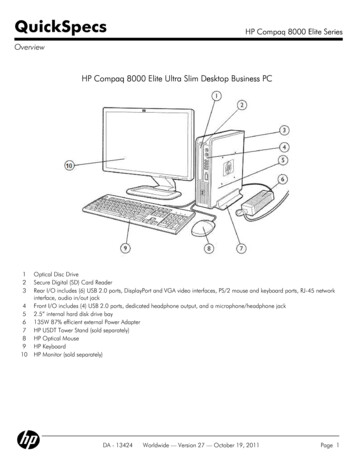
EMCEMC stands for Electromagnetic Compatibility. Itis the ability for electrical/electronic equipment tooperate without problems in an electromagneticenvironment. Likewise, the equipment must notdisturb or interfere with any other product orsystem. Electrical equipment should be immune tohigh-frequency and low-frequency phenomena.Interference from the surrounding area with equipment comes from transients, voltage fluctuation,high frequency signals, static electricity etc.The high frequency emission from a source shouldnot exceed a level which prevents other equipment to operate as intended. Interference to thesurrounding area from an electronic equipmentsuch as a VFD can be produced by very fastswitching components (triacs, IGBTs) in the frequency converters’ control system. The high-frequency interference can propagate by conductionand radiation.The EMC requirements must be followed whenoffering and selling both pumps and completesystems with control equipment on the Europeanmarket. All Flygt pumps are CE-marked accordingto the EMC-directive, and the VFD that goes withthe system should also be CE-marked. The interconnecting cable between the pump and the VFD,has to be shielded in order to make the VFD passthe EMC-tests.NOISE SUPPRESSIONPUMP/MIXERCONTROL SM3604680075Control cableVFD300 mmNSSHÖU./3E StFilterscreened power coresCommon power/monitoring cable(i.e. 3x2.5 3x2.5/3E 3x1.5 St partno.940937) to be kept as short as possible.Overview noise suppressionCABLEprovided in our pumps (e.g. 3140 and largepumps). The power cable and monitoring cableshould run in separate cable ducts with a distanceof at least 300 mm between them. The length ofthe cable should be kept as short as possible, andshould not in any case exceed 40 m.Shielded power and monitoring cables should beused wherever possible. The recommended shielded cable supplied by Flygt is the NSSHÖU heavyduty rubber cable. Contact the local Flygt officefor more information. Separate power and monitoring should be used wherever dual cable entry is10
An output filter can be placed on the output signalfrom the VFD. This filter reduces the noise in theoutput signal. A lower or no power margin (derating) can be acceptable, if this filter is includedin the installation. Problems with nuisance trippingare also reduced.INSTALLATIONCubicle connection.Power conductor screen twisted togetherand connectedto PE.Use a Green/Yellowshrink tube over theconductor.Earthing clampsCut the blue controlwire and isolate theend.Installation of monitor cables in electrical cabinet.Control wires:T1-blackT2-brownThe monitoring cables in the electrical cabinet andin the pump/mixer junction box, should be kept asfar away as possible from the power cables.Scrape off the paintunder earthing clamps, hinges and screws.FILTERSInterference from a variable frequency drive maycause nuisance tripping of monitoring equipmentand electronic sensors. This occurs when the pilotcable is in close proximity to the power leads. Thisnuisance tripping may be suppressed by connecting a suitable filter between the monitoring conductors (T1, T2) and ground (PE). The filtershould ideally be located in the pump/mixer junction box.Spray scraped partswith colour orTectyl.Pump-junction box.Power conductor screen twisted togetherand connected to PE.Use a Green/Yellowshrink tube over thescreen conductor.Installation guidelinesFilter installed in pump-junction box.11
893472 VFD Recommendations.02.02.Eng.2M.04.00 ITT FlygtRiksby tryck AB
FREQUENCY DRIVE BASIC PRINCIPLE OF A VFD In theory the basic idea is simple, the process of transforming the line frequency to a variable fre-quency is basically made in two steps. 1. Rectify the sine voltage to a DC-voltage. 2. Artificially recreate an AC-voltage with desired frequency. This is done by chopping the DC-volt-