Transcription
Optical Model of Fritted Glazing inWINDOWPrepared by: Simon Vidanovic, Christian J. Kohler,D. Charlie CurcijaLawrence Berkeley National Laboratory9/24/2012
Optical Modeling of Fritted GlazingPage 21. INTRODUCTIONFritted glazing (also known as “frits”) is a special type of glazing which consists of aglazing substrate (usually specular glass) and diffuse patterns on the glass, commonlyreferred to as frits. The frit layer consists of glass and in some cases colored pigmentsthat are melted to bond to the substrate surface. This process can easily be masked sothat a pattern of the fritted surface is created. Because of the presence of diffusematerial, the whole glazing layer is considered to be a complex glazing, which requiresa more sophisticated calculation of the glazing system optical properties , whichincorporates fritted glazing layer. These more complex calculations also require moredetailed optical data, because the incoming direction of solar radiation is no longerequal to the outgoing direction, which is the case in specular glazing layers. The opticaldata for each complex glazing layer is provided in four matrices, one for fronttransmittance, one for back transmittance, one for front reflectance and one for backreflectance. Each matrix has data for 145 incident directions and 145 outgoingdirections for each incident direction, therefore forming 145 x 145 matrix of data, or21,025 data points. These matrices are provided for each wavelength.In the case of a highly spectrally selective layer, which is characterized by 300wavelengths, the total amount of data is 4 x 21,025 x 300 or 215,230,000 data points.In comparison, specular glazing layer of the same spectral selectivity will have 300transmittances, 300 front reflectances and 300 back reflectances, for a total of 900 datapoints. Note that for a specular glazing layer, only one set of transmittance data isneeded, as front and back transmittances in specular transmission are identical.The WINDOW software, developed by Lawrence Berkeley National Laboratory,implements calculations for fritted glazing using the matrix data discussed above. InWINDOW, spectral data for fritted glazing is stored in the WINDOW database in a tablecalled SpectralData. In order to generate spectral data for a fritted glazing layer,measured optical data from the frit substrate glazing layer without the frit and from thefrit substrate with the frit covering are combined using special algorithms, called “Frittedglazing composition”, detailed in this report. Fritted glazing composition opticalcalculations use a two layer optical model. Data for each layer is stored in a database.First layer is for substrate data, second layer is for frits. However, frits can have diffuseand specular portion. Both diffuse and specular portion of frits are obtained byimporting data from two different files (one for front side and one for back sidemeasurements), for a total of four individual optical data files.Columns of interest stored in SpectralData table are: WavelengthTRfRbTb
Optical Modeling of Fritted GlazingPage 3This document describes algorithms and procedures for fritted glazing compositionoptical calculations.2. OPTICAL DATAWhen loading spectral data for frits, the following arrays are used to store the data inthe program: taRfFritSpectralDataRbFritSpectralWLThe introduction of transmittance back is necessary since unlike for specular glazings,the transmittance does not have to be identical from the front and the back. All thesematrices are three dimensional with the following dimensions:1. (Glazing) Layer2. Component3. Index(Glazing) Layer is used to denote fritted glazing layer position in an IGU. For example,if fritted glazing layer is glazing layer 2 in an IGU, then (Glazing) Layer index will beequal to 1 (note that numbering starts from zero).Component part is used to store layers data representing Frit layer. Since there arethree layers used to represent one Frit, there will be three components stored in thesearrays:Component 0 – Substrate dataComponent 1 – Specular dataComponent 2 – Diffuse dataIndex is used to represent data for each wavelength2.1 BSDF Data ModelEach fritted glazing layer has its optical data stored in Bi-Directional ScatteringFunction, or BSDF format. BSDF are matrices of transmittance and reflectance, whereeach matrix contains columns of incident directions and rows of outgoing directions. Atthe maximum, BSDF is 145 x 145 matrix, corresponding to the 145 incident and 145outgoing directions (solid angles). For smaller angular basis, the number of directions isreduced. Currently we have half basis (72 x 72 matrix) and quarter basis (36 x 36matrix). Half and quarter basis may be used in calculations for improved speed, but theoptical data for a layer is still stored in full 145 x 145 matrix. One BSDF Matrix iscreated for each wavelength. The number of wavelengths and BSDF directions isspecified in WINDOW- Preferences- Optical Calcs screen (see Figure 1).
Optical Modeling of Fritted GlazingPage 4Figure 1: Options in “Optical Calcs” Tab Under “Preferences” ScreenOptical calculations in WINDOW, using Matrix calculation approach (mandatory forscattering glazing layers or shading devices) can be done for different wavelengthranges and for different angular bases definitions, as specified in Optical CalcsPreferences. Since frits are considered non-specular (i.e., diffuse) glazing layers, thematrix calculations will be performed independent of the setting for “Use matrix methodfor specular systems (glazing systems without shading devices”.2.2 Specular PropertiesMatrices for specular layer will have zero values, except for the values on the diagonal.The diagonal values will be calculated by using following equation:Eq.1Whererepresents the BSDF value for transmittance in the i-th direction,represents the solid angle partition for i-th direction andis transmittance for aspecific wavelength (read from the spectral data tables) and adjusted for specific
Optical Modeling of Fritted GlazingPage 5angular dependence. Note that Eq.1Eq.1 is valid for back and front transmittance aswell as for front and back reflectance. Matrix presentation of Eq.1Eq.1 is:Eq.22.3 Fritted Glazing Composition Optical CalculationsFritted glazing composition optical calculations consist of the following steps:1.2.3.4.5.Specular optical properties of the frit layer readoutDiffuse optical properties of the frit layer readoutCreate resultant frit layer matrix from specular and diffuse optical propertiesSubstrate optical properties readoutCreate fritted glazing BSDF by area weightingAfter performing above steps transmittance and reflectance (front and back) BSDFmatrices (i.e., BTDFF, BTDFB, BRDFF, BRDFB) are created and are ready to beincorporated into the calculation of the glazing system, that may involve one or morespecular glazing layers.2.3.1 Specular Optical Properties of the Frit LayerSpecular optical properties are stored in a diagonal matrix, as described in section 2.2.Note that all four matrices are stored using the same diagonal matrix form.2.3.2 Diffuse Optical Properties of the Frit LayerFor diffuse portion of the BSDF there is no angular dependence. This means thattransmittance and reflectance is uniform and identical for all angles and is onlywavelength -dependent. The values on the diagonal of this matrix are not used in thecreation of the resultant matrix, and can be ignored.Note: Because specular optical data is measured by subtracting diffuse from totalradiation, where diffuse radiation is measured by opening port in an integrating sphere,the specular component intrinsically includes diffuse portion in the specular direction(See Section 2.6).
Optical Modeling of Fritted GlazingPage 6Eq.3Eq.3Eq.3 is valid for front and back transmittance as well as for front and backreflectance.2.3.3 Frit Layer Optical MatrixThe resultant matrices of optical properties for the frit layer are created by addingspecular and diffuse matrices. The resultant matrix contains terms in a diagonal whichare equal to specular values, while rest of matrix is filled with the diffuse part.Eq.4And again, this matrix is also valid for reflectance.2.3.4 Substrate Optical PropertiesFritted glazing substrate data have the same format as the specular portion of the fritlayer (Section 2.2). Only diagonal terms are non-zero.2.3.5 Final Fritted Glazing Optical PropertiesSubstrate matrix is added to frit layer optical matrix (see Section 2.3.3) by weightingarea of the frit coverage. If frit layer matrix is marked asand substratematrix is marked asthen final fritted glazing BSDF is created using followingequation:Eq.5Where FritCoverage is number between 0 and 1 and denotes area fraction of fritcoverage (i.e., 0.2 is 20% frit coverage, 0.5 is 50% frit coverage, etc.).2.4 Angular DependenceEach term in the diagonal of the specular matrices correspond to an optical property ata given incidence angle. Since specular properties are only dependent on the overallincidence angle, without the consideration of solar azimuth, the only angulardependence is given with respect to incidence angle . Angular dependence for
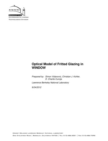
Optical Modeling of Fritted GlazingPage 7specular glazing is not measured, but is rather calculated. Calculation details are givenin Reference [1] and will not be repeated here.2.5 Hemispherical TransmittanceHemispherical transmittance is an integrated property at the outgoing direction,representing overall optical properties for each incidence angle (i.e., each fritted glazingwill have 145 hemispherical data points for each optical property (i.e., 145Transmittances, 145 Reflectances). The hemispherical transmittance is calculated foreach incident direction by using the following equation:Eq.6Whereis transmittance between incoming direction “i” and outgoing direction “j”, θj isangle between surface normal and direction “j”, N is number of outgoing directions andboth integrations in Eq.6Eq.6 are performed over outgoing direction.2.5.1 Solid Angle TransformationIn order to calculate integration given by Eq.6Eq.6, spherical coordinate system is used.In order to do integration in spherical coordinate system, infinitesimal angle dω needs tobe transferred into spherical coordinate system. Since all outgoing rays are covered byoutgoing half-sphere, integration of solid angle over half-sphere should be equal to 1.Therefore, we can calculate sold angle by simple division of dA and A:Eq.7Where A is area of half-sphere while dA is area of infinitesimal surface covered by solidangle dω.
Optical Modeling of Fritted GlazingPage 8Figure 2: Spherical CoordinatesArea of surface dA is calculated by following equation:Eq.8and since half-sphere surface is equal to 2πr2, Eq.7Eq.7 becomes:Eq.92.5.2 Hemispherical Transmittance IntegrationIntegration of Eq.6Eq.6 can be performed in two parts: nominator and denominator.Integration over denominator is fairly simple and it can be represented with the followingequation:Eq.10Substituting back into Eq.6Eq.6 and integrating over direction “j”:Eq.11then replacingwith Eq.9Eq.9 and performing both integrations, the followingequation is obtained:
Optical Modeling of Fritted GlazingPage 9Eq.12whereand.Introducing lambda coefficient as:Eq.13then Eq.12Eq.12 can be written as:Eq.14It is also noteworthy that following equation is valid:Eq.152.6 Spectral Data MeasurementsThere are two types of measurements taken from the samples. The first measurementis performed over the closed sphere as shown in Figure 3 which we will call totaltransmittance (Ttotal). In second measurement, sphere is open at direction normal to thesample (see Figure 4), which is used to let the specular portion of incident radiation toescape, this providing diffuse transmittance portion (Tdiff).Figure 3: Total Transmittance Measurement
Optical Modeling of Fritted GlazingPage 10Figure 4: Diffuse Transmittance MeasurementDifference between measured total transmittance and diffuse transmittance is speculartransmittance:Eq.16Note that while Eq.16Eq.16 is true for each incoming direction, measurement is done fornormal incident direction or i 1.T1,total, and T1,diff are measured in spectrophotometer and are reported as a result ofmeasurement for each wavelength. If we consider how these quantities are calculatedby the internal instrument’s software, we can prove that their difference is equal to themembers of diagonal component in a specular matrix (see Section 2.2). The followingformulas are applicable to these two quantities:Eq.17while for diffuse measurement:Eq.18which leads to the equation for specular transmittance:Eq.19From which:Eq.20
Optical Modeling of Fritted GlazingPage 11Eq.21and the rest ofare diagonal elements in a specular matrix.Note that value T1,specular in Eq.20Eq.20 is measured for normal incidence and thereforeequation can be applied only to. For specular samples, normal incidencemeasurement is usually the only measurement done. For other angles of incidence,formulas are used that correlate normal to off normal incidence angles (See Reference[1]). It is also possible to measure at different angles of incidence, in which case valuesdo not need to be correlated.The following set of equations details elements of diffuse matrix,Eq.18Eq.18 for any incidence direction “i”:. RewritingEq.22Eq.23where Ti,diff is angular dependent.3. REFERENCES[1] WINDOW 4.0: Documentation of Calculation Procedures, E.U. Finlayson, D.K.Arasteh, C. Huizenga, M.D. Rubin, and M. S. Reily, LBL-33943, UC-350, July 1993.
Optical Modeling of Fritted Glazing Page 2 1. INTRODUCTION Fritted glazing (also known as "frits") is a special type of glazing which consists of a . data for each complex glazing layer is provided in four matrices, one for front . In order to calculate integration given by Eq.6Eq.6, spherical coordinate system is used.