Transcription
cryptographyArticleQUARC: Quantum Research Cubesat — AConstellation for Quantum CommunicationLuca Mazzarella1, ,† , Christopher Lowe 2 , David Lowndes 3 , Siddarth Koduru Joshi 3 ,Steve Greenland 4 , Doug McNeil 4 , Cassandra Mercury 4 , Malcolm Macdonald 2 , John Rarity 3and Daniel Kuan Li Oi 11234*†SUPA Department of Physics, University of Strathclyde, Glasgow G4 0NG, UK;lucamazzarel@gmail.com (L.M.); daniel.oi@strath.ac.uk (D.K.L.O.)Department of Mechanical and Aerospace Engineering, University of Strathclyde, Level 8, James WeirBuilding, 75 Montrose Street, Glasgow G1 1XJ, UK; christopher.lowe@strath.ac.uk (C.L.);malcolm.macdonald.102@strath.ac.uk (M.M.)Quantum Engineering Technology Labs, H. H. Wills Physics Laboratory & Department of Electrical andElectronic Engineering, University of Bristol, Merchant Venturers Building, Woodland Road,Bristol BS8 1UB, UK; david.lowndes@ bristol.ac.uk (D.L.); sk.Joshi@bristol.ac.uk (S.K.J.);john.rarity@bristol.ac.uk (J.R.)Craft Prospect ltd. Tontine building, 20 Trongate, Glasgow G1 5ES, UK; steve@craftprospect.com (S.G.);doug@craftprospect.com (D.M.); cassandra@craftprospect.com (C.M.)Correspondence: luca.mazzarella@jpl.nasa.govCurrent address: Jet Propulsion Laboratory, California Institute of Technology, 4800 Oak Grove Drive,MS 298-102, 91109 Pasadena, CA, USAReceived: 23 December 2019; Accepted: 21 February 2020; Published: 27 February 2020Abstract: Quantum key distribution (QKD) offers future proof security based on fundamental lawsof physics. Long-distance QKD spanning regions such as the United Kingdom (UK) may employ aconstellation of satellites. Small satellites, CubeSats in particular, in low Earth orbit are a relativelylow-cost alternative to traditional, large platforms. They allow the deployment of a large number ofspacecrafts, ensuring greater coverage and mitigating some of the risk associated with availabilitydue to cloud cover. We present our mission analysis showing how a constellation comprising 15low-cost 6U CubeSats can be used to form a secure communication backbone for ground-based andmetropolitan networks across the UK. We have estimated the monthly key rates at 43 sites across theUK, incorporating local meteorological data, atmospheric channel modelling and orbital parameters.We have optimized the constellation topology for rapid revisit and thus low-latency key distribution.Keywords: SatQKD; CubeSats; satellite constellations.1. IntroductionEncryption is vital for securing the transmission of personal, commercial and governmentaldata. The rapid development of quantum computation threatens the underpinnings of current publickey cryptographic methods, most notably the RSA (Rivest–Shamir–Adelmann) cryptosystem [1],that are the basis of the internet. Hence, there is the need for the development of “quantum-safe”communication methods that can provide forward security for critical information. We also note thedevelopment of “post-quantum cryptography” [2] that seeks replacement public key algorithms thatare resistant to attack by quantum and classical computers. Quantum key distribution (QKD) has beenproposed as a solution that allows two distant parties—traditionally named Alice and Bob—to establisha joint secret key of which the security is dependent not on computational complexity assumptionsbut on the laws of quantum physics. There has been significant effort toward its theoretical andexperimental development [3–6] over more than three decades, with commercial fibre-based systemsCryptography 2020, 4, 7; l/cryptography
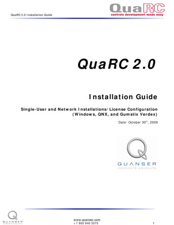
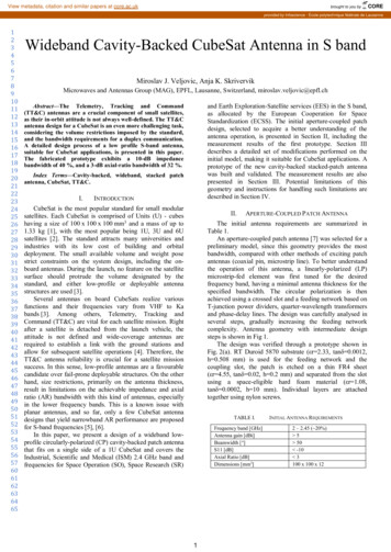
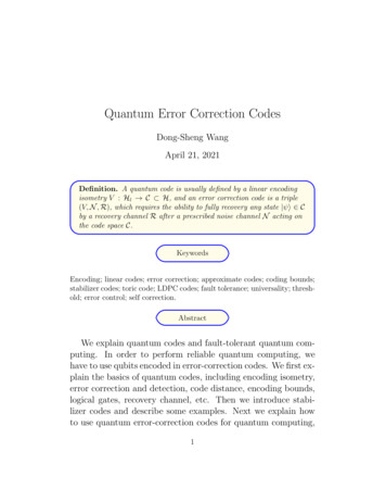
Cryptography 2020, 4, 72 of 27now commercially available. However, fibre losses scale exponentially with distance, greatly restrictingthe range of terrestrial QKD. Conventional optical repeaters cannot be used with QKD [7–9] sincequantum information cannot be perfectly and deterministically copied [10–12] and practical quantummemories are still a long-term prospect. Satellites are currently the only viable option for extendingQKD communication ranges beyond distances greater than a few hundred kilometers [13–17] and thusfor enabling the global quantum internet [18].In this article, we present an overview of the quantum research CubeSat (QUARC) spacemission and evaluate the feasibility of providing a secure satellite quantum key distribution (SatQKD)service to the UK via a constellation of CubeSats. Another recent work on satellite constellationsfor QKD networks but with different aims can be found in Reference [19]. Recently, Satellitequantum communication has witnessed an unprecedented growth including proof-of-principleexperiments [20–26], quantum mechanics fundamental tests [27,28], and the launch and operationof a QKD satellite [29–31]. These groundbreaking results have spurred an international space raceinvolving university consortia, national agencies and private companies, e.g., QKDSat (ArQit) [32],QUARTZ (SES) [33], QEYSSAT (Canada) [34], UK–Singapore Bilateral (RAL Space—CQT) [35],QUBE (Deutsches Zentrum für Luft- und Raumfahrt (DLR) German Universities) [36], NANOBOB(Austria–France) [37] and IOD-6/ROKS (UK) [38]. Many of these efforts focus on satellites belongingto the domain of large and complex platforms, and little research has been carried out so far regardingQKD performance evaluation using smaller satellites. On the other hand, Small Satellites (SmallSats)and especially the popular CubeSat standard have been in the spotlight for their potential to delivermeaningful communication volumes at a significantly reduced price and complexity. Operationally,they represent a path finder option for the deployment of large constellations offering rapid revisitand therefore greater coverage than a single large spacecraft [39,40].The objective of the QUARC space mission is to provide a QKD service to a specific region:the UK. We identify relationships between satellite constellation topology, the atmospheric channeland historical weather data and estimate key rates over 43 ground stations (gateways) uniformlydistributed across the UK (Figure 1) serviced by a constellation of 15 satellites. These gateway locationscannot be connected currently via the installed fiber network, and they have been defined specifically inorder to gain an understanding of how communication performance varies across different regions atdifferent times throughout the year. The aim is not to satisfy a particular revisit/coverage requirementbut to offer a generalised performance metric from which performance can be scaled by the numberand location of gateways and by the number and distribution of satellites in the constellation. Moresatellites result in a greater level of expected coverage and secure key, while more gateways resultin a higher probability of contact being made and a smaller amount of key data being received ateach individual gateway. Here, we have chosen not to focus on the key management and schedulingproblems but we refer the reader to recent works on these topics [41,42].
Cryptography 2020, 4, 73 of 27Figure 1. Distribution of 43 hypothetical gateways (red dots) distributed across the UK region.The number of keys that can be distributed between the constellation and each gatewaythroughout the year is evaluated via simulation that incorporates effects from cloud cover,sunrise/sunset, and various sources of losses and spurious counts in order to consider the impact ofthe changing seasons and latitude. The best case scenario is found to be represented by the southeastEngland gateway where 300 kbit/night/satellite of key can be exchanged during August, while theworst case is represented by the northeast islands of Scotland, where no key can be distributed; this isdue to the constraint of nighttime operations that we have assumed for the purposes of the analysis.We assume a conservative level of system performance and that daytime background light wouldresult in excessive spurious counts, curtailing operations. We also conservatively assume that QKDoperations are not possible in twilight or dusk conditions. In practice, some nonzero key rates may bepossible with small levels of background light and a more detailed simulation incorporating site-levelbackground light and astronomical data, e.g., position of the moon, is in development. SatQKDsystems that can operate in daytime are currently under development by various groups [43–46] butnot yet fully demonstrated in orbit. On the other hand, when the constellation is required to distributekeys not only to a single gateway but also to all gateways, the best case scenario secret key volumedecreases to 160 kbit/night/satellite, which is also in southeast England. Our results indicate thata CubeSat constellation has the potential to deliver a meaningful amount of secret key for scenariosrequiring small-volume, highly secure communication via quantum-resistant symmetric key cipherslike Advanced Encryption Standard (AES) [47]. We have also carried out preliminary system designand tests of the payload acquisition, pointing and tracking (APT) system, which is a vital subsystemfor long-distance free-space QKD; these will be detailed in a separate paper.The rest of this work is structured as follows: In Section 2, we outline the payload design, inparticular the acquisition pointing and tracking system. In Section 3, we describe the model for thequantum channel. In Section 4, we present the mission design and discuss the orbital choice for the
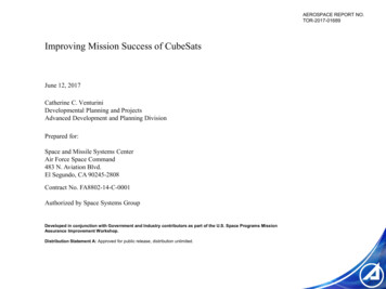
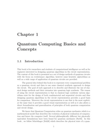
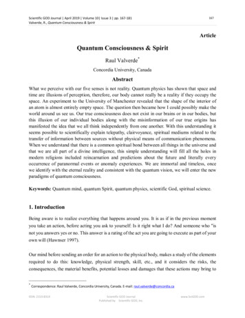
Cryptography 2020, 4, 74 of 27satellite constellation. In Section 5, we model the key exchange between the constellation and the setof gateways. Section 6 is devoted to the presentation of the mission performance. Finally, this paperconcludes with Section 7.2. Payload Design and System OutlineThis section gives a brief description of the QKD payload and subsystems used in the missionanalysis. A concept outline for the 6U CubeSat is shown in Figure 2. Such a payload has similarityto free-space optical communication payloads in development for nanosatellite missions [36,37,48]and handheld devices [49,50]. SatQKD can be divided into two main types: untrusted and trustednode [13]. Untrusted node SatQKD ensures verifiable security between two grounds stations viaBell test measurements without any assumption of the security of the satellite itself. This requiressimultaneous links between the satellite and the two ground stations, difficult to achieve with high keyrates. On the other hand, the trusted node paradigm assumes the satellite to be outside the domainof influence of an eavesdropper. For near-term realisation of SatQKD, the trusted node scenariois thus the most feasible. Trusted node SatQKD can be realised using the spacecraft as a receiver(uplink (UL) configuration) or as a transmitter (downlink (DL) configuration). A DL configurationrequires the development of a space-qualified optical assembly for precise pointing of the order offew µrad and quantum sources driven by quantum random number generators [39,40]. The ULconfiguration requires a less complicated payload comprising single photon detectors but wouldalso require a larger telescope compared to DL [37,48]. However, in this configuration, the upwardbeam encounters turbulence early during its path, leading to larger path deviations (the so-calledshower curtain effect) and therefore higher losses, on the order of 20 dB greater with respect to the DLconfiguration [13,17,51,52]. In this work, we therefore focus attention on the DL scenario.
Cryptography 2020, 4, 75 of 27Figure 2. Layout of 6U CubeSat: Approximately 3U (2.5 litres) of volume is reserved for the platformsystems including the electrical power system (EPS), communications (COMMS), on-board computer(OBC) and attitude determination and control system (ADCS). The ADCS incorporates a star tracker(shown separately) to provide sub-0.25 coarse pointing and is located on the opposite face to thetransmission aperture. The transmission telescope occupies 1U, the source and APT system occupy1.5U and the payload electronics occupy 0.5U. An S-band antenna is located on the same face as thetransmission telescope to allow high-speed radio frequency (RF) communications during the QKDpass for real-time data post-processing. The satellite bus would also include deployable solar panels torecharge on-board batteries that would provide sufficient power for repeated QKD operations duringthe eclipse phase of the orbit. Appropriate 6U CubeSat buses are available from commercial providerssuch as Blue Canyon Technologies (www.bluecanyontech.com), Endurosat (www.endurosat.com),GomSpace (gomspace.com), Innovative Solutions In Space (www.isispace.nl) and AAC Clyde Space(www.aac-clyde.space).Quantum Source: QKD requires the ability to send extremely faint pulses of light at a high repetitionrate and with a polarization randomly selected from a set of non-orthogonal signal states. This canbe achieved by combining multiple differently polarized sources or by modulating the polarizationof a single source. Currently, we plan to use multiple polarized LEDs (extinction 1000:1) combinedwith a single-mode fibre to remove spatial information. LEDs have a wide spectrum, and thereforewith appropriate filtering, they are resilient to mismatches in wavelengths between the LEDs. Recentadvances in integrated optics could also be leveraged using interferometers to modulate light and2D grating couplers to generate the polarization states from a single source [53]. An integratedplatform would be smaller but would require additional hardware to monitor the output. Suchsources have been previously developed with small size, weight and power (SWaP) envelopes of theorders of 10 4 m3 , 10 1 kg and 1 W. They can be made to be monolithic, solid-state devices withfurther miniaturisation possible through integrated optics fabrication [54,55]; hence, the source canbe accommodated in 1U. The main issues will be wavelength matching between different emitters toprevent side-channel leakage, modest temperature stability and reliability in the space environment;the latter is still to be proven [56].For the source wavelength, we have chosen 808 nm for ease of laser diode selection, atmospherictransmission and low background light during night operations due to atmospheric scattering ofmoonlight and OH recombination in the upper atmosphere [57]. We assume a pulse repetition rateof 100 MHz, comparable with QUESS/Micius [29]) and quite modest compared to what is currentlyachievable in fiber [58].An important aspect of such a source is a supply of truly random and securely generated bits. Fora 2-Decoy State Protocol, 4 bits per pulse need to be generated at a rate of 400 Mbps, leading to several
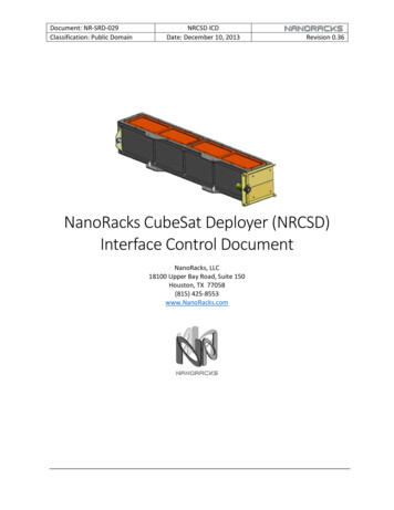
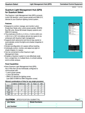
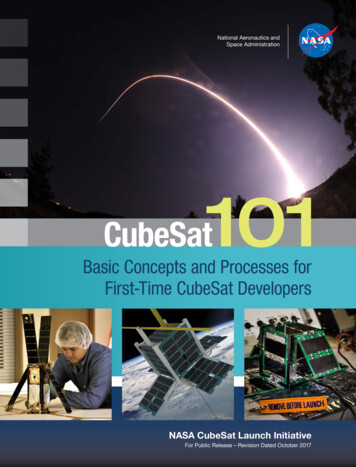
Cryptography 2020, 4, 76 of 27tens of gigabytes of random data required for a single pass. For protocols requiring biased basis andsignal choices, this will increase the required generation rate. High speed quantum random numbergenerators (QRNGs) with suitable SWaP requirements exist, allowing real-time on-the-fly provisionthough in-orbit demonstration and validation are still required [59]. A QKD protocol also requiresbidirectional classical communication between Alice and Bob for reconciliation, error correction andprivacy amplification which can be performed by RF communications over public channels.Acquisition, Pointing and Tracking System: In low earth orbit (LEO), the transmission range variesfrom a few hundred km at zenith up to about 2000 km at low elevations. It is therefore crucial toachieve a pointing accuracy of the order of micro-radians in order to mitigate channel losses. In oursystem, pointing is achieved in two stages: coarse pointing and fine pointing.The coarse-pointing stage is provided by pointing the body of the satellite via ADCS and hencethe rigidly mounted telescope. Fine pointing is provided by a closed-loop beam steering system usinga beacon tracking camera (BTC) and a MEMS micromirror (MM) (Figure 3). A MM is a mirror thatcan be tilted independently over the x and y axes. We have chosen a Mirrorcle S40069 [60] that has a5-mm diameter and can be mechanically tilted to up 5 (optical tilt 10 ) with step of 1.3 µrad (thetransmission telescope magnification improves this precision by a factor of 30) and is controlled usinga software proportional-integral-differential (PID) controller. The quantum signal and both UL andDL beacons are co-aligned on the main boresight of the telescope through in-orbit calibration; theseare steered by the MM driven by the output of the BTC. A DL beacon is sent at 905 nm and is coupledinto the beam path by a short-pass dichroic mirror, co-aligned with the 808-nm quantum signal. TheDL beacon also carries a clock signal synchronised with the 808-nm quantum signal pulses, allowingthe optical ground station (OGS) to perform coincidence matching and background event rejection.The UL beacon—chosen to be at 850 nm—is picked out of the beam path by a short-pass dichroic. Theimage of the UL beacon is focused onto the UL Beacon Camera which is read out at up to 1 kHz in theregion-of-interest mode. Preliminary testing indicates that µrad pointing precision is achievablewith modest UL beacon power with careful optimisation of the centroiding algorithm DSourceFigure 3. Downlink fine-pointing system schematic: A 90-mm telescope collects light from a beaconon the optical ground station (OGS) and produces a collimated 3-mm beam that reflects off amicro-electromechanical system (MEMS) mirror that provides beam steering. The beacon light isseparated on a dichroic beamsplitter and is directed towards the beacon camera. The beacon spotposition on the sensor is used as a feedback signal to the MEMS mirror to correct errors in satellitepointing. The QKD source is coupled into the other arm of the beamsplitter so that the QKD andbeacon beams are nominally colinear and counterpropagating. Due to the rapid transverse motionof the satellite and the small transmitted beam divergence, a point ahead correction is required. TheDL beacon has been omitted for clarity. A second dichroic mirror combines the DL beacon with theoutgoing quantum signal. This allows the OGS to track the satellite as well as to convey precise timingand synchronisation information required to pick out the faint quantum signals from backgroundnoise.
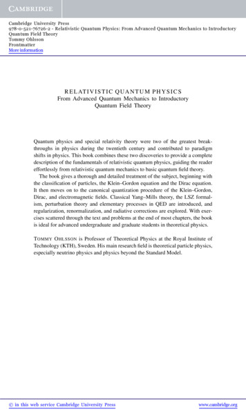
Cryptography 2020, 4, 77 of 27The field of view (FoV) of the UL beacon camera is 5.5 mrad, compared with the telescope FoV17.5 mrad (Figure 4). Hence, it is simple to scan the entire telescope FoV using the MM beam steeringfunction for initial acquisition of the UL beacon. In this mode, the beacon spot is simply required to beguided close to the set point; this can be achieved in the time or order of 1 second. After this has beenachieved, only a small fraction of the camera sensor needs to be read, which speeds up the trackingloop by up to an order of magnitude.Figure 4. Fields of view: The telescope has a 0.25 4.36 mrad half FoV to match the coarse-pointing performance of a moderate ADCS system. The effective MM steerable range is 1030 0.33 . The FoVof the uplink beacon camera is 1 mrad as this is restricted by packaging constraints of the optical pathand component sizes; in principle, this could be up to 5 based on the UL beacon pixel array size. TheDL beacon has a divergence of 100 µrad, wider than the 20-µrad beam width of the quantum signal toensure that timing and synchronisation are still maintained in the event of temporary fine-pointingexcursion beyond the quantum beam width.Once UL beacon lock has been achieved by the fine-pointing mechanism, the deviation of the MMfrom the neutral position represents a boresight error and this can be fed back to the ADCS to improvecoarse pointing. This would allow the reduction of the required telescope FoV that is diffractionlimited; degraded performance of the outer field is acceptable for initial UL beacon acquisition, andthe use the fine-pointing feedback signal to the ADCS would greatly reduce the coarse-pointing errorso that quantum transmission would be restricted to a central region of the telescope FoV.The centroid position of the beacon is compared with a set-point. The set-point includesa point-ahead offset that depends on the transverse velocity of the satellite with respect to theOGS-satellite line-of-sight (LoS) that can reach a maximum of 50 µrad; this can precomputed asa function of time during the pass. A correction signal is sent to the MM driver that performs beamsteering so that the UL beacon spot is brought towards the set-point. Our preliminary implementationshows that the APT systems should occupy no more that 1U.Transmission optics: The transmission optics is specified as a 30 telescope of 90-mm diameter(Figure 5). The exit pupil position, where the MM will be placed (back-focus position), and thesize of the rear element should be compatible with the APT system geometry. The telescope shouldbe athermal for the range of temperatures of operation, nominally 20 C to 30 C, and should beachromatic over the wavelength range 800 nm to 850 nm. The optics should be polarisation insensitivealong the (transmissive) quantum signal beam path. A maximum volume of 2U is specified for the
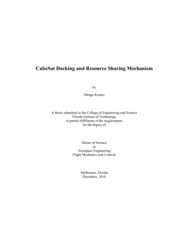
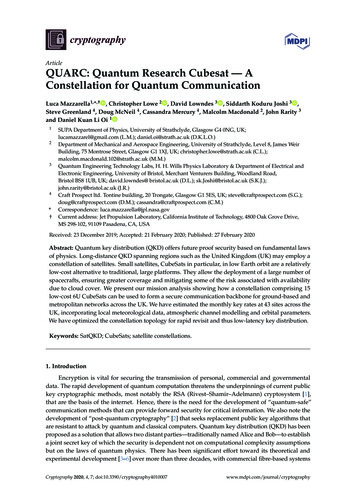
Cryptography 2020, 4, 78 of 27transmission optics; this should be achievable with a reflective or catadioptric design, and its massshould be below 2kg.Figure 5. Preliminary payload telescope and beacon camera optical design concept: The 90-mmdiameter 30 afocal catadioptric telescope has diffraction-limited performance between 800–850 nmover a field of view of 0.25 and is 75 mm long. The MM (fast steering mirror) is located at the exitpupil to the rear of the telescope. Incoming uplink beacon light is directed to the uplink beacon cameravia a fold mirror, dichroic mirrors and a focusing lens. The dichroic mirrors combine the outgoingquantum signal and downlink beacon (neither are shown).In summary, a 6U CubeSat is proposed for the QUARC mission, which comprises approximately2U of volume for the APT and source, 2U of volume for the telescope system and 2U of volume forthe supporting platform systems. The supporting systems not only must carry out housekeepingoperations such as power management, command and data handling, and telecommunications totraditional ground stations but also must take care of advanced functions such as coarse pointing viaan ADCS and orbit station-keeping using a propulsion system. Orbit station keeping is required tomaintain precise Earth and Sun synchronisms, without which the repeat ground track characteristicswould quickly be lost, sacrificing targeted coverage over the chosen region. This will be furtherdiscussed in Section 4.3. Channel AnalysisLosses as well as spurious counts are detrimental for the final secret key rate as it makes thequantum state less distinguishable [11,61]. In this section, we are going to model the channel betweenthe satellite and the OGS and to review the source of losses and background counts. The physicalscenario is summarized in Figure 6.
Cryptography 2020, 4, 79 of 27CubeSatPointing error pAtmosphere latexit sha1 base64 "zI8EaM9doqo5COXOhg47aNzOkd8 " AAAB/3icbVA9TwJBFNzzE88v1NJmIzGxIndooiXRxhIT AOrqTLwTFYAa IFGCBCIzkI4cTMzeO7UcLFCZZJrVQMz4ulu4tC Xo 7A /gGIzOVAA /latexit Diffractiondsat(ϑ)OGSReceiving stage Optical lossesDetection lossesSpurious countsFigure 6. Quantum channel representation: In modelling the quantum channel, we have consideredFigure 13. CQuCoMConceptof Operations.is a theproposalto perform orbitvarious sourceof losses, spuriouscounts and sourceTheerrors,CQuCoMall of which decreasefinal secret keydistribution ofrate.quantum keys and entanglement. A 6 U CubeSat would be deployed from thestar sent fromthe optical3.1. ChannelLosses ground station allows the CubeSat to acquire and track the site locatdesigneItaly as it passescloseLossesby. Aplatformpointingand betweenactive satelliteoptics is designedDiffraction:duecombinationto diffraction of theoftransmittedbeamover the distanceand OGS areby far thethemostopticalimportant groundlosses. The distancedependsthe orbital altitudeand on the as part ofquantum sourcetowardsstation.Twoonlaunchesare proposedelevation of the satellite, as seen by the OGS. In this proposed mission, we consider a circular orbituses a weak coherent pulse source to test the tracking and pointing system and for BB84with an altitude of 574 km; the distance between the satellite and the OGS will thus range between 574entangled km—atsourcethat wouldallow fundamentaltestsof ofmechanics as well as E91 tZenith—andapproximately1500 km at an elevation15 quantumabove the horizon.The full divergence of the beam is ωdiv 22 µrad (first minima of the far-field airy distributionassuming a flat-top transmission intensity). If we denote the transmitter (receiver) aperture with DT(DR ) and with Rθ —the range between the satellite and the OGS for a certain elevation θ—diffractionloss for a beam propagating in the vacuum is given by the following [62]:of Toronto Institute for Aerospace Studies (SFL). Thepointing system anfield-of-view (FOV) of the quantum receiver optics willwould operate an eDRDi f fbe 0.4 deg, chosen to match theof theentanglement betwTθ pointing 20 log accuracy,DT ωdiv Rθqsatellite bus. Thus the payload will not require a finedamental tests of quThe latter expression implies a quadratic increase of losses with the distance travelled by the opticalpointing system,whichwill reducemass apertureand of 700 mm. Thebeam. We assumea transmitteraperturecomplexity,of 90 mm and a receivertransmitter aperture value is the maximum that can be accommodated in a 6U satellite withoutpower needsof the payload. The wide FOV of the receiverthe use of deployable optics. The receiver aperture is comparable to the 600-mm primarymirror6. Conclusionoptics doeshoweverhavethedrawbackthatitwillseeaof the transportable optical ground station developed by DLR for downlink optical communication[63]. Furthermore, commercial, off-the-shelf (COTS) 700-mm telescope systems are available fromlarger footprintof the area around the ground station,The rapid pace ofcompanies such as PlaneWave [64] that are purposed for satellite laser communications [65].Atmospheric beLosses:The atmosphericlosses aretoduebackgroundto scattering and absorptionfrom the technologand consequentlymoresusceptiblequantumatmospheric constituents, and they are relevant only within 20 km from the ground, above whichfrom lightthepollutionor therarefied.Moon.Nevertheless,linkfor combiningtheatmosphere is extremelyAtmosphericlosses dependtheon theincident wavelengthand,being linkedthe path travelledby light,on theassumingelevation angle. aThisgood,behaviour is capturedby theanalysis forthe tomissionshowsthatruggedisationandfollowing Equation [66]:dark location of a ground station, entanglementbetweenthe possibilityof inTθAtm Tλ csc θ,(1)ground andcanbeanddemonstrated,quantum compolinkingspaceatmosphericlosseselevation angle. Tλ is theandverticalquantumtransmissivity, whichofis dependenton thefromsignal wavelengththe case ofcan808 nm,The atmospheric transmissivitydecreaseskey transfergroundand,toin spacebeis 0.77.demonstrated.newquantum techto 0.5 at 15 elevation [67].The CubeSat quantum communications missionCubeSats. Develop(CQuCoM) has been proposed by two of the authorsgies, both on the sptypes of missions(D. Oi and A. Ling) and an international consortium toperform orbit to ground QKD (Figure 13).27 This missionplatforms.
Cryptography 2020, 4, 710 of 27Transmission Pointing Error. As pointed out in Section 2, an increase in pointing error, α p , increaseslosses. For a certain beam divergence, ωdiv , the point error relates to losses via the following relation [51,66]:22Tp e 8α p /ωdiv ,(2)In the current simulation, we assume a pointing error of 1 µrad, leading to a transmissivity ofapproximately 0.9. Field trial results indicate that this target precision should be possible with furtherdevelopment of our system. It is worth noting that relaxing the pointing requirement to 5 µrad wouldinduce 7 dB extra loss.Turbulence. Turbulence is a major issue for all free-space optical communication as it causestime and spatially varying regions of refractive index deviations [57]. Light beams can experiencedeflection (when the characteristic size of the turbulence is large compared with the beam) andwavefront aberrations (when the converse is true) passing through these regions. The DL configurationexperiences comparatively little loss due to turbulence compared with the UL configuration, theso-called shower curtain effect. This is because the DL beam experiences turbulence-induced deflectionand aberrations only over the last 20 km of its path when its size is much larger than the turbulenteddies; its centroid is thus not going to be displaced significantly. UL beams suffer 10–20 dB moreturbulence-induced loss by comparison, as any deflections induced at the start of their path causelarge errors at the position of the satellite [51,52,57].Optics Efficiency. Absorption for the transmitting optics can be pre-compensated choosing asuitable laser intensity as we assume that the satellite is not under the control of a third malicious party.As for the receiving optics, in a standard BB84 setting, a received photon will traverse two beamsplitter;we assume a 50 % transmissivity per optical element.Detection Efficiency. We assume the use of conventional Si-avalanche photo-diodes (APDs) withstandard 40 % quantum efficiency (
cryptography Article QUARC: Quantum Research Cubesat — A Constellation for Quantum Communication Luca Mazzarella1, ,†, Christopher Lowe 2, David Lowndes 3, Siddarth Koduru Joshi 3, Steve Greenland 4, Doug McNeil 4, Cassandra Mercury 4, Malcolm Macdonald 2, John Rarity 3 and Daniel Kuan Li Oi 1 1 SUPA Department of Physics, University of Strathclyde, Glasgow G4 0NG, UK;