Transcription
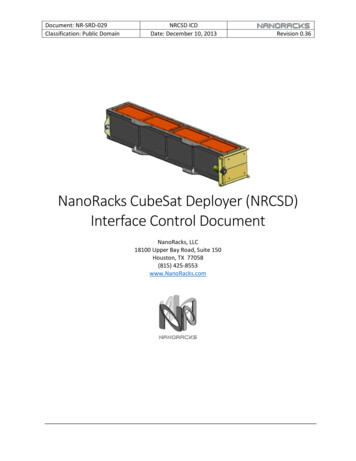
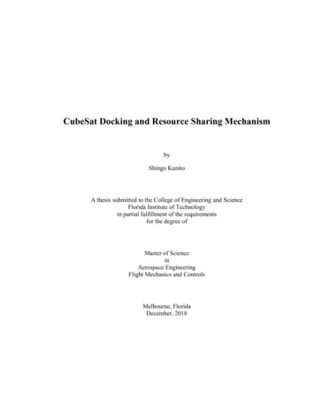
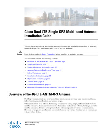
View metadata, citation and similar papers at core.ac.ukEuCAP 2018 1570406531brought to you byCOREprovided by Infoscience - École polytechnique fédérale de 1525354555657606162636465Wideband Cavity-Backed CubeSat Antenna in S bandMiroslav J. Veljovic, Anja K. SkrivervikMicrowaves and Antennas Group (MAG), EPFL, Lausanne, Switzerland, miroslav.veljovic@epfl.chand Earth Exploration‐Satellite services (EES) in the S band,as allocated by the European Cooperation for SpaceStandardization (ECSS). The initial aperture-coupled patchdesign, selected to acquire a better understanding of theantenna operation, is presented in Section II, including themeasurement results of the first prototype. Section IIIdescribes a detailed set of modifications performed on theinitial model, making it suitable for CubeSat applications. Aprototype of the new cavity-backed stacked-patch antennawas built and validated. The measurement results are alsopresented in Section III. Potential limitations of thisgeometry and instructions for handling such limitations aredescribed in Section IV.Abstract—The Telemetry, Tracking and Command(TT&C) antennas are a crucial component of small satellites,as their in-orbit attitude is not always well-defined. The TT&Cantenna design for a CubeSat is an even more challenging task,considering the volume restrictions imposed by the standard,and the bandwidth requirements for a duplex communication.A detailed design process of a low profile S-band antenna,suitable for CubeSat applications, is presented in this paper.The fabricated prototype exhibits a 10-dB impedancebandwidth of 40 %, and a 3-dB axial-ratio bandwidth of 32 %.Index Terms—Cavity-backed, wideband, stacked patchantenna, CubeSat, TT&C.I.INTRODUCTIONCubeSat is the most popular standard for small modularsatellites. Each CubeSat is comprised of Units (U) - cubeshaving a size of 100 x 100 x 100 mm3 and a mass of up to1.33 kg [1], with the most popular being 1U, 3U and 6Usatellites [2]. The standard attracts many universities andindustries with its low cost of building and orbitaldeployment. The small available volume and weight posestrict constraints on the system design, including the onboard antennas. During the launch, no feature on the satellitesurface should protrude the volume designated by thestandard, and either low-profile or deployable antennastructures are used [3].Several antennas on board CubeSats realize variousfunctions and their frequencies vary from VHF to Kabands [3]. Among others, Telemetry, Tracking andCommand (TT&C) are vital for each satellite mission. Rightafter a satellite is detached from the launch vehicle, theattitude is not defined and wide-coverage antennas arerequired to establish a link with the ground stations andallow for subsequent satellite operations [4]. Therefore, theTT&C antenna reliability is crucial for a satellite missionsuccess. In this sense, low-profile antennas are a favourablecandidate over fail-prone deployable structures. On the otherhand, size restrictions, primarily on the antenna thickness,result in limitations on the achievable impedance and axialratio (AR) bandwidth with this kind of antennas, especiallyin the lower frequency bands. This is a known issue withplanar antennas, and so far, only a few CubeSat antennadesigns that yield narrowband AR performance are proposedfor S-band frequencies [5], [6].In this paper, we present a design of a wideband lowprofile circularly-polarized (CP) cavity-backed patch antennathat fits on a single side of a 1U CubeSat and covers theIndustrial, Scientific and Medical (ISM) 2.4 GHz band andfrequencies for Space Operation (SO), Space Research (SR)II.APERTURE-COUPLED PATCH ANTENNAThe initial antenna requirements are summarized inTable 1.An aperture-coupled patch antenna [7] was selected for apreliminary model, since this geometry provides the mostbandwidth, compared with other methods of exciting patchantennas (coaxial pin, microstrip line). To better understandthe operation of this antenna, a linearly-polarized (LP)microstrip-fed element was first tuned for the desiredfrequency band, having a minimal antenna thickness for thespecified bandwidth. The circular polarization is thenachieved using a crossed slot and a feeding network based onT-junction power dividers, quarter-wavelength transformersand phase-delay lines. The design was carefully analysed inseveral steps, gradually increasing the feeding networkcomplexity. Antenna geometry with intermediate designsteps is shown in Fig 1.The design was verified through a prototype shown inFig. 2(a). RT Duroid 5870 substrate (εr 2.33, tanδ 0.0012,h 0.508 mm) is used for the feeding network and thecoupling slot, the patch is etched on a thin FR4 sheet(εr 4.55, tanδ 0.02, h 0.2 mm) and separated from the slotusing a space-eligible hard foam material (εr 1.08,tanδ 0.0002, h 10 mm). Individual layers are attachedtogether using nylon screws.TABLE I.Frequency band [GHz]Antenna gain [dBi]Beamwidth [ ]S11 [dB]Axial Ratio [dB]Dimensions [mm3]1INITIAL ANTENNA REQUIREMENTS2 – 2.45 ( 20%) 5 50 -10 3100 x 100 x 12
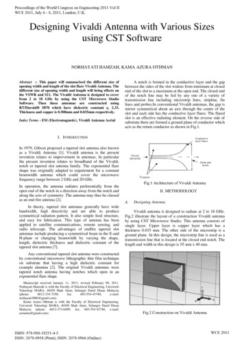
The issue could be overcome if a better matching isachieved for a single element, which would reduce thereflections inside the network, or if Wilkinson dividers wereused instead of T-junctions, in which case the reflectionswould be dissipated in the dividers’ resistors. However, inthis case, the active reflection coefficient of the antenna islimited by the available thickness, and T-junctions wereselected as they allow a simpler manufacturing process.a)b)c)d)a)e)Fig. 1. Aperture-coupled patch antenna model evolution. a) LP model1. b) LP model 2. c) CP 4-port model. d) CP full model. e) Crosssection view. The figures show the feeding lines (black), the patch(dark grey) and the slots (light grey).The prototype is characterized in an anechoic chamber, andthe measured results are compared with the simulations inFig. 2(b).An intermediate 4-port model, that excludes the feedingnetwork, is used to correctly evaluate the coupling to theradiating patch. The response of the 4-port model, shown inFig. 2(b), is a good indicator of the power accepted by thepatch in the desired polarization. The port excitation mimicsthe feeding network performance, and the active Sparameters (1) are calculated in order to evaluate the reflectioncoefficient of the antenna in this configuration.T-junctions are used in the full model as power dividers,thus multiple reflections exist inside the feeding network.The reflected signals ultimately arrive at the coupling slotswith an unwanted phase shift and effectively contribute tothe cross-polarization. This explains the low values of S11 forthe full model, shown in Fig. 2(b). Moreover, the similaritybetween the active-S1 of the 4-port model, and the AR of thefull model seen in Fig. 2(c), confirms the previous analysis.b)1The active S-parameters of an N-port network are obtained usingthe following expression:Nactive - Sm S mnn 1an, m 1,., N ,amwhere Smn are the conventional S-parameters. Parameter active-Smgives the reflected power in port m when all the ports are excited in aspecified way (compared to the conventional S-parameters, whereports are excited one at a time).c)Fig. 2. Aperture-coupled patch antenna. a) A realized prototype. b)The reflection coefficient. c) Simulated gain and axial ratio.2
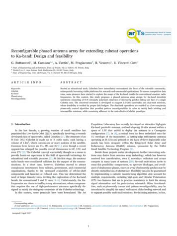
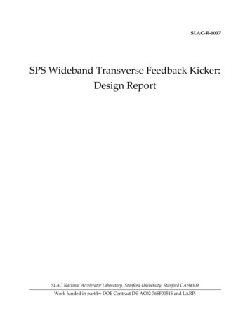
III.CAVITY-BACKED PATCH ANTENNAA metallized FR4 is used as the second ground plane. Thepatches are etched on two other FR4 sheets (h 0.1 mm) andseparated using two hard foam layers (h 4 mm, h 5 mm).All the layers are attached with nylon screws. Theconductive shield around the stripline was first approximatedwith a pin wall, having the pin separation of 15.6 mm( 0.1 λg, where λg is the wavelength inside the stripline at 2GHz). The pins were manually soldered to the two groundplanes, since metallized vias, or any kind of metallization atall, is not feasible on the foam material. The firstmeasurements were performed in this configuration.Afterwards, the stripline was enclosed with a conductivetape, and the measurements were repeated.Once the antenna is mounted on the CubeSat, it isnecessary to isolate it from the interior satellite components,in order to ensure a proper operation of both the antenna andon-board electronics. This can be accomplished by using astripline-based feeding network. In this case, the electricfield strength is equally distributed between the two groundplanes in the substrate, which results in a poor coupling tothe radiating patch. It is shown that the coupling to the patchis the critical point of this design, considering the bandwidthrequirements and the thickness limitation. Severalmodifications were performed to improve it: A second, smaller patch was added below the originalone, to improve the coupling at the higherfrequencies. By adding the second patch, the totalantenna thickness remains unchanged. Instead of a stripline, a layer of low-permittivity foamand a second ground plane were added above themicrostrip lines. The resulting structure can beconsidered as an asymmetric stripline [8] and itfocuses the electric fields in the dielectric layer closeto the slot, ensuring a stronger coupling. Thisapproach alone is, however, ineffective for a smallground plane separation that is required here, as theproximity of the second ground plane deteriorates theperformance. This effect is demonstrated in Fig. 3. Mode-suppression pins were placed around the slot toreduce the power transferred to the parallel-platemode in the stripline. The introduction of pins had anoverall negative effect on the coupling since itperturbed the electric field distribution inside thestripline, in the vicinity of the slot. This effect wasobserved regardless of the number of pins, even if thedensity as high as λg/10 is used [9]. Following the conclusions drawn from the previouspoint, the key modification was to enclose the wholefeeding structure from all sides with a conductivelayer, effectively creating a rectangular cavity in theasymmetric stripline. The electric field distributioninside the cavity has a maximum at the position of theslot, which drastically increases the power deliveredto the radiating patch, and improves the overallantenna performance.Fig. 3. Active S-parameter of the 4-port asymmetric-stripline model,for different separations of the second ground plane (h).Other modifications are also possible, such as changing theshape of the slots, but they were not considered in this work.A modified feeding network, based on Wilkinson powerdividers and phase-delay lines, is used for the full antennamodel, shown in Fig. 4. The result is a substantialimprovement of the AR values, in comparison with the Tjunction-based feeding network, as the reflected signals arenow absorbed by the dividers’ resistors.A prototype of the cavity-backed antenna was built toverify the design. The feeding asymmetric stripline consistsof an RT Duroid 5870 substrate (εr 2.33, tanδ 0.0012,h 0.508 mm) and a low-permittivity hard foam material(εr 1.08, tanδ 0.0002, h 2 mm).a)b)Fig. 4. A cavity-backed stacked-patch antenna model. a) The topview, including the feeding network (black), the patch elements (darkgrey) and the slot (light grey). b) Cross section view.3
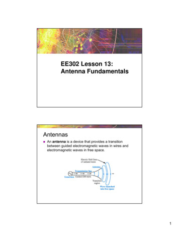
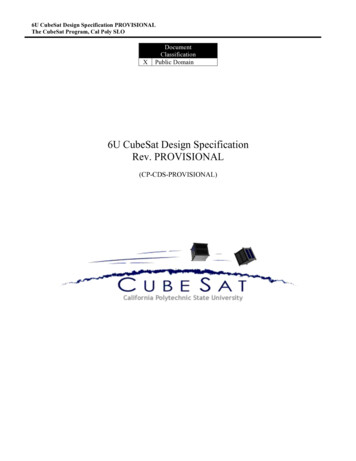
The results are shown in Fig. 5. The measured S11 isbetter than -17 dB along the whole required frequency band,and the measured gain and axial ratio are better than 7.4 dBiand 1.6 dB, respectively. The measured antenna beamwidthis between 62 and 72 . The overall measured 10-dBimpedance bandwidth is 40 % and the measured AR issmaller than 3 dB over a bandwidth of 32 %.The total size of the antenna is 100 x 100 x 12 mm3(0.67 λ0 x 0.67 λ0 x 0.08 λ0, where λ0 is a free-spacewavelength at 2 GHz). The total weight of the antenna is49 g.IV.a)ELECTRIC FIELD DISTRIBUTION INSIDE THE CAVITYThe metallic cavity enclosing the feeding substrates isresonant at certain frequencies and it is necessary to ensurethat the resonant modes do not appear inside the operatingbandwidth of the antenna. For a feeding substrate dimensionof 100 x 100 x 2.5 mm3, which corresponds to a 1U CubeSatface, the first two resonant modes appear at 1.93 and3.05 GHz, and do not compromise the antenna performance.To better understand the effect of the pin placement andsubstrate shielding on the reflection coefficient, the electricfield distribution inside the cavity is examined. A 4-portantenna model was used in the simulations in the samemanner as previously described, and active S-parameterswere calculated. Some characteristic examples of the fielddistribution inside the cavity, and the corresponding active Sparameters, are shown in Fig. 6 for illustration.It is seen that a low intensity of the electric field in thecentre of the cavity (close to the slot) results in a poorcoupling to the patch, and vice versa. In the last case, seen inFig. 6(c), where four shorting pins were placed in addition tothe shield, the resonant frequency of the structure hasincreased and appears within the operating range. Here, theplotted field distribution is calculated at the resonantfrequency and the field strength is an order of magnitudehigher than at the other frequencies.The cavity modes are evident in the measured S11 curves,shown in Fig. 5(c). The model with the pin wall has a lowerresonant frequency (1.84 GHz) since the electric field isfringing between the pins, increasing the effective size of thecavity. Similarly, the effective cavity size of the model withthe pins and the conductive tape is smaller, resulting in ahigher resonance (1.94 GHz). These resonances are notalways visible in the simulation results due to the selection ofthe interpolating frequency-sweep technique used in the EMsoftware.A good practice would be to allow for a safety marginbetween the cavity mode and the lowest operating frequencyof the antenna. To ensure this, it is important to use thewhole available surface in the interior of the satellite for thefeeding structure, as this will yield a lower resonantfrequency. If the antenna is to be mounted on a 3U CubeSatand placed on a long face, the cavity can be further enlarged.Otherwise, a higher-permittivity dielectric can be used forthe feeding substrate, which would eventually produce asimilar effect.b)c)d)Fig. 5. A cavity-backed stacked-patch antenna. a) The individuallayers of the prototype. b) The realized prototype with a conductivetape around the feeding asymmetric stripline. c) The reflectioncoefficient. d) The antenna gain and axial ratio.4
The next steps are the antenna placement and integrationon the CubeSat, and the analysis of the antenna in a CubeSatenvironment.ACKNOWLEDGEMENTa) f 2.225 GHz, Emax 5 kV/mThe work presented in this contribution was funded bythe Swiss Commission for Innovation and Technology, inproject 18328.1 CubeSatCom. In the frame of this project,we would like to acknowledge our fruitful discussion withFederico Belloni on antenna requirements.b) f 2.225 GHz, Emax 8 kV/mREFERENCES[1][2][3]c) f 2.3 GHz, Emax 60 kV/md)Fig. 6. a) - c) Electric field distribution inside the feeding cavity ofthe stacked-patch antenna (4-port model) and d) the correspondingactive S-parameters. The white colour represents a higher electricfield strength. The red color denotes the locations where the twoground planes are electrically connected.V.[4][5]CONCLUSIONS[6]A step-by-step design process of a low-profile widebandantenna for CubeSat applications is presented. A preliminarymicrostrip-fed aperture-coupled patch antenna was modelledand verified through a prototype. The drawbacks of thisdesign were addressed and improved through a set ofmodifications, making the antenna suitable for small satelliteapplications. The final design is a stacked-patch antenna,backed by an asymmetric-stripline cavity. A fabricatedprototype exhibits a gain higher than 7.4 dBi throughout thespecified bandwidth, a 10-dB impedance bandwidth of 40 %,and a 3-dB AR-bandwidth of 32 %, satisfying all of thedesign criteria.[7][8][9]5CubeSat Design Specification Rev. 13, The CubeSat Program, CalPoly SLO.Kulu, E, Nanosatellite & CubeSat database. Internet :http://www.nanosats.eu/index.html#figures [Oct. 2017].Constantine Kakoyiannis and Philip Constantinou (2011). ElectricallySmall Microstrip Antennas Targeting Miniaturized Satellites: theCubeSat Paradigm, in Microstrip Antennas, Prof. NasimuddinNasimuddin, InTech, DOI: 10.5772/14947, pp. digmGao, S., et al., “Antennas for small satellites”, Proceedings of the2008 Loughborough Antennas and Propagation Conference,Loughborough, UK, Mar. 2008, pp. 66–69.Nascetti, A., Pittella, E., Teofilatto, P., Pisa, S., “High-Gain S-bandPatch Antenna System for Earth-Observation CubeSat Satellites”,IEEE Antennas and Wireless Propagation Letters, Vol. 14, pp. 434437, 2015.Bellion, A., Elis, K., De Gaetano, S., “New compact S-band antennafor Nanosatellite TeleMetry and TeleCommand applications - EyeSatprogram”, European Conference on Antennas and Propagation(EuCAP 2016), Apr. 10-15, Davos, 2016.Ansbro A.P., Crozzoli M., Gianola P., “Design of Circular PolarizedPrinted Antennas in L band”, 10th International Conference onAntennas and Propagation, pp. 314-317, Apr. 1997.Zürcher, J.-F., Gardiol, F.E., Broadband Patch Antennas, ArtechHouse, 1995, pp.55.Brachat, P., Baracco, J. M., “ Dual-Polarization Slot-Coupled PrintedAntennas Fed by Stripline”, IEEE Transactions on Antennas andPropagation, Vol. 43, No. 7, pp.738-742, July 1995.
antenna, CubeSat, TT&C. I. INTRODUCTION CubeSat is the most popular standard for small modular satellites. Each CubeSat is comprised of Units (U) - cubes having a size of 100 x 100 x 100 mm3 and a mass of up to 1.33 kg [1], with the most popular being 1U, 3U and 6U satellites [2]. The standard attracts many universities and