Transcription
CubeSat Docking and Resource Sharing MechanismbyShingo KunitoA thesis submitted to the College of Engineering and ScienceFlorida Institute of Technologyin partial fulfillment of the requirementsfor the degree ofMaster of ScienceinAerospace EngineeringFlight Mechanics and ControlsMelbourne, FloridaDecember, 2018
We the undersigned committee hereby approve the attached thesis, “CubeSatDocking and Resource Sharing Mechanism,” by Shingo Kunito.Markus Wilde, Ph. D.Assistant ProfessorAerospace, Physics and Space SciencesTiauw Hiong Go, Sc.D.Associate ProfessorAerospace, Physics and Space SciencesHamid Hefazi, Ph. D.ProfessorMechanical and Civil EngineeringDaniel Batcheldor, Ph. D.Professor, Department HeadAerospace, Physics and Space Sciences
AbstractTitle: CubeSat Docking and Resource Sharing MechanismAuthor: Shingo KunitoAdvisor: Markus Wilde, Ph. D.This thesis addresses the design concept of a CubeSat docking and resource sharingmechanism that allows to transfer propellant that is pressurized gas, data, and power. Indocking and capture design, the interface is equipped with two air cylinders that are rated upto 20.68 MPa internal pressure generating the ideal force of 1218.4 N each. With thedesigned air cylinder and mounted configuration, the maximum capture distance betweenthe target and the chaser CubeSat is 40.30 mm. Since air cylinder and body frame aredesigned specifically for this interface, structural analysis was conducted in ANSYS whereresults show a minimum factor of safety of 1.38 on air cylinder rod. For propellant transfer,this interface is designed to transfer compresses gas at a maximum pressure of 20.68 MPa.In order to seal this high-pressure gas, force generated by the air cylinder is used to seal thestatic face sealing with a concept adapted from an O-ring seal. For data and power transfer,it uses spring loaded pins which requires only a small amount of force to keep themconnected and almost no force to disconnect. This interface is also equipped with a cameraand a docking target for autonomous rendezvous and docking. The docking target isspecifically designed for this interface adopting the concept from existing docking targets,such as the International Space Station center docking target. Docking target simulation wasalso conducted to see the accuracy of determining the target orientation using imageprocessing in MATLAB.iii
Table of ContentsTable of Contents . ivList of Figures .vList of Tables. viChapter 1 Introduction .11.1 Rendezvous and Docking in Space . 11.2 CubeSat . 21.3 Motivation . 31.4 Objectives . 41.5 Thesis Outline . 4Chapter 2 State of the Art .62.1 CubeSat Docking Interface . 62.1.1 Novel Permanent-Magnet Docking Mechanism . 62.1.2 SPHERES . 72.1.3 Docking Interface Mechanism using Shape Memory Alloy . 8Chapter 3 System Design .103.1 Docking Interface . 103.1.1 Air Cylinder Design . 103.1.2 Docking Alignment Feature . 133.2 Propellant Transfer Interface . 163.2.1 Sealing Design . 183.3 Data and Power Transfer Interface . 203.4 Docking Target and Camera. 223.4.1 Docking Target Design . 233.4.2 Camera Selection . 253.5 Final System Architecture . 26Chapter 4 Analysis and Simulations .314.1 Structural Analysis and Simulation . 314.2 Docking Target Analysis and Simulation. 334.2.1 Image Processing Simulations . 37Chapter 5 Conclusion .485.1 Recommendations for Future work . 49Reference.50iv
List of FiguresFigure 1: Model of Kosmos-186 and Kosmos-188 [1] .1Figure 2: 1U CubeSat [3] .2Figure 3: Nanosatellite Launches [4] .3Figure 4: 3U CubeSat Novel Permanent-Magnet Docking Interface [5] .6Figure 5: Docking Port SPHERES [6] .7Figure 6: Docking Interface using Shape Memory Alloy[7] .8Figure 7: Cylindrical Vessel [8] .11Figure 8: Air Cylinder Specifications .12Figure 9: Air Cylinder Alignment .13Figure 10: Detailed Dimensions for Mechanical Alignment .14Figure 11: First Mechanical Alignment Feature .14Figure 12: Second Mechanical Alignment Feature .15Figure 13: Axial Seal and Radial Seal [9].16Figure 14: Section Cut View of the Groove and the Sealing Material .19Figure 15: Male and Female Electrical Connector .21Figure 16: Center Docking Target of ISS [11].22Figure 17: Target Orientation [12] .23Figure 18: Designed Docking Target .24Figure 19: ELP 5mp 60 Degree Autofocus USB Camera [13] .25Figure 20: CubeSat Docking Interface .27Figure 21: First Docking Phase .27Figure 22: Second Docking Phase .28Figure 23: Third Docking Phase .29Figure 24: Fourth Docking Phase .30Figure 25: Pressure Analysis of Cylinder Vessel using ANSYS .31Figure 26: Load Analysis of Cylinder using ANSYS .32Figure 27: Static Structural Analysis of Body Frame using ANSYS .33Figure 28: Coordinate System and Docking Target .35Figure 29: Camera Image Coordinate System .36Figure 30: No Yaw, Pitch and Roll Angles .38Figure 31: 10 of Roll with no Yaw and Pitch Angles .40Figure 32: -10 of yaw, with no pitch and roll .41Figure 33: 10 of pitch, with no yaw and roll .43Figure 34: -10 of yaw and 10 of pitch with no roll .44Figure 35: 10 of pitch and roll with -10 of yaw .46v
List of TablesTable 1: Pin Configuration for Micro-A USB [10].20Table 2: ELP 5mp 60 Degree Autofocus USB Camera Specification [13] .26Table 3: Parameters Used for Image Processing.34Table 4: Results on No Yaw, Pitch and Roll Angles .39Table 5: Results on 10 of Roll with no Yaw and Pitch Angles .41Table 6: Results on -10 of Yaw, with no Pitch and Roll .42Table 7: Results on 10 of Pitch, with no Yaw and Roll .44Table 8: Results on -10 of yaw and 10 of pitch with no roll .45Table 9: Results on 10 of pitch and roll with -10 of yaw .46vi
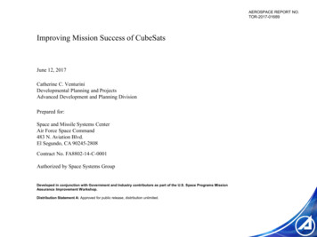
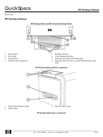
1Chapter 1Introduction1.1 Rendezvous and Docking in SpaceRendezvous and docking is one of the important technologies in space missions and it hasbeen studied, analyzed, experimented and being used in the missions over the past 50 years.The idea of rendezvous and docking technology was developed due to the limitation of sizeand mass that can be launched into space per launch. With rendezvous and dockingtechnology, it allowed space missions to have bigger scale and longer time period of missioncompare to the old ages.In 1966, first docking in space was conducted by two spacecraft, Gemini VI and VII withpiloted rendezvous. For automatic docking in space was demonstrated on October 30, 1967by the Soviet Union with their two spacecraft, Kosmos 186 and 188 [1].Figure 1: Model of Kosmos-186 and Kosmos-188 [1]
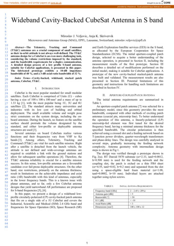
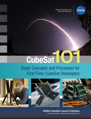
2Upon rendezvous with the target, there are two possible approaches for target or chaser todock with each other. The first docking method is by docking directly to the docking port.This method requires precise rendezvous, approach maneuvers, and alignment between twospacecraft. It is also described as a controlled collision and with this, capture and connectionhappen at the same time. The second docking method is berthing, where the chaser spacecraftperforms rendezvous and approaches close to the target spacecraft. Then a robotic arm oneither target or chaser spacecraft is used to grab the other spacecraft and to bring it into thedocking interface. One of the berthing examples is International Space Station, which usesits robotic arm to capture resupply modules. The advantage of berthing is that it does notrequire precise alignment with the target.1.2 CubeSatCubeSats have become very common testing instruments in space for researchers,commonly in Low Earth Orbit space research applications. The first CubeSat was developedin a collaborative effort between California Polytechnic State University and StanfordUniversity's Space Systems Development Laboratory [2]. Generally, a CubeSat is classifiedas a Nanosatellite with its net mass being between 1 and 10 kg. CubeSat has its own standarddimension defined as 1U, which is 10x10x10cm that can be increased such as 1.5U, 2U, 3U,and 6U.Figure 2: 1U CubeSat [3]
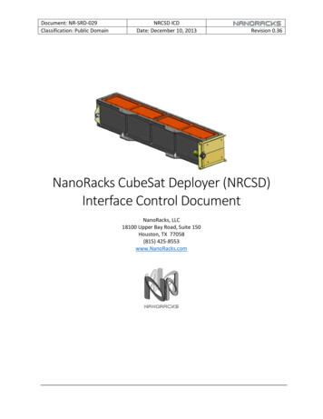
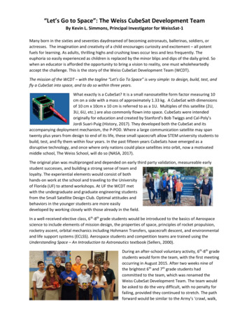
3According to the Nanosatellite database, during the year of 2016, 88 Nanosatellites werelaunched into space whereas during the year of 2017, 294 Nanosatellites were launched intospace. Form this fact, it is possible to predict there will be an increase in number ofNanosatellites launches in the future [4].Figure 3: Nanosatellite Launches [4]As shown in Figure 3, CubeSats are becoming very common research instruments to test inspace, there are many attachments that could be equipped on CubeSats. Commonattachments include reaction wheels, magnetic torquers, cold gas thrusters, dockinginterfaces etc.1.3 MotivationCubeSats are very flexible in size and of relatively low cost compared to other spacecraft,but are still limited on what they can do. There are several docking mechanisms developed
4for CubeSats, but there has not been much development on implementing bidirectionaltransfer between two CubeSats for pressurized propellant gas.Building the CubeSat interface mechanism which is capable of docking and sharingresources will enhance the capability of CubeSats that can be used for different approachand be in larger scale researches. For example, it will allow us to assemble larger spacecraftfrom CubeSat size satellites. This interface can also be used as the testing platform forrendezvous and docking controllers.1.4 ObjectivesThis paper demonstrates the design concept of a docking interface mechanism that will allowCubeSats to dock and share resources. This interface includes mechanical docking,pressurized propellant gas transfer at a maximum pressure of 20.68 MPa, electrical data andpower transfer, and a docking target for autonomous rendezvous and docking. Thesemechanisms are built in a single interface within 1U that is attachable to any CubeSats. Inaddition to that, if the target CubeSat is equipped with this docking interface, any CubeSatswill be able to dock each other.1.5 Thesis OutlineThis thesis focuses on the design and analysis of CubeSat docking interface mechanism thatallows to share their resources such as propellant, electrical data and power while docking.The first chapter presents the motivation and objectives of the thesis. The second chapterpresents different CubeSat interface designs that were developed in the past. The thirdchapter presents the system design for docking mechanism, propellant transfer mechanism,electrical data and power transfer mechanism, and docking target design for autonomousdocking. The fourth chapter presents the structural simulations using ANSYS to satisfy thestress requirements and image processing of the docking target analyzed using MATLAB.
5The final chapter presents the conclusion and analysis of CubeSat docking interfacemechanism and recommendations for future work.
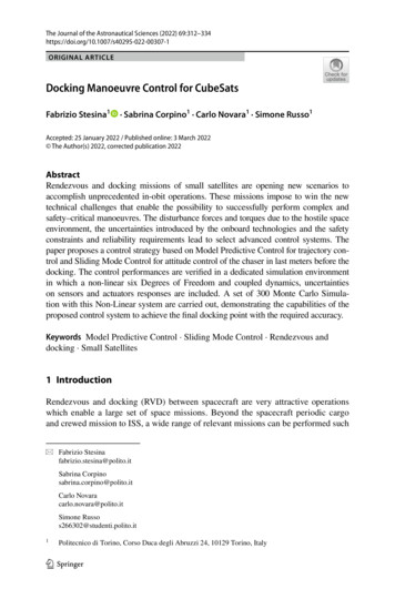
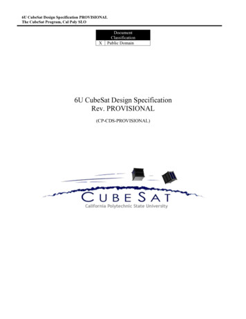
6Chapter 2State of the ArtCubeSats have been in use since 1999, whereas rendezvous and docking was demonstratedin 1966 by Gemini VI and VII. Technology development for data, power, and propellanttransfer mechanism are already being applied and used on International Space Station.Although these individual technologies have already been developed and are available, therehas not been much development on CubeSat docking systems that allow CubeSats to sharetheir resources.2.1 CubeSat Docking Interface2.1.1 Novel Permanent-Magnet Docking MechanismFigure 4: 3U CubeSat Novel Permanent-Magnet Docking Interface [5]This docking interface is a collaborative work between NASA Langley Research Center andCornell University to demonstrate rendezvous and docking of two 3U CubeSats using novelpermanent-magnet for docking. This novel permanent-magnet system eliminates the need
7for precise sensors or actuators requirements for docking and simplifies the overall dockingmechanisms. This technology was tested on ground at NASA Langley Research Center ona 3 by 4 meters granite table and two nearly frictionless air bearing systems that support thetwo CubeSats. From their extensive test results, it was demonstrated that the proposedmagnetic docking concept eliminates the need for high precision sensors and actuators fordocking [5]. This docking concept is very unique and reduces mechanical complexity as wellas instruments cost such as high precision sensors or actuators, but does not includepropellant transfer. Also, this docking concept is not realistically possible to transfer highpressure gas due to the limitation on magnetic force. Overall concept presented in this novelpermanent-magnet docking mechanism is much more based on autonomous dockingdemonstration rather than a resource sharing mechanism for CubeSat.2.1.2 SPHERESFigure 5: Docking Port SPHERES [6]
8SPHERES (Synchronized Position Hold, Engage, Reorient Experimental Satellites) is atestbed operated by MIT and NASA Ames on the ISS. The purpose of this testbed is to studythe phenomena of docking in space, and the characteristic of their behavior when twospacecrafts are docked. As shown in Figure 5, each Docking Port has a metal lance and anopening beside one another. As the metal lance fully enters the other Docking Port’s opening,a photosensor inside the port senses and activates a motor, which closes two metal camsaround the lance. this Docking Port has camera that allows a human controller to guide thesatellite and also provides input for autonomous docking maneuvers [6].2.1.3 Docking Interface Mechanism using Shape Memory AlloyFigure 6: Docking Interface using Shape Memory Alloy[7]This spacecraft docking interface mechanism is was patented by Marcello Romano and PaulOppenheimer at the Naval Postgraduate School. This docking interface is capable ofdocking, data and power transfer and fluid transfer up to 20.68 MPa pressure. A uniquecharacteristic of this method is its use of shape memory alloy to keep them docked. Shapememory alloy is used at the tip of number 18 in Figure 6, is the place for high pressure fluidtransfer between two spacecraft [7]. This interface is also equipped with electromagnets
9located at 44 and 46 to provide active assistance in close proximity operation alignment butdoes not contain any autonomous docking feature such as docking target or camera. ThisCubeSat interface provides all the features of a resource sharing mechanism, but using shapememory alloy in the design is very complex and relatively expensive to manufacture. Also,this docking interface using shape memory alloy is registered as patent [7].Overall, there are several docking interfaces developed for CubeSats in the past, but thecurrent focus on CubeSat technology development seems to be one step behindexperimenting and development on autonomous docking control systems.
10Chapter 3System Design3.1 Docking InterfaceDocking in space requires some kind of force or mechanisms to keep target and chaserspacecraft connected depending on their purpose for docking. The key mechanism of thisdocking interface is its use of an air cylinder to capture and retract the target for docking.This air cylinder receives pressurized air from the propellant tank equipped on the CubeSatthat is used for thrusters. This interface assumes that the propellant used for thruster is acompressed gas of about 20.68 MPa in pressure. Since this pressurized propellant is availableon board, the pressure is utilized to create enough retraction force by cylinder for captureand docking.The purpose of this docking interface is to share resources bi-directionally, includingpropellant gas, data, and battery power. Among these three resources, propellant transfer isthe dominant force working against the docking force trying to separate between twospacecraft. Therefore, the docking force needs to be greater than the minimum sealing forceneeded for propellant transfer.3.1.1 Air Cylinder DesignThere are several types of air cylinder, whether it is spring return, spring extend, singleacting, double acting etc. Docking requires motion that will hook onto the target’s body andpulls it towards the chaser as the cylinder rod retracts. Therefore, a spring extend singleacting air cylinder is selected so that when there is no pressure inside, the cylinder rod isfully extended by the spring. To determine the sizing of the air cylinder, wall thickness forthe cylinder is calculated based on the pressure vessel requirement.
11Figure 7: Cylindrical Vessel [8]Consider a cylindrical pressure vessel shown in Figure 7 with a radial wall thickness t andinner radius r. To analyze whether the selected material and thickness could withstand theinternal pressure P, hoop stress 𝜎1 and longitudinal stress 𝜎2 are calculated using thefollowing equations [8]𝜎1 𝑃 𝑟𝑡(1)𝜎2 𝑃 𝑟2𝑡(2)By comparing Equation (1) and Equation (2), the hoop stress 𝜎1 is double of 𝜎2 , whichmeans that with a given cylinder, hoop stress is the dominant stress for stress analysis.Therefore, Equation (1) is used to determine the wall thickness of the cylinder. By solvingfor 𝑡 in Equation (1), the thickness can be represented as a function of pressure, radius andhoop stress as it is shown in the equation below.𝑡 𝑃 𝑟𝜎1(3)
12It is known that the maximum possible pressure 𝑃𝑚𝑎𝑥 in the cylinder is 20.68 MPa, theinternal radius is selected to be 5 mm, so that the pressure applied on cylinder rod’s boreproduces enough cylinder retraction force. Material for this cylindrical vessel is SteelASTM-A913 Grade 450 which has yield strength of 450 MPa, ultimate strength of 550 MPain tension and 7860 kg/m3 density [8]. Using these values in Equation (3) gives the wallthickness 0.23 mm. For safety, wall thickness for this cylinder is designed to be 2 mm.Overall cylinder dimensions are shown in Figure 8.Figure 8: Air Cylinder SpecificationsAs shown in Figure 8, the cylinder is equipped with a spring inside at the base to extend outthe rod so that when there is no internal pressure, the rod is fully extended. The effectivesurface area for piston motion is 58.9 mm2 which is simply calculated by subtracting therod cross section area from the bore cross section area. The maximum ideal force generatedby a single cylinder is 1218.4 N.One of the characteristics of a cylinder is that it can only move along one axis. This resultsin more complexity in designing the method for the cylinder rod be hooked onto the targetCubeSat. To overcome this problem, the air cylinder is mounted at an angle so that strokemotion will now provide two degrees of freedom.
13Figure 9: Air Cylinder AlignmentTo ensure stable docking, two identical cylinders is mounted with 15 tilt from the dockingsurface for each cylinder as it is shown in Figure 9. With this design, cylinder stroke motionis able to direct outwards from center of the body. Stroke of the cylinder is 65 mm so thatwith this tilt alignment, cylinder is able to move 62.79 mm perpendicular to the interfacesurface and 16.82 mm parallel to the interface surface directing outwards. Maximumdistance between chaser and target for capture is 40.30 mm.3.1.2 Docking Alignment FeatureWhen two spacecraft are docking, manually or autonomous, it is not possible to dockprecisely without any misalignment. This is the reason why there are alignment features built
14into the interface. The first mechanical alignment becomes relevant during capture and asboth chaser and target CubeSats get closer, as shown in Figure 11. The second mechanicalalignment provides the final correction for final docking shown in Figure 12. For bothmechanical alignment features, the detailed dimensions are shown in Figure 10.Figure 10: Detailed Dimensions for Mechanical AlignmentFigure 11: First Mechanical Alignment Feature
15The first mechanical alignment feature becomes relevant during the capture process. It islocated on the side of the interface body that is also used for capture. This alignment feature’sallowable offset decides the baselines for image processing alignment accuracy that uses thedocking target. From the design shown in Figure 10, maximum allowable offset based onwidth dimension is 8 mm. This alignment design has sloped surface so that if it is withinthe range of 8 mm, the cylinder rod will automatically slide into the desired hook in portas it gets retracted.Figure 12: Second Mechanical Alignment FeatureThe second mechanical alignment feature is at center of the interface. This is used for thefinal alignment for docking when the first mechanical alignment was still off from desiredposition. This becomes relevant when the distance between target and chaser CubeSats is15 mm.
163.2 Propellant Transfer InterfaceThe goal for the propellant transfer interface is to transfer high pressure cold gas with amaximum pressure of 20.68 MPa, which is one of the main capabilities of this dockinginterface. For comparison, the recommended pressure rating for a typical car tire is about206.8 kPa, so the pressure transferred through the interface is about 100 times higher thanthose in typical car tires. In order to transfer this high-pressure gas between two CubeSatswhile docking, a mechanical connection that can withstand the pressure is required. Thereare different types of mechanical pipe connections, but this high-pressure gas transferinterface focuses on creating a sealed interface by using the elastic material sealing method.One of the most common sealing methods in machine design is O-ring seal. This type ofsealing is very common because O-rings are cheap and easy to manufacture, simple to equip,and very reliable. There are two main types of seals, static seals and dynamic seals. Thereare two different categories in static seals, axial sealing and radial sealing, which is definedby the squeeze direction acting on the sealing material.Figure 13: Axial Seal and Radial Seal [9]Figure 13 shows the O-ring sealing configurations for axial and radial seals. The ideal Oring seal design can be determined by the O-ring dimension, its squeeze percentage, groove
17shape and dimension. When designing an O-ring seal, the axial thickness of the O-ringshould generally be compressed to between 10% to 40% of its original height. In addition,the groove volume can be filled up by the sealing material with a range between 70% to 90%after being fully compressed so that it doesn't overfill the groove. Overfilling the groove maycause a sealing failure resulting in leakage. To ensure minimum leakage across the sealing,the pressure experienced on the sealing material must be greater than the pressure that isbeing sealed [9].The air cylinder designed for docking shown in section 3.1.1 is capable of producing1218.4 N at 20.68 MPa internal pressure. Since each interface is mounted with two cylinders,the maximum force that can be used for sealing is 2436.8 N. Docking with this kind of highforce applied between two objects is very similar to static face sealing that is shown in Figure13. Therefore, this force is the primary force for propellant transfer sealing design.The sealing material configuration is one of the important aspects for static axial sealing.Since both target and chaser use the identical docking interface, the sealing shape cannot beO-ring. Therefore, instead of having round cross-sectional shape, rectangular shaped sealingis used on both interfaces. Another difference in this sealing design compared to O-ring isthat sealing material is fixed to the bottom surface of the groove where O-ring is placed onthe groove.Since this kind of design was not done in the past, this sealing is designed based on the Oring sealing and the manual “seal design guide” which is the O-ring seal design manualdocument provided by Apple Rubber [9] is used as a reference for designing high pressuregas transfer sealing. The reason for using manufacturer guidebook is that, there is no accessto the theoretical method in designing the optimum groove sizing with a given O-ringdimensions for public, which is why the manual contains lists of specific groove sizing forspecific O-rings. Another point is that using rectangular material to seal seems to be similarto gasket seal, but the difference between O-ring seal and gasket seal is that most of thegasket sealing uses hard material such as metals and requires high sealing load whereas O-
18ring seal generally uses an elastic material such as rubber. Therefore, sealing design is basedon more towards O-ring sealing.There are several rules of thumb provided in the manual for O-ring sealings which might notapply to the current design, but here are some rules that should be considered in the design[9]. Groove Depth must be less than cross section when creating seal squeeze Maximum volume of sealing material should never be greater than the minimumvolume of groove Cross sections are generally compressed from 10% to 40% for static seal You must test all seals in their actual environment because every application is uniqueThe last point is one of the most important tests which must be conducted in order to validatethe performance and the best way to prove whether the specific design works or not.3.2.1 Seali
University's Space Systems Development Laboratory [2]. Generally, a CubeSat is classified as a Nanosatellite with its net mass being between 1 and 10 kg. CubeSat has its own standard dimension defined as 1U, which is 10x10x10cm that can be increased such as 1.5U, 2U, 3U, and 6U. Figure 2: 1U CubeSat [3]