Transcription
Document: NR-SRD-029Classification: Public DomainNRCSD ICDDate: December 10, 2013Revision 0.36NanoRacks CubeSat Deployer (NRCSD)Interface Control DocumentNanoRacks, LLC18100 Upper Bay Road, Suite 150Houston, TX 77058(815) 425-8553www.NanoRacks.com
Document: NR-SRD-029Classification: Public /12/138/16/13NRCSD ICDDate: December 10, 2013Revision 0.36Approved DetailsInternal document versionInternal document versionJMUpdates to include NanoRacks CubeSatMDJRevised Section 3.14Revised Section 3.59/5/13KDWMDJRevised Section 3.15 to require separation spring.Added specs and figures.9/12/13 KDWMDJRevised Fig 5 battery circuitRemoved section 5.5 additional requirements,Removed section 7 Payload Ground Handling Data12/10/13 KDW, MR MDJMajor Revision NanoRacksAuthorACPACPACPKDWPage 2 of 15
Document: NR-SRD-029Classification: Public DomainNRCSD ICDDate: December 10, 2013Revision 0.36AcronymsCTBkgfNRCSDRBF NanoRacksCrew Transfer Bagkilogram-forceNanoRacks CubeSat DeployerRemove Before FlightPage 3 of 15
Document: NR-SRD-029Classification: Public DomainNRCSD ICDDate: December 10, 2013Revision 0.36Table of Contents1Introduction . 51.1Document Purpose . 51.2Scope . 5234Timeline. 5General Requirements . 5Physical Interfaces . 64.1NanoRacks CubeSat Deployer (NRCSD) Description . 64.2NRCSD Coordinate System . 74.3Access to CubeSat Inhibit Switches and Service Ports . 74.4Mass Properties . 7567894.5CubeSat Dimensional Requirements . 84.6CubeSat Rails . 104.7Deployment Switches . 124.8Separation Springs . 124.9Deployment Compatibility . 13Electrical Interfaces . 135.1Electrical System Design . 135.2Batteries . 14Launch Loads . 15Thermal Interfaces . 15Hazardous Materials . 15CubeSat Integration . 15List of FiguresFigure 1 NRCSD . 6Figure 2 NRCSD Coordinate System . 7Figure 3: Lateral view of NRCSD and access panel dimensions . 7Figure 4 CubeSat Envelope Dimensions. 8Figure 5 NRCSD Axial Cross-Section ( Z view). . 9Figure 6 CubeSat Rail and NRCSD Rails Clearances ( Z view, Y top). 10Figure 7 CubeSat Rail Standoff Clearance . 11Figure 8 Dimensional fit check gauge cross section view . 11Figure 9 Roller/Slider Switch NRCSD Geometry. 12Figure 10 Separation spring placement options . 13Figure 11 Separation spring rail standoff geometry . 13Figure 12 CubeSat Electrical Subsystem Block Diagram (note: RBF switch not shown) . 14 NanoRacksPage 4 of 15
Document: NR-SRD-029Classification: Public DomainNRCSD ICDDate: December 10, 2013Revision 0.361 Introduction1.1 Document PurposeThis Interface Control Document (ICD) defines the interface requirements between the NanoRacksCubeSat Deployer (NRCSD) and CubeSats for developers utilizing NanoRacks CubeSat deploymentservices.1.2 ScopeThe ICD provides the minimum requirements for compatibility with the NRCSD and International SpaceStation (ISS) flight safety program when using NanoRacks CubeSat deployment services. NanoRacksverifies compliance on behalf of CubeSat developers based on incremental data requests.2 TimelineThe following timeline of launch-minus dates are provided as template example when using theNanoRacks CubeSat deployment services. Tailored agreements can be discussed as part of contractnegotiations.Launch-minus datesL – 12 to 14 monthsL – 10 monthsL – 8 monthsL – 4 monthsL – 1 to 3 monthsActivityContract Signing Functional Description Interface Drawings Material Identification and Usage ListFirst data call to CubeSat developer for ISS safety processEnvironmental testingDelivery to NanoRacks3 General Requirements1) CubeSats shall be passive and self-contained from the time they are loaded into the NRCSD fortransport to the ISS and until after deployment from the NRCSD. No charging of batteries,support services, and or support from ISS crew is provided after final integration.2) CubeSats shall not contain pyrotechnics unless the design approach is pre-approved byNanoRacks. Electrically operated melt-wire systems for deployables that are necessary controlsfor hazard potentials are permitted.3) CubeSats must have a timer (set to a minimum of 30 minutes) before satellite operation ordeployment of appendages. If deploy switches should be released causing the timer to run, thetimer must automatically re-set whenever the Remove Before Flight (RBF) feature is replacedand/or the deploy switches are returned to the open state.4) CubeSats should not have detachable parts or create any space debris during launch or normalmission operations.5) CubeSats shall use a secondary locking feature for fasteners external to the CubeSat chassis. Anacceptable secondary locking compound is LocTite. Contact NanoRacks for the proper lockingcompound application procedure. Other secondary locking methods must be approved byNanoRacks. NanoRacksPage 5 of 15
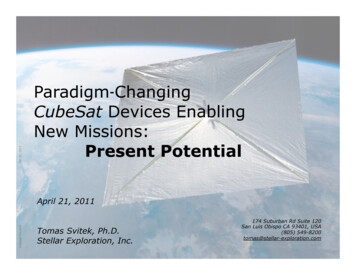
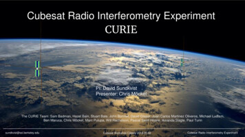
Document: NR-SRD-029Classification: Public DomainNRCSD ICDDate: December 10, 2013Revision 0.366) A description of frangible materials (e.g. solar cells) must be provided to NanoRacks forapproval.4 Physical Interfaces4.1 NanoRacks CubeSat Deployer (NRCSD) DescriptionThe NRCSD is a self-contained CubeSat deployer system that mechanically and electrically isolatesCubeSats from the ISS, cargo resupply vehicles, and ISS crew. The NRCSD design is compliant with NASAISS flight safety requirements and is space qualified.The NRCSD is a rectangular tube that consists of anodized aluminum plates, base plate assembly, accesspanels and deployer doors. The NRCSD deployer doors are located on the forward end, the base plateassembly is located on the aft end, and access panels are provided on the top. The inside walls of theNRCSD are smooth bore design to minimize and/or preclude hang-up or jamming of CubeSatappendages during deployment should these become released prematurely. However, deployablesystems shall be designed such that there is no intentional contact with the inside walls of the NRCSD.Figure 1 NRCSD NanoRacksPage 6 of 15
Document: NR-SRD-029Classification: Public DomainNRCSD ICDDate: December 10, 2013Revision 0.364.2 NRCSD Coordinate SystemThe coordinate system of the NRCSD is a right-handed system shown in Figure 2. The X-axis isorientated as shown in the figure, the Y axis points out of the top of the NRCSD normal to the accesspanels and the Z-axis points forward to the NRCSD the deployer doors.Figure 2 NRCSD Coordinate System4.3 Access to CubeSat Inhibit Switches and Service PortsAccess for RBF pins and charging systems during the integration process is provided through accesspanels located on the topside ( Y axis) of the NRCSD as shown in Figure 3. CubeSats are accessible onlythrough the access panels when integrated with the NRCSD.Figure 3: Lateral view of NRCSD and access panel dimensions4.4 Mass PropertiesMass properties guidelines for CubeSats deployed by NanoRacks are summarized in Table 1. Mass limitsare derived from the maximum ballistic number (BN) allowed for ISS deployed payloads. Exceeding NanoRacksPage 7 of 15
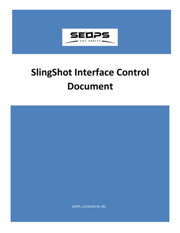
Document: NR-SRD-029Classification: Public DomainNRCSD ICDDate: December 10, 2013Revision 0.36these values requires approval by NanoRacks. The CubeSat center of gravity shall be within 2cm of itsgeometric center.Table 1 CubeSat Mass PropertiesForm Factor Maximum Mass 5 CubeSat Dimensional RequirementsCubeSats nominal envelope maximum dimensions are shown in Figure 5. No external components otherthan CubeSat rails or rail roller/slider switch, if used, shall contact the NRCSD interior. Additionalenvelope provided by a cylindrical recess within the NRCSD pusher plate is available subject to approval.Figure 4 CubeSat Envelope Dimensions NanoRacksPage 8 of 15
Document: NR-SRD-029Classification: Public DomainNRCSD ICDDate: December 10, 2013Revision 0.36The NRCSD interior envelope is shown in Figure 5.Figure 5 NRCSD Axial Cross-Section ( Z view). NanoRacksPage 9 of 15
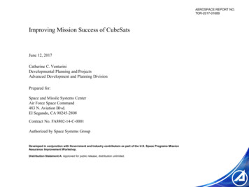
Document: NR-SRD-029Classification: Public DomainNRCSD ICDDate: December 10, 2013Revision 0.36The clearances between NRCSD guide rails and CubeSat rails is shown in Figure 6.Figure 6 CubeSat Rail and NRCSD Rails Clearances ( Z view, Y top).4.6 CubeSat Rails1)2)3)4)A CubeSat shall have four (4) rails, one per corner, along the Z axis.Each rail shall have a minimum width of 6mm 0.1mm/ -0.0mm tolerance.The edges of the rails shall be rounded to a radius of at least 0.5mm /-.1mm.Each rail end face shall have a minimum surface area of 4mm x 4mm for contact with theadjacent CubeSats.5) The minimum extension of the CubeSat rail standoffs beyond the CubeSat /-Z face shall be6.5mm (see Figure 7). NanoRacksPage 10 of 15
Document: NR-SRD-029Classification: Public DomainNRCSD ICDDate: December 10, 2013Revision 0.366) Rail length variance in the Z axis between rails shall not exceed 0.1 mm7) CubeSat rail surfaces that contact the NRCSD guide rails shall have a hardness equal to orgreater than hard anodized aluminum (Rockwell C 65-70).Figure 7 CubeSat Rail Standoff Clearance8) CubeSat developers can verify mechanical compatibility by a fit check with a gauge built to therequirements in Figure 8.Figure 8 Dimensional fit check gauge cross section view NanoRacksPage 11 of 15
Document: NR-SRD-029Classification: Public DomainNRCSD ICDDate: December 10, 2013Revision 0.364.7 Deployment Switches1) CubeSats shall have a minimum of three (3) mechanical deployment switches corresponding toinhibits in the main electrical system (see section on electrical interfaces).2) Deployment switches can be of the pusher variety, located on the –Z face on one or more of therail end faces, or roller/lever switches embedded in a CubeSat rail and riding along the NRCSDguide rail.3) A roller or slider shall be centered on the deployer guide rail, allowing for placement accuracy,the roller or slider shall maintain a minimum of 75% (ratio of roller/slider width-to-guide railwidth) contact along the entire Z-axis (see Figure 9)4) Deployment switches force exerted shall not exceed 3N.Figure 9 Roller/Slider Switch NRCSD Geometry4.8 Separation Springs1) CubeSats, except 6U, shall have separation springs. Separation springs shall be located at the –Zend face of a diagonal pair of CubeSat rails as shown in Figure 10.2) Each spring shall be captive. When compressed the spring shall be contained within themaximum rail length. Separation spring and the rail end face alignment are shown in Figure 11.3) Individual separation spring force shall not exceed 3.34 N (0.75 lbs) with the total force for bothsprings not to exceed 6.67 N (1.5 lbs). NanoRacksPage 12 of 15
Document: NR-SRD-029Classification: Public DomainNRCSD ICDDate: December 10, 2013Revision 0.36Figure 10 Separation spring placement optionsFigure 11 Separation spring rail standoff geometry4.9 Deployment CompatibilityDuring deployment, the CubeSats must be compatible with deployment velocities between 0.5 m/s to1.5 m/s and accelerations no greater than 2g’s in the Z direction.5 Electrical Interfaces5.1 Electrical System DesignThe NRCSD does not accommodate an electrical interface to CubeSats. All electrical power shall beinternal to CubeSats. CubeSat electronics systems design shall adhere to the following requirements. NanoRacksPage 13 of 15
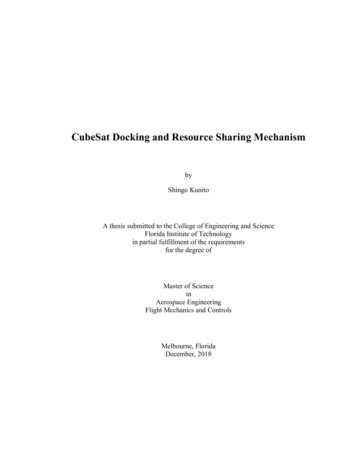
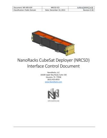
Document: NR-SRD-029Classification: Public DomainNRCSD ICDDate: December 10, 2013Revision 0.361) The CubeSat operations shall not begin until a minimum of 30 minutes after deployment fromthe ISS. Only an onboard timer system may be operable during this 30-minute post deploy timeframe.2) The CubeSat electrical system design shall incorporate a minimum of three (3) inhibit switchesactuated by physical deployment switches (see Deployment Switches section 4.7) as shown inFigure 12.3) The CubeSat electrical system design shall not permit the ground charge circuit to energize thesatellite systems (load), including flight computer (see Figure 12). This restriction applies to allcharging methods.4) RBF pins are required. Arming switch or captive jumpers may be an acceptable alternative;contact NanoRacks.5) The RBF pin shall preclude any power from any source operating any satellite functions with theexception of pre-integration battery charging.6) RBF pins must be capable of remaining in place during integration with NRCSD. It shall not benecessary to remove the RBF to facilitate loading into the NRCSD.7) All RBF pins, switches, or jumpers utilized as primary electrical system and RBF inhibits must beaccessible from the access panels (see Figure 1) for removal at the completion of loading intothe NRCSD.Figure 12 CubeSat Electrical Subsystem Block Diagram (note: RBF switch notshown)5.2 BatteriesCubeSats that utilize on-board batteries shall comply with NASA requirements for battery safety. Thisrequirement applies for main power batteries and for batteries associated with real-time clocks orwatch-dog circuits i.e. “coin cell” batteries. Contact NanoRacks for the appropriate battery testprocedure. Batteries should maintain charge for a minimum of 6 months from time of integration intothe NRCSD by NanoRacks. NanoRacksPage 14 of 15
Document: NR-SRD-029Classification: Public DomainNRCSD ICDDate: December 10, 2013Revision 0.366 Launch LoadsCubeSats shall be tested for random vibration to comply with NASA guidelines per the random vibrationprofile shown in Table 2 .Frequency 002000OA (grms)Hard Mount Configuration (g2/Hz)0.057 (g2/Hz)0 (dB/oct)0.057 (g2/Hz) 7.67 (dB/oct)0.099 (g2/Hz)0 (dB/oct)0.099 (g2/Hz)-1.61 (dB/oct)0.055 (g2/Hz)-3.43 (dB/oct)0.018 (g2/Hz)9.47Table 2 Random Vibration Test Profile7 Thermal InterfacesCubeSats shall be designed to withstand overall temperature range of -40C to 65C.8 Hazardous MaterialsCubeSats shall comply with NASA guidelines for hazardous materials. CubeSat developers shall submit aBill of Materials (BOM) to NanoRacks for assessment.9 CubeSat IntegrationNanoRacks conducts final integration on behalf of the Customer. CubeSat developers shall include theirintegration requirements in memo format along with the CubeSat. NanoRacksPage 15 of 15
The CubeSat center of gravity shall be within 2cm of its geometric center. Table 1 CubeSat Mass Properties Form Factor Maximum Mass (Kg) 1U 2.82 2U 5.657 3U 8.485 4U 11.314 5U 14.142 6U 16.971 4.5 CubeSat Dimensional Requirements CubeSats nominal envelope maximum dimensions are shown in Figure 5. No external components other