Transcription
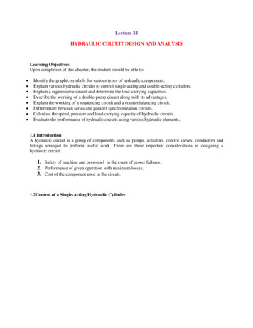
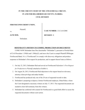
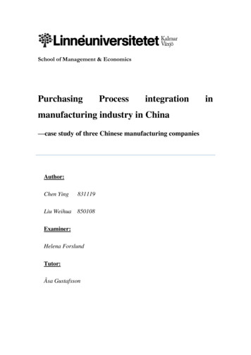
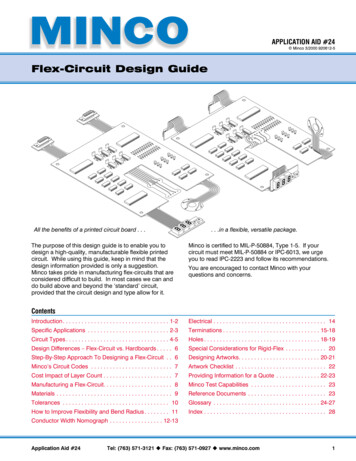
HYDRAULIC CIRCUIT DESIGN AND ANALYSISA Hydraulic circuit is a group of components such as pumps, actuators, andcontrol valves so arranged that they will perform a useful task. When analyzing ordesigning a hydraulic circuit, the following three important considerations must be takeninto account:1. Safety of operation2. Performance of desired function3. Efficiency of operationIt is very important for the fluid power ( Hydraulics and Pneumatics ) designer tohave a working knowledge of components and how they operate in a circuit.Hydraulic circuits are developed through the use of graphical symbols for allcomponents. The symbols have to conform to the ANSI specification.5.1 Control of a Single- Acting Hydraulic Cylinder :A single-acting cylinder can exert a force in only the extending directionas fluid from the pump enters the blank end of the cylinder ( usually left side of thepiston). Single- acting cylinder do not retract hydraulically. Retraction is accomplishedby using gravity or by the inclusion of a compression spring in the rod end.AFig 5.1 SymbolForce during extension stroke is , Fext p * APVelocity during extension stroke is , vP ext QP / APThe force and velocity during retraction stroke depends upon spring rate assingle – acting cylinder do not retract hydraulicallyFigure 5.2 shows a two- postion, three way, manually operated, spring offsetdirectional control valve ( DCV ) used to control the operation of a single – actingcylinder. In the spring offset mode, full pump flow goes the tank via the pressure reliefvalve. The spring in the rod end of the cylinder retracts the piston as oil from the blankend ‘A’ drains back to the rank. When the valve is manually actuated the pump flowgoes to the cylinder blank end ‘A’ via DCV 1 position. This extends the cylinder. At fullextension, pump flow goes through the relief valve. Deactivation of the DCV allows thecylinder to retract as the DCV shift into its spring – offset mode.
CA10DPTEPRTFTFig 5.2. Control of Single -Acting Hydraulic Cylinder.C Single acting cylinderP PumpE Electric MotorT TankF FilterR Relief ValveD 2-position, 3 way DCV Manually operated and springreturn5.2Control of Double -Acting Hydraulic Cylinder :Double –Acting cylinders can be extended and retracted hydraulically. Thus, anoutput force can be applied in two directions.ABFig 5.3 Double acting cylinder
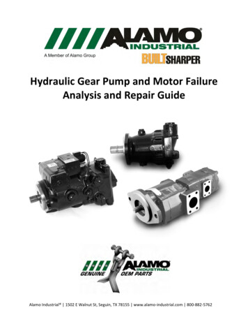
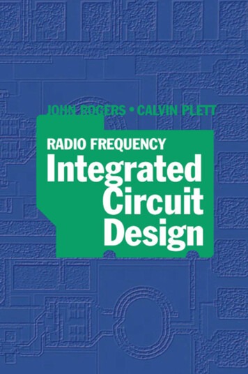
The output force ( F ) and piston velocity of double acting cylinder are not thesame for extension and retraction strokes. During the extension stroke, fluid enters theblank end ( A ) of the cylinder through the entire circular area of the piston ( AP ).However during the retraction stroke, fluid enters the rod end through the smallerannular area between the rod and cylinder bore ( AP – AR ), where AP piston area , andAR rod area. Since AP is grreater than ( AP – AR ), the retraction velocity is greater thanthe extension velocity since the pump flow rate is constant.Similarly during the extension stroke, fluid pressure bears on the entire area ofthe piston( AP ). However during the retraction stroke, fluid pressure bears on the smallerannular area ( AP – AR ). The difference in area accounts for the difference in outputforce, with the output force is greater during extension.Extending stroke :Force, Fext p * AP -------- 1Velocity, vext Qp / AP -----2Retraction Stroke :Force, Fret p * ( AP – Ar ) --- 3Velocity, vret Qp / (AP – Ar ) --- 4It can be seen from the above 4 equations that force during extensionstroke and velocity of piston during retraction stroke is greater for the same operatingpressure and flow rate.The power developed by a hydraulic cylinder for either the extension or retractionstroke, can be found out by (velocity multiplied by force) or from ( flow rate multipliedby operating pressure )Power ( kW ) vp ( m / s )*F ( kN ) Q ( m3 / s)*p ( kPa )Figure 5.4 shows a circuit used to control a double – acting hydraulic cylinder.When the four way valve is in centered configuration , the cylinder is hydraulicallylocked as the ports A and B is blocked. The pump flow is unloaded back to the tank atessentially atmospheric pressure.When the four way valve is actuated into the 1st position , the cylinder is extendedagainst its load force Fload as oil flows to the blank end of the cylinder from port Pthrough port A . Also, oil in the rod end of the cylinder is free to flow back to the tank viathe four way valve from port B through port T. Note that the cylinder would not extendif this oil were not allowed to leave the rod end of the cylinder.When the four way valve is actuated into the 2st position , the cylinder is retractsagainst as oil flows to the rod end of the cylinder from port P through port B. Oil in theblank end of the cylinder is returned to the tank from port A to port T.At the end of the stroke, there is no system demand for oil. Thus, the pump flow goesthrough the relief valve at its pressure- level setting unless the four- way valve isdeactivated. In any event the system is protected from any cylinder overloads.
F LOADCA1B0D2PEPTRTFTFig 5.4. Control of Double -acting hydraulic cylinder.C Double acting cylinderP PumpE Electric MotorT TankF FilterR Relief ValveD 3-position, 4 way ,Tandem center, Manually operated andSpring Centered DCVProblem 1. A double acting cylinder is hooked up to reciprocate. The relief valve settingis 70 bars. The piston area is 0.016 m2 and the rod area is 0.0045 m2. If the pump flow is0.0013m3 / s, find the cylinder speed and load- carrying capacity for thea. Extending strokeb. Retracting stroke.Solution:Relief valve pressure setting, p 70 bars 70 * 105 N /m2Piston area, Ap 0.016 m2Rod area, Ar 0.0045 m2
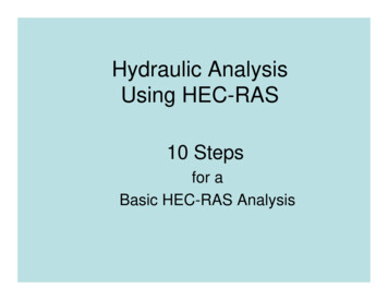
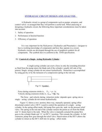
Pump flow, Qp 0.0013 m3/sa) Extending Stroke:Cylinder speed, vp ext Qp / AP 0.0013 / 0.016 0.0813 m / sLoad carrying capacity, Fload p * AP 70 * 105 * 0.016 112000 N 112kNb)Retracting Stroke:Cylinder Speed, vp Ret Qp /(AP – Ar) 0.0013 / ( 0.016 - 0.0045 ) 0.113 m / sLoad carrying capacity, Fload p * ( AP – Ar ) 70 * 105 * ( 0.016 - 0.0045 80500 N 80.5kN5.3 Regenerative circuit:OperationFigure 5.5 shows a regenerative circuit that is used to speed up the extendingspeed of a double-acting hydraulic cylinder. Here the pipelines to both ends of thehydraulic cylinder are connected to pump, one end (A) through the 2 / 3 way DCV andthe other end (B) directly. The operation of the cylinder during the retraction stroke is thesame as that of a regular double-acting cylinder. Fluid flows through the DCV zeroposition from the actuator A side during retraction. In this position, fluid from the pumpdirectly enters the rod end of the cylinder ( direct connection). Fluid in the blank enddrains back to the tank through the DCV as the cylinder retracts.When the DCV is shifted to 1 position due to manual actuation, the cylinderextends. The speed of extension is greater than that for a regular double-acting cylinderbecause flow from the rod end (QR) regenerates with the pump flow (QP) to provide atotal flow rate (QT), which is greater than the pump flow rate to the A side of the cylinder.( Area of blank end is more than rod end, thereby blank end provide least resistance )C
A1B0DPETPFTFig 5.5. Regenerative circuit.C Double acting cylinderP PumpE Electric MotorT TankF FilterR Relief ValveD 2-position, 3 way , Manually operated andSpring return DCVCylinder Extending SpeedThe total flow rate entering the blank end (A) of the cylinder equals the pumpflow rate plus the regenerative flow rate coming from the rod end of the cylinder:QT QP QROrQP QT - QR ---(1)We know that the total flow rate equals the piston area multiplied by theextending speed of the piston (Vpext). Similarly, the regenerative flow rate equals thedifference of the piston and rod areas (Ap - Ar) multiplied by the extending speed of thepiston. Substituting these two relationships into the eq (1) yieldsQP ApVpext – (Ap – Ar)VpextTherefore,QP ArVpext
Hence the extending speed of the piston, V pext QpAr--- (2)Thus the extending speed equals the pump flow divided by the rod area. Thus, asmall rod area (which produces a large regenerative flow) provides a large extendingspeed. In fact the extending speed can be greater than the retracting speed if the rod areais made small enough.Ratio of Extending and Retracting SpeedsLet’s determine under what condition the extending and retracting speeds are equal.We know that the retracting speed (Vpret) equals the pump flow divided by the differenceof the piston and rod areas:V pret Dividing eq(1) with (4) we haveQpA p Ar---(3)A p ArVp extQp / Ar Vp retQp /( Ap Ar )ArSimplifying we obtain the ratio of extension speedand retracting speedVp extAp 1Vp retAr--(4)We see that when the piston area equals two times the rod area, the extension andretraction speeds are equal. In general, the greater the ratio of piston area to rod area, thegreater the ratio of extending speed to retracting speed.Load-Carrying Capacity during Extension :It should be noted that the load-carrying capacity of a regenerativecylinder during extension is less than that obtained from a regular double-acting cylinder.The load-carrying capacity (Fload) for a regenerative cylinder equals the pressuremultiplied by piston rod area rather than the pressure multiplied by piston area. This isdue to the same system pressure acting on both sides of the piston during the extendingstroke of the regenerative cylinder.ThusFload PArThus, the power obtained from the regenerative cylinder is less because theextending speed is increased at the expense of load-carrying capacity.
5.4 Regenerative center in Drilling Machine:F LOADCABC – Double acting cylinderD – 3 Position, 4 Way,10DP2Regenerative center,Tsolenoid actuated,spring centered DCVR – Relief ValveERPFF - FilterE – Electric MotorTTT- TankP - PumpFig 5.6 Application in Drilling MachineFigure 5.6 shows an application of regenerative circuit in a drilling machine. Here a3-position, 4-way , regenerative center directional control valve is used.When the DCV is in the spring-centered position, port P is connected to A and B andtank port T is blocked. In this position pump flow goes to A and flow from rod end ofthe cylinder also joins the pump flow to gives rapid spindle advance ( no work is doneduring this period )Why does the spring-centered position give rapid extension of the cylinder (drillspindle)? The reason is simple. Oil from the rod end regenerates with the pump flowgoing to the blank end. This effectively increases pump flow to the blank end of thecylinder during the spring-centered mode of operation. Once again we have aregenerative cylinder. It should be noted that the cylinder used in a regenerative circuit isactually a regular double-acting cylinder. What makes it a regenerative cylinder is theway it is hooked up in the circuit. The blank and rod ends are connected in parallelduring the extending stroke of a regenerative center.When the DCV shifts to 1st position, P is connected to A and B to T gives slow feed(extension) when the drill starts to cut into the work piece. Similarly when the DCVshifts to 2nd position, P is connected to B and A is connected to T, since the ring area isless the cylinder will have fast return motion.
Problem 2. A double acting cylinder is hooked up in the regenerative circuit. The reliefvalve setting is 70 bars. The piston area is 0.016 m2 and the rod area is 0.0045 m2. If thepump flow is 0.0013m3 / s, find the cylinder speed and load- carrying capacity for thea. Extending strokeb. Retracting stroke.Solution:Relief valve pressure setting, p 70 bars 70 * 105 N /m2Piston area, Ap 0.016 m2Rod area, Ar 0.0045 m2Pump flow, Qp 0.0013 m3/sc) Extending Stroke:Cylinder speed, vp ext Qp / Ar(Regenerative Speed) 0.0013 / 0.0045 0.29 m / sLoad carrying capacity, Fload p * Ar 70 * 105 * 0.0045 31500 N 31.5kNd) Retracting Stroke:Cylinder Speed, vp Ret Qp / (AP – Ar) 0.0013 / ( 0.016 - 0.0045 ) 0.113 m / sLoad carrying capacity, Fload p * ( AP – Ar ) 70 * 105 * ( 0.016 - 0.0045 80500 N 80.5kN3. A double acting cylinder is hooked up in the regenerative circuit. The relief valvesetting is 100 bars and the pump flow is 0.0016m3 / s. If the regenerative and retractingspeed are equal to 0.25m/ s, find the piston and rod area and also load- carrying capacityfor thea. Extending strokeb. Retracting strokeSolution:Relief valve pressure setting, p 105 bars 105 * 105 N /m2Pump flow, Qp 0.0016 m3/s, Speed 0.25 m/ svp ext Qp / Qp / vp extWe have regenerative cylinder speed,Therefore Rod area, Ar 0.0016 / 0.25 0.0064m2Piston Area, AP 2 Ar 2* 0.0064 0.0128 m2Ar
a) Extending Stroke:Load carrying capacity, Fload p * Ar 105 * 105 * 0.0064 67200 N 67.2kNb) Retracting Stroke:Load carrying capacity, Fload p * ( AP – Ar ) 105 * 105 * ( 0.0128 - 0.0065 ) 67200 N 67.2kN5.5 Pump – unloading circuit :F LOADCA1B0DP2TCVPUFTTFig 5.7. Pump unloading circuit.C Double acting cylinderP PumpT TankF FilterU unloadingValve
D 3-position, 4 way ,closed center, Manually operated andSpring Centered DCVIn Fig. 5.7 we see a circuit using an unloading valve to unload a pump. The unloadingvalve opens when the cylinder reaches the end of its extension stroke because the checkvalve keeps high-pressure oil in the pilot line of the unloading valve. When the DCV isshifted to retract the cylinder, the motion of the piston reduces the pressure in the pilotline of the unloading valve. This resets the unloading valve until the cylinder is fullyretracted, at which point the unloading valve unloads the pump. Thus, the unloadingvalve unloads the pump at the ends of the extending and retraction strokes as well as inthe spring-centered position of the DCV.5.6 Double Pump Hydraulic system ( Hi – Lo circuit )F LOADCAB012DPTCVRP1P2UTTFFFig 5.8 Double pump Hydraulic systemP1 -- Low discharge, High pressure
It is very important for the fluid power ( Hydraulics and Pneumatics ) designer to have a working knowledge of components and how they operate in a circuit. Hydraulic circuits are developed through the use of graphical symbols for all components. The symbols have to conform to the ANSI specification. 5.1 Control of a Single-Acting Hydraulic Cylinder: A single-acting cylinder can exert a force .