Transcription
Thermal analysis of Printed Circuit Boardsfor airborne applicationsDiana WilhelmssonMaster of Science Thesis 2017KTH Industrial Engineering and ManagementMachine DesignSE-100 44 STOCKHOLM
Examensarbete 2017Termisk analys av kretskort för flygandeändamålDiana WilhelmssonGodkäntAkademisk handledareHandledareStefan WallinDaniel BengtssonUppdragsgivareKontaktpersonSAABKarin FröderbergSammanfattningSAAB tar fram och tillverkar kretskort för flygande ändamål. Då kylförsörjningen inte sällan ärbegränsad och effektförlusten hög är kretskortens termiska prestanda en viktig parameter attutvärdera. Detta examensarbete är ett steg i en större utvärdering av de Finita Element Modellerna(FEM) som används vid termisk analys av korten. Utvärderingen syftar till att skapa störreförståelse för osäkerheter i nuvarande modeller samt att ge nya förslag på hur modellerna kanförbättras.1
Master of Science Thesis 2017Thermal analysis of PCBs for airborneapplicationsDiana WilhelmssonGodkäntAkademisk handledareHandledareStefan WallinDaniel BengtssonUppdragsgivareKontaktpersonSAABKarin FröderbergAbstractSaab develops and manufactures Printed Circuit Board (PCB) for airborne applications. Since thecooling supply often is limited and power dissipation is high the thermal performance of the PCBsis an important parameter to evaluate. This thesis is a step in a larger evaluation of the FiniteElement Methods (FEM) used for thermal analysis of the cards. The evaluation aims to creategreater understanding of the uncertainties in current models and to provide new proposals on howthe models can be improved.2
FOREWORDDuring the course of my work, I have been helped by my supervisor Daniel Bengtsson andcolleagues at SAAB and I am incredibly grateful for everything I have learned during this timeand the support. My academic supervisor Stafan Wallin has also been supportive with providinghelpful feedback on my CFD result.Diana WilhelmssonStockholm, June 20173
��𝑁𝑢nnp𝑃𝑟𝑄̇𝑞̇𝑞̇ 𝑣𝑅R𝑆𝑇𝑇𝑇𝑏𝑜𝑑𝑦𝑇 𝑉𝑥𝑦𝑧AreaEquivalent diameterSpecific heatSpecific heat capacityBody forceGravitational accelerationGrashof numberHeat transfer coefficientThermal conductivityThermal conductivityCharacteristic lengthNusselt numberNormal vectorNumber of molesPressurePradtl numberHeat flowHeat fluxHeat generationThermal contact resistanceUniversal gas constantSurfaceTemperatureSymmetric tensorBody temperatureFreestream temperatureVolumex- coordinatey- coordinatez- ��Volume coefficient of expansionBoundary layer thicknessTemperature differenceThermal resistanceKinematic viscosityDynamic viscosityDensityStefan-Boltzmann’s 4]4
𝜆𝜏Equivalent Thermal conductivityStress CBSPUComputer Aided Engineering softwareBoundary ConditionDetailed Thermal ModelComputational Fluid DynamicsCompact Thermal ModelElectronic Warfare Central UnitFinite Element MethodField-Programmable Gate Array (integrated circuit)Finite Volume MethodPrinted Circuit BoardSeparate Portable Unit5[W/mK][Pa]
TABLE OF RE4TABLE OF CONTENTS61 INTRODUCTION81.1 Purpose81.2 Delimitations82 FRAME OF REFERENCE92. Operation condition92.1 Printed circuit board102.1.1 PCB modelling112.2 Heat transfer122.2.1 Thermal conduction132.2.2 Convection132.2.3 Thermal radiation152.3 Power dissipation of components152.4 FVM-analysis162.4.1 Fluid dynamics163 METHOD193.1 Modelling193.1.1 Thermal analysis193.1.2 PCB modelling203.1.3 Modelling of components213.1.4 Experiment setup233.1.5 CFD modelling of fluids244 RESULT AND DISCUSSION274.1 Thermal analysis of the PCB274.2 Experimental result344.3 CFD result346
5 CONCLUSION396 RECOMMENDATION AND FUTURE WORK407 REFERENCES41APPENDIX A: BOARD LEYER SPECIFICATION43APPENDIX B: BOARD LAYOUT44APPENDIX C: VIA LAYOUT46APPENDIX D: GAP PAD POSITION48APPENDIX E: POWER DISSIPATION49APPENDIX F: POWER DISSIPATION50APPENDIX G: THERMAL CONDUCTIVITY51APPENDIX H: MATLAB CODE52APPENDIX I: INDATA TO MATLAB CODE557
1 INTRODUCTION1.1 PurposeSaab develops and manufactures Printed Circuit Boards (PCBs) for airborne applications. Sincethe cooling supply often is limited and power dissipation is high the thermal performance of thePCBs is an important parameter to evaluate. This thesis is a step in a larger evaluation of the FiniteElement Methods (FEM) used for thermal analysis of the cards. The evaluation aims to creategreater understanding of the uncertainties in current models and to provide new proposals on howthe models can be improved.1.2 DelimitationsThere is limitation in the experimental setup and verification of the models due to an uncertaintyof power dissipation of the components on the card.8
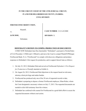
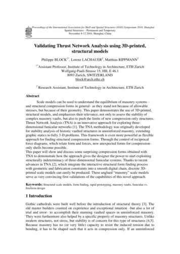
2 FRAME OF REFERENCE2. Operation conditionThe Gripen Next Generation has an integrated Electronic Warfare Central Unit (EWCU) which islocated inside the aircraft fuselage. One of the EWCU PCBs will be investigated in terms ofthermal analysis. Figure 1 illustrates the location of the EWCU.Figure 1. Operation conditions EWCUEWCU is a closed chassis unit with air cooled edges that has contact with the PCB as seen inFigure 2. The cooled air will flow inside the wall as the arrows show in the Figure 2 below.Figure 2. EWCU opened and closed chassisDue to regulations and lack of space, no fan is allowed in this unit to help the cooling of the PCBs.Heat generated at the PCBs is transported by conduction towards the air-cooled walls of thechassis. The same air-cooled principle is used in other systems and applications. As EWCU is aclosed chassis unit the air inside can be expected to be still apart from a small effect from naturalconvection from the heated components. In this report, these effects are believed to be very smalland considered as neglectable. The parameters when calculating natural convection are also hardto estimate and could give a wrong result. The PCB that will be analysed in this report is the thirdPCB from the top in Figure 3 of the EWCU.9
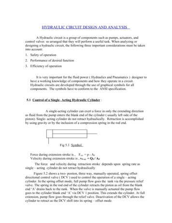
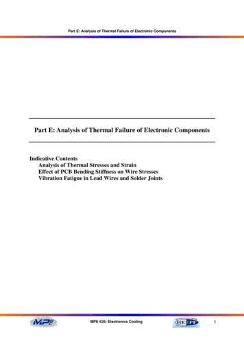
Figure 3. Inside EWCU2.1 Printed circuit boardPrinted circuit boards (PCB) are used in all kinds of electronic applications such as computers, cellphones, stereos etc. One of the benefits coming from the usage of PCBs are that the electroniccircuits can be more compact, smaller and placed on an appropriate thin board. The boardstypically consist of an insulating glass epoxy material such as FR-4 with thin layer of copper foillaminated to one or both sides. Plated holes/vias are drilled down to the desired layer to ensureconnection between the components and to the ground plane. With the through hole technology,each component has leads that is pushed through holes and soldered to connection pads in thecircuit on the opposite side. Another method which is used is the “surface mounted method” wherethe components are connected directly to the printed circuit though J-shaped or L-shaped legs onthe component (How Product are Made 2017).Figure 4. Through hole device, through hole resistor, surface mounted components (Wikipedia Through holetechnology 2017) (Wikipedia Surface mount Thechnology 2017)Ball grid array (BGA) surface mounted technology is used for printed circuits with a large numberof pins. The method uses the underside of the package where pins are placed on the underside ofthe chip in a grid pattern as seen in the Figure 5 below (Poole 2017).10
Figure 5. Ball grid array BGABGAs are often designed with low thermal resistance upwards so that heat can be transported toattached heat sinks. Some BGAs also have a thermal pad at the bottom. This thermal pad issoldered to the PCB facilitating heat transfer in the board direction. Additionally, the ballsthemselves contribute to heat transport, foremost those connected to any of the PCBs groundplanes. When thermally modelling a PCB, it is important to understand the mechanism of heattransfer of the components since they have different impacts on the PCB’s thermal properties, atleast when a simplified PCB model is used. Not all vias contribute to heat transport the same.Field-Programmable Gate Arrays (FPGAs) are reprogrammable silicon chips (NationalInstruments 2017). FPGAs are a combination of the best part of Application- Specific IntegratedCircuits (ASICs) and processor based system. FPGAs don’t need high volumes to providehardware speed and reliability like expensive ASIC design. They are also not limited by thenumber of processing cores available and are flexible in regards to the software running on aprocessor- based system. These components are very popular today and is one of the mostimportant component in these analysis.2.1.1 PCB modellingThere is a trade-off when it comes to thermal analysis of PCBs. Higher accuracy comes with highercomputational cost. Higher accuracy usually means longer time for the calculations and themodelling. There are several methods to model PCBs and the importance of having accuracy inregards to the effort required to gain accuracy needs to be considered. A detailed model can beused where the physical geometry of the package is reconstructed by integrating mechanical CADdata for the parts. With the program ANSYS a more complex model could be set up by using theoverall flow in the Figure 6 below (Dillinger 2016).Figure 6. ANSYS R17.0 workflow (Dillinger 2016)The RedHawk tool suite generates Chip Power Model (CPM) and Chip Thermal Model (CTM)abstracts. The SIwave suite has the DC PDN analysis feature which is used to derive thepackage/board DC current distribution throughout the plane layers. These currents contribute toresistive power loses and temperature gradients. A CFD analysis is done by ANSYS Icepak todetermine a complete thermal profile with the help of SIwave DC result for the PDN and the ChipThermal Models. The Figure below illustrates how a result from Icepak could look like (Dillinger2016). As seen in the Figure 7 the result is very detailed.11
Figure 7.Icepak thermal profile (Dillinger 2016)A detailed thermal model (DTM) will precisely predict the temperatures of the board. Thetemperature in the model can be predicted at several points within the packages including junction,case and lead temperatures. This type of modelling is appropriate when the number of package isfew due to the high computational time and cost (Advance Thermal Solutions, INC 2017).In this report, a Compact Thermal Model (CTM) is used where the model aims to predict thetemperature at only the critical points, junction case and leads. This is done using much lesscomputational effort as the model will not import the correct physical geometry and data. It willuse simplified geometry of the board and the components (Advance Thermal Solutions, INC2017). In this model, the board material will be homogenized and the components will be modelledaccording to the contact are of the board. The model will also use a thermal resistor network suchas the two-resistor model to model the components which is describe in more detailed in themethod section of this report. The two-resistor model is commonly used for CTMs.2.2 Heat transferHeat transfer is related to the first law of thermodynamics which is an equation describingconservation of energy. The internal energy of a system must be the sum of all input energy andoutput energy. Heat transfer occurs when a temperature difference exists within a system orbetween systems in thermal contact to each other. The three modes of heat transfer are thermalconduction, convection and thermal radiation that are illustrated below (Peter von Böckh 2012).Figure 8. Thermal conduction, convection and thermal radiationThe heat flow/heat rate 𝑄̇ is the amount of heat transferred per unit time with the dimension Watt[W]. The heat flux density 𝑞̇ 𝑄̇ /𝐴 is defined as the heat rate per unit area and has the dimensionWatt per square meter [W/m2]. 𝜗 is defined as the temperature.12
2.2.1 Thermal conductionThermal conductivity is a material property and a measure of how well the material can transferheat. Heat transfer between a solid wall and a moving fluid develops by the thermal conductionbetween the wall and the fluid and within the fluid (Peter von Böckh 2012).The thermal conductivity constant 𝑘 is determined from Fourier’s law where the heat flux isproportional to the temperature gradient (Malhammar 2005) 𝜗 𝜗 𝜗(𝑘𝑥 ) (𝑘𝑦 ) (𝑘𝑧 ) 𝑞̇ 𝑣 0 𝑥 𝑥 𝑦 𝑦 𝑧 𝑧(1)which can be simplified for material that is not coordinate dependant to𝑘𝑥 2𝜗 2𝜗 2𝜗 𝑘 𝑘 𝑞̇ 𝑣 0𝑦𝑧 𝑥 2 𝑦 2 𝑧 2(2)and this is sometimes the case for the laminated structures in PCBs. For the case that the thermalconductivity is the same in all direction equation (1) can be simplified furthermore to 2𝜗 2𝜗 2𝜗𝐾 ( 2 2 2 ) 𝑞̇ 𝑣 0 𝑥 𝑦 𝑧(3)In some more complicated cases the material in electronics like semi-conductors can havetemperature dependant thermal conductivity. For those cases it is more convenient to formulateequation (1) with the absolute temperature as independent variable according to (Malhammar2005) 2𝑇 2𝑇 2𝑇(4)𝐾(𝑇) ( 2 2 2 ) 𝑞̇ 𝑣 0 𝑥 𝑦 𝑧2.2.2 ConvectionHeat convection is a phenomenon that occurs when heat is moved with the help of fluids. Thismovement arises naturally from density variation and with the help of the gravity or could beforced with the help of for example a fan or a pump. In the natural case an example could be aheated component that creates density variations within the surrounding fluid as less densemolecules are formed. The less dense molecules will be rising as they are lighter and the densermolecules will move down as seen in the left Figure 9 below (Mathematik in denNaturwissenschaften 2017) (John H. Lienhard IV u.d.).Figure 9. Natural & forced convection13
In the right side of Figure 9, a cool gas flows over a warm body and h
important component in these analysis. 2.1.1 PCB modelling There is a trade-off when it comes to thermal analysis of PCBs. Higher accuracy comes with higher computational cost. Higher accuracy usually means longer time for the calculations and the modelling. There are several methods to model PCBs and the importance of having accuracy in