Transcription
Basics of Flex Circuit DesignMark Finstad, Principal Applications Engineer, Flex Circuits Division, Minco
Table of ContentsAbstract . . . . . . . . . . . . . . . . . . . . . . . . . . . . . . . . . . . . . . . . . . . . . . . . . . . . . . . . . . . . . . . . . . . . . . . . . . . . . . . . . . . . . . . . . . . . . . . Page 3Critical Factors . . . . . . . . . . . . . . . . . . . . . . . . . . . . . . . . . . . . . . . . . . . . . . . . . . . . . . . . . . . . . . . . . . . . . . . . . . . . . . . . . . . . . . . . . Page 4Creating a Reliable Design . . . . . . . . . . . . . . . . . . . . . . . . . . . . . . . . . . . . . . . . . . . . . . . . . . . . . . . . . . . . . . . . . . . . . . . . . . . . . Page 5Neutral Bend Axis . . . . . . . . . . . . . . . . . . . . . . . . . . . . . . . . . . . . . . . . . . . . . . . . . . . . . . . . . . . . . . . . . . . . . . . . . . . . . . . . . . Page 5Bend Angle . . . . . . . . . . . . . . . . . . . . . . . . . . . . . . . . . . . . . . . . . . . . . . . . . . . . . . . . . . . . . . . . . . . . . . . . . . . . . . . . . . . . . . . . Page 5Thickness . . . . . . . . . . . . . . . . . . . . . . . . . . . . . . . . . . . . . . . . . . . . . . . . . . . . . . . . . . . . . . . . . . . . . . . . . . . . . . . . . . . . . . . . . . Page 6Bend Radius . . . . . . . . . . . . . . . . . . . . . . . . . . . . . . . . . . . . . . . . . . . . . . . . . . . . . . . . . . . . . . . . . . . . . . . . . . . . . . . . . . . . . . . Page 6Bend Ratio . . . . . . . . . . . . . . . . . . . . . . . . . . . . . . . . . . . . . . . . . . . . . . . . . . . . . . . . . . . . . . . . . . . . . . . . . . . . . . . . . . . . . . . . . Page 7Static vs. Dynamic Applications . . . . . . . . . . . . . . . . . . . . . . . . . . . . . . . . . . . . . . . . . . . . . . . . . . . . . . . . . . . . . . . . . . . . . Page 7Materials and Construction . . . . . . . . . . . . . . . . . . . . . . . . . . . . . . . . . . . . . . . . . . . . . . . . . . . . . . . . . . . . . . . . . . . . . . . . . Page 8Tips and Tricks. . . . . . . . . . . . . . . . . . . . . . . . . . . . . . . . . . . . . . . . . . . . . . . . . . . . . . . . . . . . . . . . . . . . . . . . . . . . . . . . . . . . . . . . page 10Summary. . . . . . . . . . . . . . . . . . . . . . . . . . . . . . . . . . . . . . . . . . . . . . . . . . . . . . . . . . . . . . . . . . . . . . . . . . . . . . . . . . . . . . . . . . . . . Page 11Copyright 2008, MincoPage 2
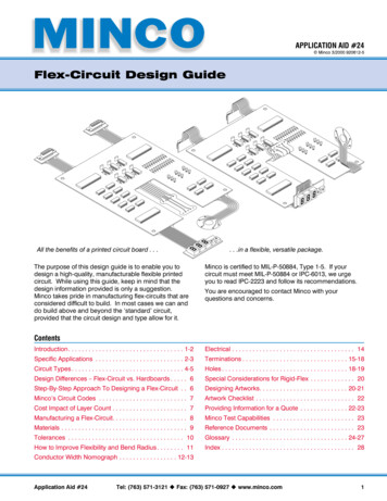
AbstractFlex circuitry is ideal for many of today’s electronics needs. It is light, compact, and, if properly designed,extremely robust. Because it bends, however, a flex circuit has some very specific requirements that aredifferent from those of traditional rigid circuits. Materials, circuit architecture, placement of features, and thenumber of layers in the circuit must all be considered in the design process. So must the degree to which thecircuit will be bent, how tight the bend will be, how the bend will be formed, and how frequently the circuitwill be flexed. By carefully defining the application and design priorities and recognizing the unique demandsmade upon flex circuits, the designer can work within these requirements to realize the technology’s fullpotential.There are plenty of good reasons to use flex circuits. They are light, compact, robust, and resilient, and ideal fortoday’s smaller and more portable electronics. They are ideal for new product designs, but can be used toreplace traditional wire harnesses and circuit boards as well. But to realize their full potential, designers mustconsider the unique requirements of these circuits and the materials they are made of. It is important torecognize that, while the materials that comprise a flex circuit may be individually flexible, their performancein a completed circuit is greatly impacted by a circuit’s construction.Single Layer Flex Bent 90 DegreesFigure 1: A circuit’s neutral bendaxis, ideally located on the centralplane of the material stack,experiences none of the tension orcompression that affect otherlayers when the circuit is bentEvery flex circuit has a neutral bend axis. This plane, which is ideally located on the central plane of the materialstack, experiences, at least in theory, no compression or tension forces when the circuit is flexed. Toward theoutside of the bend, however, outer layers experience increasing tension, which can tear or crack the materials.This can lead to immediate circuit failure or, potentially worse, hairline breaks that will fail after the circuit hasbeen put into service. Toward the inside of the bend, layers are subject to increasing compression. This cancause layers to wrinkle or delaminate, again a potential cause of immediate or eventual failure. Careful designcan help prevent these problems.Figure 2: If a circuit is not properlydesigned and handled, outerlayers can tear or crack and innerlayers can wrinkle or delaminateCopyright 2008, MincoPage 3
Critical FactorsA variety of factors can impact a circuit’s performance when flexed. These include: The closer the neutral bend axis falls to the center of the circuit’s material stack, the moreevenly forces will be distributed among the other layers of the circuit when it is flexed Bend angle – the less a circuit is flexed, the smaller the risk of damage Thickness of the circuit – less thickness reduces the risk of damage when flexed Bend radius – a larger radius helps reduce the risk of damage Frequency of flexing – construction that might not be acceptable for a dynamic application,one in which the circuit will be flexed regularly, may be acceptable in a circuit designed tobend only once for installation Materials – proper selection of materials for their ability to accommodate flex and the waythey transmit those forces to other layers in the bend area will improve performance Construction – designers should avoid placement in or near the bend area of features thatare particularly vulnerable to forces generated in the bend area, or that can weakensurrounding circuit structure when flexedCopyright 2008, MincoPage 4
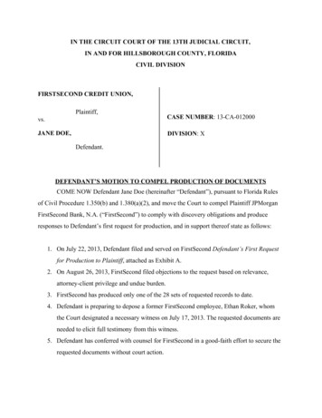
Creating a Reliable DesignFlex circuitry is a powerful technology, but like any technology, it involves tradeoffs. The designer’s goal is toproduce a robust and effective circuit that meets performance goals and fits space and weight requirements atthe lowest price. Balancing these various expectations depends on a clear understanding of the factors thataffect flex circuit performance.Neutral Bend AxisThis is a key concept in flexible circuit design. The neutral bend axis is the plane within the circuit where there isneither compression nor tension when the circuit is flexed. The amount of tension or compression on the outerlayers of the circuit depend on their distance from this neutral bend axis. The only way to keep both thesedistances, and the potentially damaging forces that result, as small as possible is to get the neutral bend axis asclose as possible to the middle of the stack.The best way to center the neutral bend axis is through balanced construction. It may help to envision theneutral bend axis as an imaginary plane that may or may not coincide with an actual structure within thecircuit. A heavy copper plane, a layer of heavy copper conductors, or a thick layer of polyimide dielectric( .003”) will shift the neutral bend axis toward that face of the circuit. By balancing the placement of suchlayers above and below the center plane of the material stack, a designer can equalize the distance from theneutral bend axis of the circuit’s outer layers and minimize stretching and compressing forces at these surfacesin the circuit’s bend area.Bend AngleAll other factors being equal, the forces created when a circuit is flexed—tension on the outside andcompression on the inside of a bend—increase with the angle of the bend. For this reason, a circuit should beflexed no more than necessary to achieve the goals of the design. In general, 90 is considered the maximumangle through which any circuit should be bent more than once. In certain cases, a properly designed circuitmay be bent more than 90 once, for installation. But if the application is dynamic—if the circuit will be flexed,flattened, and re-flexed multiple times—the bend should not exceed 90 .The way a circuit is formed (bent for installation) can be critical. If circuits are formed by hand rather than with aforming tool, they can easily be bent unevenly, so that some areas of the bend exceed acceptable bend angles.It is preferable to use a forming tool that controls every point of the bend when it is formed.Figure 3: The forces created when a circuit isflexed—tension on the outside and compression on the inside of a bend—increase withthe angle of the bendCopyright 2008, MincoFigure 4: Because circuits that are formed byhand can be bent unevenly, it is preferable touse a forming tool that controls the bendwhen it is formedPage 5
Also, circuits are sometimes “overformed,” bent beyond their intended bend angle to compensate for materialmemory that will cause them to spring back after forming. If the intended bend is close to the circuit’s limits,overforming should be avoided to prevent damage. This can be done by flexing the circuit to its intended angleand then using some means of holding it at that angle to keep it from springing back.ThicknessSimply put, the thicker the circuit, the less it can flex without damage, so unnecessary thickness should beavoided. At the same time, however, designers should be aware that there is a tradeoff between mechanicalperformance and electrical performance. Keeping a circuit thin, if not done properly, can impact electricalperformance. In some cases, circuit thickness can be reduced without impacting performance, but at someincrease in cost of production.A number of factors affect the thickness of a circuit including the thickness of individual materials, the way theyare put together, and the number of copper layers needed to create the circuit. Ways of reducing circuitthickness in the bend area include reducing the base copper weight and adhesive thickness and reducingdielectric thickness. Designers can also reduce thickness by using adhesiveless base materials.Figure 5: The thicker a circuit is, the lessit can be flexed without damageBend RadiusTighter bends increase the risk of damage to the circuit. In the case of a 90 bend, for example, the same rightangle can often be achieved with a sharp (small radius) angle or a more gradual (large radius) angle. Obviously,the latter is safer for the flex circuit. (Note that bend radius is measured from the inside surface of the bend.)Figure 6: Sharper, i.e., small radius, bends increasethe risk of damage when a circuit is bentCopyright 2008, MincoPage 6
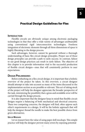
Bend RatioThe reliability of a well-designed flex circuit depends on the ratio of bend radius to circuit thickness. This is the“bend ratio.” Ideally, a multi-layer circuit should have a bend ratio of at least 20:1. For double-sided circuits, theminimum ratio should be at least 10:1. And for single-layer circuits, the minimum ratio should be at least 10:1.These limits assume static applications, in which the circuit will not be flexed after installation. Circuits that areclose to the minimum bend ratio should be constrained once they have been formed to avoid damage due toadditional flexing. Detailed information on safe bend radii for various circuit types and thicknesses can befound in IPC-2223.Figure 7: Bend ratio is the ratio of bend radius to circuit thicknessBecause the IPC standards are conservatively written to take into account many factors that can affect circuitresilience, it is possible to safely achieve lower-than-standard bend ratios. However, due to the number offactors that can affect performance at smaller-than-recommended bend ratios, it is highly advisable thatdesigners work with an experienced flex circuit manufacturer in developing such designs.Static vs. Dynamic ApplicationsThe number of times that a circuit will be flexed is a critical question. The reason is that, after the initial bend,materials in a circuit are subject to different forces than during the first bend. The first time a circuit is flexed,copper layers on the outside of the neutral bend axis are stretched. If minimum bend ratios are adhered to, thisis typically not a problem, since copper is ductile and able to stretch. But if the circuit is then flattened, thestretched copper cannot resume its original shape, so it will ripple. In subsequent bends, these ripples in thecopper are flexed and will work-harden and eventually crack the copper.Similarly, materials on the inside of the neutral bend axis are rippled when flexed and then flattened if the bendis opened. This too can work-harden copper, increasing the likelihood of broken conductors.As mentioned previously, the recommended minimum bend ratios for circuits are for static applications, inwhich the circuit is installed once and never moved again. Semi-static applications are those in which thecircuit does not flex in normal use, but may be flexed as many as 20 times over the life of the circuit when, forexample, it is handled for maintenance or repair. Dynamic applications are those in which the circuit is regularlyflexed, potentially thousands or even millions of times.Circuits designed for dynamic applications should not be more than one layer thick. Their bend ratio must besignificantly larger than the standard ratio recommended for static applications. And the designs should beperfectly balanced, with the conductor—the neutral bend axis—centered between identical top and bottomlayers.Copyright 2008, MincoPage 7
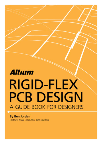
Materials and ConstructionA number of issues should be considered in designing any flex circuit. When routing conductors, note that very smallconductors (less than 10 mils) can tolerate compressionbetter than stretching. For this reason, they should beplaced to the inside of the neutral bend axis. If the circuit incorporates a copper plane layer, thisshould be placed near the center of the material stack tohelp keep the neutral bend axis centered. Avoid plated through holes in the bend area. Near thecenter of the bend, such holes can be stretched on oneside and compressed on the other. Near an end of thebend, the hole can shear. Copper in the holes can crack,and unsupported polyimide insulation over a hole canstretch and crack. Conductors running through a bend area should alwaysrun perpendicular to the bend. Twisting forces on aconductor running at a non-right angle to the bend candamage the conductor. In multi-layer circuits, conductors stacked on top of oneanother increase the effective thickness of the circuit andshould be avoided. If possible, stagger the conductors tolower circuit thickness and the resulting bend ratio.Where signal and return lines are “stacked” in pairs toreduce emitted noise, try to stagger the pairs ofconductors. If you use surface mount (SMT) components, be aware oftheir unique requirements. These usually entail the use ofphoto-imageable coverlay to allow full exposure of thecomponents and adhesiveless base material to preventpad lifting during the reflow process. Circuits alsotypically must be “rigidized” by laminating a stiffener ofthe side of the circuit opposite the SMT. Because of theneed for stiffening, flex circuits usually have SMTcomponents on only one side of the circuit. Theexception is rigid flex circuitry, which often has SMTcomponents of both sides. Rigid flex circuits are stiffenedalong most of their surface, with relatively small areas leftunstiffened to act as hinges or flexible arms.Copyright 2008, MincoFigure 8: Plated through holes located nearthe center of a bend can be stretched on oneside and compressed on the other leading tocircuit failureFigure 9: Conductors running through a bendarea should always run perpendicular to thebend as shown on the left, not at an angle asseen on the rightFigure 10: Because conductors stacked ontop of one another increase the effectivethickness of the circuit, it is preferable tostagger the conductorsPage 8
Avoid “discontinuities” in the bend area. These are weak or stiff points in or near (within .1” of ) the bendarea. Weak areas can be damaged when the circuit is formed. Stiff areas can transfer forces to adjacentareas, creating damage in those other areas. Examples of discontinuities to be avoided in the bend areainclude: plated finishes on conductors, openings in an insulation cover, slits or cut-out areas, or changesin conductor width. Avoid stitched vias. Since flex circuit dielectrics are sothin, stitched vias are of questionable value inprotecting against EMI. If they are incorporated in acircuit design, they should be kept away from the bendarea, as they are discontinuities that can lead to cracksin insulation.Figure 11: Stitched vias, like through holes,should be kept out of bend areaCopyright 2008, MincoPage 9
Tips and TricksThe basic rules of flex circuit design have been tested and proven, but there are a number of ways to workaround standard design limitations: If a circuit’s bend ratio is too small, forces acting in the area can sometimes be reduced by unbondingthe layers in the bend area. This reduces the functional thickness in the bend area; instead of being thetotal thickness of the circuit, the functional thickness becomes the thicknesses of the individual layers.When this is done, the unbonded layers will tend to buckle inward. Their bend radii may be smaller thanthat of the overall bend, but their reduced thickness will significantly lower the overall acceptableminimum bend ratio. Be careful not to unbond too short an area (less than .75”), as the resultingbuckling can lead to unacceptably tight bend radii in the unbonded layers.Figure 12: Potentially damaging forcescan sometimes be reduced by unbondinglayers in the bend areaFigure 13: If the unbonded area is too short(less than .75”) the resulting buckling canlead to unacceptably tight bend radii Another way to help address low bend ratios is to eliminate copper plating on conductors in the bendarea. Copper plating is less ductile than rolled, annealed copper, making it more susceptible to crackingwhen flexed. Selective plating, on pads only, can eliminate plating on flexing conductors. Eliminatingplating in the bend area reduces thickness by eliminating both the thickness of the plating and therequired thickness of the cover adhesive. Selective plating can increase cost, but it may be worth theprice if it prevents circuit failure. Adhesiveless substrates can reduce thickness by .001-.002” per layer. These materials cost somewhatmore than adhesive-based materials but may be worth the cost by eliminating problems in a too-thickcircuit. Dielectrics differ in their ratio of stiffness to thickness. Choose a dielectric material that fits yourapplication and gives your finished circuit the characteristics you want. Unless they are filleted, termination pads can act as a concentration point for stress in a flex circuit. It isgenerally good practice to fillet all termination pads, but this is particularly important in, or within .1” of,bend areas, especially if the cover opening does not entirely capture the pad. If shields or ground planes are required, use a crosshatched pattern instead of solid copper to maximizecircuit flexibility. Openings in the crosshatched shield should be sized in to EMI frequency. Note that ifcontrolled impedance is required, a reduced plane area will significantly increase impedance over that ofa solid plane. Other factors, such as conductor width and dielectric thickness can be adjusted to achievedesired impedance. Another flexible alternative to solid copper for shields is a screen-printed conductive coating such assilver epoxy, which provides similar electrical performance to a copper shield but is much more flexible.Copyright 2008, MincoPage 10
SummaryThe reliability of flex
designers work with an experienced flex circuit manufacturer in developing such designs. Static vs. Dynamic Applications The number of times that a circuit will be flexed is a critical question. The reason is that, after the initial bend, materials in a circuit ar