Transcription
Split plummer block housings SNVFor shaft diameters 20 mm to 160 mmand ¾ inches to 5½ inches
aring seat and fitting of bearings3Seals and covers4Lubrication5Mounting instructions10Additional holes for fixing screws and pins15Load carrying capacity16Ordering examples18Dimension tables20The modifications compared to the previous housing designare clearly shown in publication PDB 1, New generationof SNV housings.
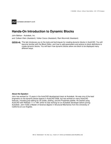
Features · AdvantagesFeaturesSplit FAG housings of series SNV,Figure 1, are designed accordingto a modular concept and area development of the SN/SNEhousings.Rolling bearings of various diameterand width series can be fitted intoeach SNV housing, if they havethe appropriate outside diameterfor the housing, Figure 2.Suitable bearing types includeself-aligning ball bearings, barrelroller bearings, split and unsplitspherical roller bearings and deepgroove ball bearings.The bearings are either seateddirectly on the shaft or are locatedusing adapter sleeves. This givesdifferent shaft diameters for thesame bearing size.aAppropriate seals can compensatethe spaces between shaft andhousing diameter.Split plummer block housings ofthe series SNV are available forshaft diameters 20 mm to 160 mmand ¾ inches to 5½ inches.The digits in the housing desig nation indicate the housing boreand thus the outside diameterof the appropriate bearing,for example 100 mm for SNV100-F-L.AdvantagesAdvantages of housings SNV are: Simplified stockholding as aresult of the modular concept.One housing size suitablefor various shaft diameters.b1: Split plummer block housings of the series SNV; a: SNV052-F to SNV200-F; b: SNV215-F to SNV340-F2 High load carrying capacity. Depending on the operatingconditions, double lip seals,labyrinth seals, felt seals,V ring seals or combined sealsmay be used. Special seals available byagreement. Locating bearings centredby means of two locating ringsof identical width. Flat end faces on the housingbase allow abutment againststops if high forces do not acton the locating face in a purelyvertical direction. Holes can be created at markedpoints on the housing for:monitoring systems, fixingscrews, parallel or tapered pins.
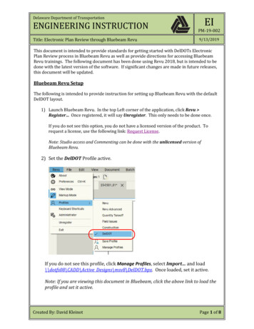
Advantages · Dimensions · Material · Bearing seat ·Fitting of bearings Universal paint coating for allouter surfaces of the housingsnot machined by chip-formingmethods (colour RAL 7031,bluish grey). The coating can befinished using all synthetic resin,polyurethane, acrylic, epoxyresin, chlorinated rubber,nitrocellulose and acid-hardeninghammer tone finishes.DimensionsThe dimensions of housings SNVcorrespond to ISO 113 andto DIN 736 to DIN 739.The housings are interchangeablewith the existing housings SN/SNE.Materialthe delivered condition, i.e. beforethe screws connecting the upperand lower sections are loosened).The bearings are movable and thusfunction as non-locating bearings.Locating bearing arrangements areachieved by inserting one locatingring FRM on each side of thebearing. The bearing is thus seatedin the centre of the housing.The rolling bearings can be seateddirectly on a stepped shaft or on anadapter sleeve and a smooth shaft,Figure 2.If the bearings are located usingan adapter sleeve, diametertolerances of the shaft to h8 (h9)are permissible.The standard material for thehousings SNV is flake graphitecast iron EN-GJL-HB215 (suffix L).The load carrying capacityis considerably higher thanfor SN/SNE housings (see section“Load carrying capacity”).For particularly high loads,we can by agreement supplyhousings made from the materialEN-GJS-400-15 (spheroidal graphitecast iron). These housings areindicated by the suffix D.Bearing seat and fittingof bearingsThe bearing seat in the housingSNV is machined to G7 (valid forØ4010510510510544444444Locating bearingNon-locating 40Locating bearingNon-locating 11SN309SNE2112: SNV housings are suitable for bearings of various diameter and width series, that have the same outside diameter, for example 100 mmfor SNV100-F-L (2a). Previously, the indicated shaft diameters required four different housing sizes (2b).3
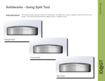
Seals and coversSeals and coversSeals and covers are fitted in therectangular-section annular slotson both sides of housings SNV.The FAG double lip seal DH is themost popular seal. We can alsosupply V ring seals DHV, felt sealsFSV, labyrinth seals TSV, combinedseals TCV and special seals.The seals must be orderedseparately. They are principallysuitable for grease lubrication,see section “Lubrication”.dTSVThe double lip seal DH made fromacrylonitrile butadiene rubber(NBR), Figure 3a, is suitable forcircumferential speeds up to 13 m/s(in continuous operation up tomax. 6 m/s). The two-part seal DHcan be easily inserted in theannular slots in the housing(pay attention to the position ofthe joint). The seal lips slide on therotating shaft. The outer seal lipprevents ingress of contaminationinto the bearing arrangement.This effect is supported by thegrease held between the seal lipsat assembly. The inner lip preventslubricant from escaping from thehousing.aDHThe double lip seal allows shaftmisalignment of up to 0,5 in both directions. It is suitablefor temperatures from –40 Cto 100 C. The contact areaon the shaft for the seal lips shouldhave a roughness to class N8(DIN ISO 1302).In FAG V ring seals DHV made fromNBR, the seal lip is in axial contactwith the sliding surface, Figure 3b.The seal allows misalignmentof up to 0,5 in both directionsand is suitable, if grease lubricationis used, for a circumferential speedup to 12 m/s (at 8 m/s axiallocation is necessary, at 12 m/sadditional radial clamping).efTCVDKVDKVTFSVDHVc3: Seals and covers for SNV housings4bg
Seals and covers · LubricationFAG felt seals FSV, Figure 3c,are suitable for grease lubricationand temperatures up to 100 C.By agreement, aramide packingis available for high temperatures(suffix G600).The adapter holding the inserted,oil-impregnated felt strip is securedagainst rotation by round cord in thehousing slot. Felt seals are suitablefor circumferential speeds up to5 m/s and, after running-in, up to15 m/s. The permissible shaftmisalignment is 0,5 in bothdirections.FAG labyrinth rings of series TSV,Figure 3d, are suitable for highercircumferential speeds since theyare of a non-contact type.The round cord pressed betweenthe labyrinth ring and the shaftensures that the labyrinth ringdoes not slip despite the loose fit.The round cord made from fluororubber (Viton ) is suitable fortemperatures up to 200 C.The labyrinth seal allows shaftmisalignment of up to 0,5 inboth directions. If necessary,the labyrinth can be relubricatedat points 1 and 5, Figure 4.LubricationGrease lubricationIn many applications, bearings canbe lubricated for life, i.e. the greasequantity introduced at assembly(see values for initial filling,Figure 5) is sufficient for the entirebearing life when contact seals areused (for example DH, FSV).The bearings are filled completelywith grease while the housingcavities are filled to 60 %.a lithium soap grease to NLGIclass 2 with particularly effectiveEP additives, see also TPI 168,Arcanol rolling bearing greases.For a speed parametern · d M 50 000 min –1 · mm anda non-contact seal (e.g. TSV),where the grease should alsoperform a sealing function,the housing and seal cavitiesshould be filled to approx. 100 %.Grease changeFor bearing operating temperatures 100 C, bearing loads P/C 0,3 anda bearing-specific speed para meterk f · n · d M 700 000 min –1 · mm(k f 1 for self-aligning ball bearingsand deep groove ball bearings,k f 2 for spherical roller bearings)the most suitable FAG rollingbearing grease is Arcanol MULTITOP,If the achievable fatigue limit lifeof the bearing is significantlylonger than the grease operatinglife (calculation see Catalogue HR1,Rolling Bearings), the existing greasemust be removed and replacedby fresh grease.Combined FAG seals, consistingof labyrinth seals and V ring (TCV),Figure 3e, are availableby agreement.If housings SNV are to be closedoff on one side, the covers DKV,Figure 3f, must be ordered specially.The plastic covers are suitable forlong term operating temperaturesup to 120 C.Covers DKVT for higher temperatures,Figure 3g, are available byagreement.5
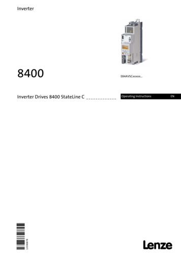
LubricationIf relubrication is carried out fromthe side, the housing cavities onthe side with the lubrication nipplemust be filled to approx. 100 %with grease so that the relubricationgrease can act immediately on thebearing. Depending on the sealselected and the application,the screw plug can be removedfrom points 4 and 3 or 3a of theupper section of the housing,and be replaced by the lubricationnipple included in the delivery(flat lubrication nipple toDIN 3404-M10X1 or taperedlubrication nipple toDIN 71412-AM10X1).If housings with DH seals are to berelubricated, the screw plug atpoint 6 must be removed in thelower section of the housing.The minimum relubricationquantities are indicated in theright-hand column of Table 5.If the grease outlet hole has beenopened or in case of a non-contactseal, the bearing cannot be overlubricated. If the temperature levelis higher at relubrication due tothe churning energy of the grease,this will return to its original levelafter a few hours’ running time,once the excess grease hasescaped. In the interests of theenvironment, controlled meteringof lubricant is recommended.6and MULTI2, are more suitable forrelubrication than greases of higherconsistency classes.3a3b30 30 65 41 2 3SNVIf the grease change intervalsfor particular applications are tooshort, relubrication is recommended.The lubricant can be introducedinto the housing from the side or,in the case of bearings witha lubrication slot and lubricationholes, through the centre.Due to their favourable flowbehaviour, greases of consistencyclass 2, e.g. Arcanol MULTITOP3a5 43b1 2SNVGrease relubrication,grease outlet hole3a3b4: Markings in the upper section of the housing for lubrication nipple connector holes
Lubrication5: Recommended grease quantitiesfor initial filling (housingcavities 60 %, bearing filledcompletely) and relubricationof housings SNVHousingGrease quantity -FSNV230-F9009501 2001 4001 0-F1 7002 0002 0002 5002 60090100120130140SNV290-FSNV300-FSNV320-FSNV340-F3 0003 1003 7004 500150160200240Automatic lubricatorsThe housings SNV can also bescrewed directly to the automaticlubricatorsFAG Motion Guard COMPACT,CHAMPION or CONCEPT6, see alsoWL 80 346, FAG Motion Guard –the intelligent lubricators.6: Automatic FAG lubricator Motion Guard CHAMPION7
LubricationGrease valvesOil lubricationFor operation at high speeds,e.g. in fan bearing arrangements,we can, by agreement, supplyFAG grease valves RSV, Figure 7.The grease valves for housingsSNV must be ordered separately.For bearings located by meansof adapter sleeves, grease valvesRSV5 or RSV6 should be used,for bearings with cylindrical bore,RSV2 or RSV3 should be used.FAG housings SNV are designedsuch that they are suitable forboth oil bath and recirculating oillubrication. The housings have alarge internal cavity with oil collectorpockets in the lower section aswell as connector facilities foroil inlet, oil outlet, oil levelsensors and temperature sensors.Mounting dimensions, Figure 8.When using oil bath lubrication,a minimum oil level (dimension h3in Figure 8) must be ensured.If the FAG double lip seal is used,a certain amount of oil leakage mustbe expected, which is unavoidablewith seals that are split and notspring-loaded. In order to limitoil leakage to a small quantity,the shaft in the double lip contactareas should be as follows:Hardness min. 55 HRC, ground freefrom spiral marks with R a 0,2 μmup to max. 0,5 μm.The parting line between the upperand lower sections of the housingmust be sealed with a thin layerof a commercial sealant(with permanent elasticity).In housings closed on one side,the base of the groove, into whichthe cover is inserted, must bebrushed with sealant.A technically oiltight version is onlypossible with a spring-loaded, unsplitrotary shaft seal. Please note thatthe housing must be ventilatedif oil bath lubrication is used(for example, the inlet hole can beclosed off using a ventilation plug).For design and availability,please contact our advisory service.7: FAG grease valves RSVGrease valveWidthbGrease otototo308313316322332810131516
LubricationHousing SNV for oil bath lubrication (suffix G944BA) included1 Oil level gauge OSGL.MOD24OMR-R./.,1 Ventilator VENT.MOD556E-R./., 2 Screw plugs VSB.DIN906-M10 1-ST.Version G944BA is available by agreement.n3Ventilatorn32ØD5M2h3M3g6M4g7Oil level gaugeαScrew plug8: Recommended dimensions of connector holes for oil inlet, oil outlet and oil level gaugewhen using oil bath lubrication. For recirculating oil lubrication, bore M 4 can be used for the oil outlet.HousingConnector for oil inletConnector for oil outletM2n 3/2mmM3α 35,528,5M10 1M10 1M10 1M10 G¼3840,542,545M10 1M10 1M10 1M10 0-FSNV340-FConnector for oil level �4345475028,540383930303030M10 1M10 1M10 1M10 5503636363658,5616065,5M10 1M10 1M10 1M10 536363636G¼G¼G¼G¼62,571,56876M10 1M10 1M10 1M10 55605836363636G¼G¼G¼737781M10 1M10 1M10 69
AssemblyMounting instructionsIf the bearings are located usingan adapter sleeve, the tight fitis achieved by axial pressing andradial expansion of the inner ring.The drive-up distance and reductionin radial internal clearance in thebearing (for recommended valuessee table, Figure 9) are a measureof this. FAG hydraulic nuts makeit easier to press the bearing ontothe shaft. The reduction in radialinternal clearance for sphericalroller bearings is determinedby measuring the residual airby means of feeler gauges.Self-aligning ball bearings aredriven up onto the sleeve,until a slight resistance can be feltupon deflection of the outer ring.However, the ring must be ableto rotate freely in a circumferentialdirection.Correct fitting has a decisiveinfluence on the achievablebearing life.For this reason, careful attentionmust be paid to the followingmounting instructions. For furtherinformation, see publicationWL 80 100, Mounting of rollingbearings.Bearings suitable for housings SNVcan be located on the shaft bymeans of adapter sleeves, or areseated directly on the shaft witha cylindrical bore. The necessarymachining tolerances for the shaftcan be found in Catalogue HR 1,Rolling Bearings.The upper and lower sections of thehousing are not interchangeable.Before fitting the plummer blockhousings SNV, carefully cleanthe mounting surface and checkits flatness.For flatness tolerances(DIN ISO 1101), see section“Load carrying capacity”, page 16.The clean lower section of thehousing is then located on themounting surface by means of thefixing screws. In order that thehousing can be aligned at a laterstage, the screws should not betightened using the full torque.The housing should be screwedinto place as required followingalignment.9: Reduction in radial internal clearance of FAG spherical roller bearings with tapered boreNominalbearing borediameterdRadial internal clearancebefore fittingInternal clearance groupCN ,110,131)Reduction inradial internalclearance 1)C4Control value for radialinternal clearanceafter fittingCNC3C4Displacementon taper 1:12 1)ShaftSleeveValid only for solid steel shafts and hollow shafts with a bore no larger than half the shaft diameter.Note: Bearings with a radial internal clearance value in the upper half of the tolerance range prior to fitting are mounted usingthe larger value for reduction in radial internal clearance or axial displacement, bearings in the lower half of the tolerance rangeare mounted using the smaller value for reduction in radial internal clearance or axial displacement.10
AssemblyMounting of bearings on the shaftBearings with cylindrical bore arepressed onto the shaft or preferablydriven up whilst warm. The bearinginner ring should rest correctlyagainst the shoulder on the shaft.If necessary, repress after coolingdown.When fitting bearings with taperedbore and adapter sleeves, it mustbe ensured that the bearing isin the centre of the housing beforelocating it. The shaft, completewith bearing, is inserted andaligned in the lower section of thehousing. The axial displacementof the bearing on the sleeve mustbe taken into consideration duringthis process.Mounting of split spherical rollerbearingsSplit FAG spherical roller bearingsshould be mounted by the samemethods. Special features for themounting of split bearings areindicated in the instructionsincluded with the delivery.11
AssemblyAssembly of SNV housings withdouble lip seals DH (Figure 10)1. Clean and check mountingsurface.2. Locate lower section of thehousing.3. Locate bearing on the shaft andfill up the free spaces in thebearing with some of the greasequantity, see Table 5.4. Fill the cavity between the seallips with grease. Insert one halfof the seal into each slot in thelower section of the housing.5. Insert shaft with bearing into thelower section of the housing.In the case of the locatingbearing, insert the two locatingrings. The non-locating bearingmust be in the centre of thehousing. In the case of housingsclosed on one side, insert onlyone seal and on the other sidethe cover DKV into the housingslot.6. Align lower section of the housingand tighten fixing screwsin the housing base with therecommended torque,see Table 13.7. Distribute the grease remainingafter lubrication of the bearing(point 3) evenly in the upper andlower sections of the housing.8. Insert the lubricated seal halvesinto the slots in the uppersection of the housing.9. Position the upper sectionof the housing and tightenthe connecting screws withthe recommended torque,see Table 13.10: Assembly of SNV housings with double lip seals DH12
AssemblyAssembly of SNV housingswith felt seals FSV (Figure 11)1. Clean and check mountingsurface.2. Locate lower section of thehousing.3. Insert round cord into slots inlower section of the housing.4. Introduce one half of adapterwith inserted, oil-impregnatedfelt strip to round cord in slotsin the lower section of thehousing.5. Locate bearing on the shaftand fill up the cavities in thebearing with some of thegrease quantity, see Table 5.6. Insert shaft with mountedbearing into lower section ofthe housing. In the case of thelocating bearing, insert the twolocating rings. The non-locatingbearing must be in the centreof the housing. In the caseof housings closed on one side,only one adapter with a feltstrip and, on the other side,the cover DKV is inserted intothe housing slot.7. Align lower section of housingand tighten fixing screws inhousing base with recommendedtorque, see Table 13.8. Distribute the grease remainingafter lubrication of the bearing(point 5) evenly in upper andlower sections of the housing.9. Insert round cord and adapterwith inserted and oil-impregnated felt strip into the slotsin the upper section of thehousing.10. Position upper section of thehousing and tighten connectingscrews with recommendedtorque, see Table 13.11: Assembly of SNV housings with felt seals FSV13
AssemblyAssembly of SNV housings withlabyrinth seals TSV (Figure 12)1. Clean and check mountingsurface.2. Locate lower section of thehousing.3. Push one labyrinth ring ontothe shaft. The slot in the ringbore must lie on the outside.4. Locate bearing on the shaft andfill up the cavities in thebearing with some of thegrease quantity, see Table 5.5. If necessary, push the secondlabyrinth ring onto the shaft(pay attention to position).In the case of housings closedon one side, insert the coverDKV into the housing slot.6. Fill up the labyrinth with grease.7. Insert shaft with mountedbearing and labyrinth ringsinto the lower section of thehousing. In the case of thelocating bearing, insert the twolocating rings. The non-locatingbearing must be in the centreof the housing.8. Align lower section of thehousing. Tighten fixing screwsin the housing base with therecommended torque,see Table 13.9. Round cord is pressed into theslot of the labyrinth ring borewhile rotating the shaft witha screwdriver. Then align thelabyrinth rings with the housingslots to provide even axial gaps.10. Distribute the grease remainingafter lubrication (point 4)evenly in the upper and lowersections of the housing.11. Position upper section of thehousing and tighten connectingscrews with recommendedtorque, see Table 13.1412: Assembly of SNV housings with labyrinth seals TSV
Additional holes for fixing screws and pinsAdditional holesfor fixing screws and pinss2SNVn2n1u2u1m1m2Additional holes for fixing screws and pinsHousingDesignationDimensions for pinsm1n1u1Dimensions for 24M24M30H/iH/iH/i1¼s2inchSNV housings are usually locatedusing two screws. The housing basehas two extended slots, so thatthe housings can be aligned duringassembly (dimensions m, u, vsee pages 20 ff.).For location on T profiles, fourscrews are required. Markingsindicate the locations (dimensionsm 2 and n 2 ) for boring additionalholes (diameter u 2 ) for the fixingscrews (s 2). Housings of the sizeSNV080 and above are availablewith these four additional holesfor fixing screws upon request.The ordering designation is asper the example:FAG plummer block housingSNV080-F-L-G944DA.Holes (diameter u 1 ) can bedrilled at marked locations(dimensions m 1 , n 1 ) for pinsto secure the position.15
Load carrying capacityLoad carrying capacityIn Table 13, page 17, the ruptureloads of the SNV housings madeof flake graphite cast iron (suffix L)are indicated as a function of theload direction.For spheroidal graphite cast iron(suffix D) a factor of 1,6 isapplicable.When determining the permissibleload, the usual safety factorsfor machine building must be takeninto consideration.The safety factors are:– 6 relative to the housing ruptureload– 3 relative to the maximum loadcarrying capacity of the connectingscrews and foot screws.The values are valid if the mountingsurface of the mating parts hasa flatness tolerance toDIN ISO 1101 of IT8(relative to distance a).A precondition for supporting loadsis that the housing base surface iscompletely and rigidly supported.For axial loading of the housings,C/d of the value for F 180 must beassumed. The permissible axialloading of the used bearings andthe axial retaining force of bearingson sleeves without the geometricallocking effect must be observed(see TI WL 80-14).16For load directions between 55 and 120 or in case of axial load,the housings are to be securedwith stops at the base in the lineof influence of the load, in casethe force parallel to the mountingsurface exceeds 0,05 · F 180 .The ring bolts in the upper sectionof the housing (from SNV215) mustnot be loaded to a value greaterthan the mass of the housingincluding the bearing.
Load carrying capacityF180 F150 F120 F90 A safety factor of 6 relative to the guide value for the housing rupture loadis recommended.F55 13: Load carrying capacityHousingHousing rupture loadConnecting screwsDesignationin the load directionThreadto DIN 13FAG55 kN90 120 150 180 Material 8.8Maximum load carryingcapacity of both screwswith contact betweenparting surfacesin load direction120 150 180 kNTighteningtorque **)Screwsfor housing base*)TighteningThread totorque **)DIN 13Material 8.8 Material 8.8 Material -F-L1 0001 0601 1801 1801 M307401 4501 4501 4501 450SNV290-F-LSNV300-F-LSNV320-F-LSNV340-F-L1 4001 5001 7001 9008509001 0001 03603603606402102102103701801801803207407407401 450M30M30M30M361 4501 4501 4502 600*)**)Screws for the housing base are not included in the FAG delivery.The tightening torques are maximum values with 90 % utilisation of the yield stress of the screw material and a friction factorof 0,14. We recommend tightening the screws to 70 % of these values.17
Ordering examplesOrdering examplesfor split FAG housings SNV,suitable FAG rollingbearings and accessoriesExample 1Plummer block housing(flake graphite cast iron),closed on one side,self-aligning ball bearing2210-K-TVH-C3 as locating bearing,location by means of adaptersleeve,double lip seal.Ordering:1 Plummer blockSNV090-F-Lhousing1 Self-aligning2210-K-TVH-C3ball bearing1 Adapter sleeveH3102 Locating ringsFRM90/91 CoverDKV0901 Double lip sealDH510Example 2Plummer block housing(flake graphite cast iron) forcontinuous shaft,split spherical roller bearing222SM70-TVPA as locating bearing,double lip seal.Ordering:1 Plummer blockSNV140-F-Lhousing1 Split spherical222SM70-TVPAroller bearing2 Locating ringsFRM140/12,52 Double lip seals DH516Example 4Plummer block housing(spheroidal graphite cast iron),closed on one side,spherical roller bearing23218-E1-TVPB as locating bearing,felt seal.Ordering:1 Plummer blockSNV160-F-Dhousing1 Spherical roller23218-E1-TVPBbearing1 Shaft nutKM181 Retaining plateMB181 CoverDKV1601 Felt sealFSV218Example 3Plummer block housing(flake graphite cast iron),closed on one side,spherical roller bearing 22216-E1-Kas locating bearing,location by means of adaptersleeve,labyrinth seal.Ordering:1 Plummer blockSNV140-F-Lhousing1 Spherical roller22216-E1-Kbearing1 Adapter sleeveH3161 Labyrinth ringTSV5161 CoverDKV140Designation example for housing SNV made from flake graphite cast iron:SNV100-F-LHousing material L Flake graphite cast ironD Spheroidal graphite cast ironThreaded holes for grease relubrication andgrease egressBearing outside diameter in mmDesignation of series SNV18
19
FAG plummer block housings, splitn4n3M10x1For bearings with cylindrical bore andfor bearings with tapered bore and adapter sleevemvg1Mh1SNVn 1 n2D3 mm5216546Shaftd1dmminch19,05D/e197040B/c15Bearings suitable for the housingUnsplit bearingsmmDesignation to 207536,544,542,755410,5Split sphericalroller 30v62052205K22205K220522205* The ordering designation which corresponds to the designation according to DIN can be found in Catalogue HR 1, Rolling Bearings.20
Bearings withtapered bore andadapter sleeveD5TSVd2TCVFSVDHDHVDKVdd1DKVTBearings IN 931M1DIN 580M5Mass kg1818831)–7627953211525Required accessoriesAdapterShaft Retaining Locating ringsleeve2 piecesnutplateDouble lipsealV ring V505X0
Features Split FAG housings of series SNV, Figure 1, are designed according to a modular concept and are a development of the SN/SNE houngsi s. Rolling bearings of various diameter