Transcription
Inverter840013390878Ä.H)oäInverter Drives 8400 StateLine CE84AVSCxxxxx.Operating InstructionsENL
Product keyProduct key:Nameplate:E84AVSCxxxxxxxxProduct range8400 Inverter DrivesGenerationA 1. generationTypeV vector-controlled inverterVersionSC StateLine CMounting typeE installationD Push-trough techniqueC cold-plate techniquePower e.g.251 25 x 101 W 0.25 kW222 22 x 102 W 2.2 kW Type designation Software versionVoltage class2 230/240 V, 1/N/PE AC (0.25 . 2.2 kW)4 400/500 V, 3/PE AC (0.37 . 45 kW)Ambient conditionsS standard industrial environment IE33 according to IEC 60721-3-3V rough environment (coated printed circuit boards)Safety systemX without safety technologyB with drive-based safety "safe torque off (STO)"The product key serves to identify delivered products by nameplate data.The product catalogue provides information on the possible configuration to order the products. Tip!Current instructions for the contents of the product CD and information and tools for the Lenze productsare provided in the internet:http://www.Lenze.com Download2Lenze · 8400 StateLine · Operating instructions · from Firmware V06.00 · DMS 1.2 EN · 12/2012 · TD05
Contents1About this documentation422.12.22.3Safety instructionsGeneral safety and application notes for Lenze controllersGeneral safety and application notes for Lenze motorsResidual hazards55783Overview of terminals94Connection/wiring of the controller1155.15.2Before commissioningSelection of the appropriate commissioning toolGeneral notes on parameters5.2.1Changing the parameterisation with the keypad5.2.2Change parameter settings with PC and Lenze software5.2.3Save parameter settings in the memory module safe against mains failure5.2.4User menu for quick access to frequently used parametersGeneral notes on applications5.3.1Select control modeFrequently used device commandsCheck software version (firmware ingDrive behaviour by default (Lenze setting)Quick commissioning with the keypadAdapting the most important parameters to the drive task6.3.1Basic settings6.3.2Application parameters6.3.3Motor control tics & troubleshootingLED status displays for device statusDiagnostics using the »EASY Starter«Diagnostic/Display parametersMonitoringError messagesMaloperation of the drive4444454647485388.18.2Adapting the application individuallyFunction block interconnection of the "Actuating drive speed" applicationActivating additional functions in the signal flow8.2.1Speed limit values8.2.2Speed blocking zones8.2.3Ramp smoothingImplementing more additional functions in the signal flow8.3.1Pre-assignment of the input and output interfaces8.3.2Motor potentiometer8.3.3Process controller8.3.4Parameter .3Lenze · 8400 StateLine · Operating instructions · from Firmware V06.00 · DMS 1.2 EN · 12/2012 · TD053
1About this documentation1About this documentationThis documentation applies to the 8400 StateLine C controller with the following nameplate data:Product rangeType designationfrom software version8400 StateLine CE84AVSCxxxxx06.00 The documentation contains important technical information on how to commission andoperate the 8400 StateLine C controller. The documentation applies to the "simple" "speed-controlled" operation preset by Lenze bydefault. The most important settings for commissioning will be explained so that manyapplications using the 8400 StateLine C controller and the preset application "actuating drivespeed" can be solved quickly. The documentation supplements the mounting instructions, the hardware manual and thereference manual for the 8400 StateLine C controller. The hardware and reference manual are included in the scope of supply. in electronic format.Definition of the notes usedThe following signal words and symbols are used in this documentation to indicate dangers andimportant information:SymbolSignal wordMeaning Danger!Danger of personal injury through dangerous electrical voltageReference to an imminent danger that may result in death or serious personal injuryif the corresponding measures are not taken. Danger!Danger of personal injury through a general source of dangerReference to an imminent danger that may result in death or serious personal injuryif the corresponding measures are not taken. Stop!Danger of property damageReference to a possible danger that may result in property damage if thecorresponding measures are not taken.Note!Important note to ensure trouble-free operation 4Lenze · 8400 StateLine · Operating instructions · from Firmware V06.00 · DMS 1.2 EN · 12/2012 · TD05
2Safety instructions2.1General safety and application notes for Lenze controllers2 Safety instructionsDanger!Sticker with warning note must be displayed prominently and close to the device!Description of the warning signs 2.1 Long discharge time!All power terminals remain live for some minutes after mains disconnection!The time is given below the warning symbol on the device. High leakage current!Carry out fixed installation and PE connection in accordance with EN 61800-5-1! Electrostatic sensitive devices!Before working on the device, the staff must ensure to be free of electrostatic charge! Hot surface!Risk of burns!Hot surfaces should not be touched without wearing protective gloves.General safety and application notes for Lenze controllers(according to Low-Voltage Directive 2006/95/EG)For your personal safetyDisregarding the following safety measures can lead to severeinjury to persons and damage to material assets: Only use the product as directed. Never commission the product in the event of visible damage. Never commission the product before assembly has beencompleted. Do not carry out any technical changes on the product. Only use the accessories approved for the product. Only use original spare parts from Lenze. Observe all regulations for the prevention of accidents,directives and laws applicable on site. Transport, installation, commissioning and maintenancework must only be carried out by qualified personnel.– Observe IEC 364 and CENELEC HD 384 or DIN VDE 0100 andIEC report 664 or DIN VDE 0110 and all national regulationsfor the prevention of accidents.– According to this basic safety information, qualified, skilledpersonnel are persons who are familiar with the assembly,installation, commissioning, and operation of the productand who have the qualifications necessary for theiroccupation. Observe all specifications in this documentation.– This is the condition for safe and trouble-free operation andthe achievement of the specified product features.– The procedural notes and circuit details described in thisdocumentation are only proposals. It's up to the user tocheck whether they can be transferred to the particularapplications. Lenze Drives GmbH does not accept anyliability for the suitability of the procedures and circuitproposals described. Depending on their degree of protection, some parts of theLenze controllers (frequency inverters, servo inverters, DCspeed controllers) and their accessory components can belive, moving and rotating during operation. Surfaces can behot.– Non-authorised removal of the required cover,inappropriate use, incorrect installation or operation,creates the risk of severe injury to persons or damage tomaterial assets.– For more information, please see the documentation. High amounts of energy are produced in the controller.Therefore it is required to wear personal protectiveequipment (body protection, headgear, eye protection, earprotection, hand guard).Lenze · 8400 StateLine · Operating instructions · from Firmware V06.00 · DMS 1.2 EN · 12/2012 · TD055
2Safety instructions2.1General safety and application notes for Lenze controllersApplication as directedControllers are components which are designed for installationin electrical systems or machines. They are not to be used asdomestic appliances, but only for industrial purposes accordingto EN 61000-3-2.When controllers are installed into machines, commissioning(i.e. starting of the operation as directed) is prohibited until it isproven that the machine complies with the regulations of the ECDirective 2006/42/EC (Machinery Directive); EN 60204 must beobserved.Commissioning (i.e. starting of the operation as directed) is onlyallowed when there is compliance with the EMC Directive(2004/108/EC).The controllers meet the requirements of the Low-VoltageDirective 2006/95/EC. The harmonised standard EN 61800-5-1applies to the controllers.The technical data and supply conditions can be obtained fromthe nameplate and the documentation. They must be strictlyobserved.Warning: Controllers are products which can be installed in drivesystems of category C2 according to EN 61800-3. These productscan cause radio interferences in residential areas. In this case,special measures can be necessary.(RCD), other protective measures can be taken as well, e.g.electrical isolation by double or reinforced insulation or isolationfrom the supply system by means of a transformer.Transport, storagePlease observe the notes on transport, storage, and appropriatehandling. Observe the climatic conditions according to thetechnical data.Maintenance and servicingThe controllers do not require any maintenance if the prescribedoperating conditions are observed.InstallationThe controllers must be installed and cooled according to theinstructions given in the corresponding documentation.The ambient air must not exceed degree of pollution 2 accordingto EN 61800-5-1.Ensure proper handling and avoid excessive mechanical stress.Do not bend any components and do not change any insulationdistances during transport or handling. Do not touch anyelectronic components and contacts.Controllers contain electrostatic sensitive devices which caneasily be damaged by inappropriate handling. Do not damage ordestroy any electrical components since this might endangeryour health!OperationIf necessary, systems including controllers must be equippedwith additional monitoring and protection devices according tothe valid safety regulations (e.g. law on technical equipment,regulations for the prevention of accidents). The controllers canbe adapted to your application. Please observe thecorresponding information given in the documentation.After the controller has been disconnected from the supplyvoltage, all live components and power terminals must not betouched immediately because capacitors can still be charged.Please observe the corresponding stickers on the controller.All protection covers and doors must be shut during operation.Notes for UL-approved systems with integrated controllers:UL warnings are notes that only apply to UL systems. Thedocumentation contains special UL notes.Certain controller versions support safety functions (e.g. "Safetorque off", formerly "Safe standstill") according to therequirements of the EC Directive 2006/42/EC. The notes on theintegrated safety system provided in this documentation mustbe observed.DisposalRecycle metal and plastic materials. Ensure professional disposalof assembled PCBs.The product-specific safety and application notes given in theseinstructions must be observed!Electrical connectionWhen working on live controllers, observe the applicablenational regulations for the prevention of accidents (e.g. VBG 4).The electrical installation must be carried out according to theappropriate regulations (e.g. cable cross-sections, fuses, PEconnection). Additional information can be obtained from thedocumentation.This documentation contains information on installation incompliance with EMC (shielding, earthing, filter, and cables).These notes must also be observed for CE-marked controllers.The manufacturer of the system is responsible for compliancewith the limit values demanded by EMC legislation. Thecontrollers must be installed in housings (e.g. control cabinets) tomeet the limit values for radio interferences valid at the site ofinstallation. The housings must enable an EMC-compliantinstallation. Observe in particular that e.g. the control cabinetdoors have a circumferential metal connection to the housing.Reduce housing openings and cutouts to a minimum.Lenze controllers may cause a DC current in the PE conductor. Ifa residual current device (RCD) is used for protection againstdirect or indirect contact for a controller with three-phasesupply, only a residual current device (RCD) of type B ispermissible on the supply side of the controller. If the controllerhas a single-phase supply, a residual current device (RCD) of typeA is also permissible. Apart from using a residual current device6Lenze · 8400 StateLine · Operating instructions · from Firmware V06.00 · DMS 1.2 EN · 12/2012 · TD05
2Safety instructions2.2General safety and application notes for Lenze motors2.2General safety and application notes for Lenze motors(according to Low-Voltage Directive 2006/95/EG)GeneralLowvoltage machines have hazardous live and rotating parts andpossibly also hot surfaces.Synchronous machines induce voltages at open terminals onnections,commissioning and maintenance must be carried out byqualified, skilled personnel (EN 501101 (VDE 0105100) and IEC60364 must be observed). Inappropriate use creates the risk ofsevere injury to persons and damage to material assets.Lowvoltage machines may only be operated under theconditions that are indicated in the section "Application asdirected".The conditions at the place of installation must comply with thedata given on the nameplate and in the documentation.Application as directedLowvoltage machines are intended for commercial installations.They comply with the harmonised standards of the seriesEN 60034 (VDE 0530). Their use in potentially explosiveatmospheres is prohibited unless they are expressly intended forsuch use (follow additional instructions).Lowvoltage machines are components for installation intomachines as defined in the Machinery Directive 2006/42/EC.Commissioning is prohibited until the conformity of the endproduct with this directive has been established (follow i. a. EN602041).Lowvoltage machines with IP23 protection or less are onlyintended for outdoor use when applying special protectivefeatures.The integrated brakes must not be used as safety brakes. Itcannot be ruled out that factors which cannot be influenced,such as oil ingress due to a defective Aside shaft seal, cause abrake torque reduction.Transport, storageDamages must be reported immediately upon receipt to theforwarder; if required, commissioning must be excluded.Tighten screwedin ring bolts before transport. They are designedfor the weight of the lowvoltage machines, do not apply extraloads. If necessary, use suitable and adequately dimensionedmeans of transport (e. g. rope guides).Remove transport locking devices before commissioning. Reusethem for further transport. When storing lowvoltage machines,ensure a dry, dustfree and lowvibration (veff 0.2 mm/s)environment (bearing damage while being stored).InstallationEnsure an even surface, solid foot/flange mounting and exactalignment if a direct clutch is connected. Avoid resonances withthe rotational frequency and double mains frequency which maybe caused by the assembly. Turn rotor by hand, listen for unusualslipping noises. Check the direction of rotation when the clutchis not active (observe section "Electrical connection").Use appropriate means to mount or remove belt pulleys andclutches (heating) and cover them with a touch guard. Avoidimpermissible belt tensions.The machines are half-key balanced. The clutch must be half-keybalanced, too. This visible jutting out part of the key must beremoved.If required, provide pipe connections.Designs with shaft end at bottom must be protected with a coverwhich prevents the ingress of foreign particles into the fan. Freecirculation of the cooling air must be ensured. The exhaust air als the exhaust air of other machines next to the drive system must not be taken in immediately.Electrical connectionAll operations must only be carried out by qualified and skilledpersonnel on the low-voltage machine at standstill anddeenergised and provided with a safe guard to prevent anunintentional restart.This also applies to auxiliary circuits (e. g.brake, encoder, blower).Check safe isolation from supply!If the tolerances specified in EN 60034-1; IEC 34 (VDE 0530-1) voltage 5 %, frequency 2 %, waveform, symmetry - areexceeded, more heat will be generated and the electromagneticcompatibility will be affected.Observe the data on the nameplate, operating notes, and theconnection diagram in the terminal box.The connection must ensure a continuous and safe electricalsupply (no loose wire ends); use appropriate cable terminals. Theconnection to the PE conductor must be safe. The plug-inconnectors must be bolt tightly (to stop).The clearances between blank, live parts and to earth must notfall below 8 mm at Vr 550 V, 10 mm at Vr 725 V, 14 mm atVr 1000 V.The terminal box must be free of foreign particles, dirt andmoisture. All unused cable entries and the box itself must besealed against dust and water.Commissioning and operationBefore commissioning after longer storage periods, measureinsulation resistance. In case of values 1 kΩ per volt of ratedvoltage, dry winding.For trial run without output elements, lock the featherkey. Donot deactivate the protective devices, not even in a trial run.Check the correct operation of the brake before commissioninglow-voltage machines with brakes.Integrated thermal detectors do not provide full protection forthe machine. If necessary, limit the maximum current.Parameterise the controller so that the motor will be switchedoff with I Ir after a few seconds of operation, especially at therisk of blocking.Vibrational severities veff 3.5 mm/s (PN 15 kW) or 4.5 mm/s(PN 15 kW) are acceptable if the clutch is activated.If deviations from normal operation occur, e.g. increasedtemperatures, noises, vibrations, find the cause and, if required,contact the manufacturer. In case of doubt, switch off the lowvoltage machine.If the machine is exposed to dirt, clean the air paths regularly.Shaft sealing rings and roller bearings have a limited service life.Regrease bearings with relubricating devices while the lowvoltage machine is running. Only use the grease recommendedby the manufacturer. If the grease drain holes are sealed with aplug, (IP54 drive end; IP23 drive and non-drive end), remove plugbefore commissioning. Seal bore holes with grease. Replaceprelubricated bearings (2Z bearing) after approx. 10,000 h 20,000 h, at the latest however after 3 - 4 years.The product-specific safety and application notes given in theseinstructions must be observed!Lenze · 8400 StateLine · Operating instructions · from Firmware V06.00 · DMS 1.2 EN · 12/2012 · TD057
2Safety instructions2.3Residual hazards2.3Residual hazardsProtection of personsBefore working on the controller, check if no voltage is applied tothe power terminals because - depending on the device - the power terminals U, V, W, UG,- UG, Rb1 and Rb2 remain live for at least 3 . 20 minutes afterdisconnecting the mains. the power terminals L1, L2, L3; U, V, W, UG, - UG, Rb1 andRb2 remain live when the motor is stopped.Device protectionConnect/disconnect all pluggable terminals only in deenergisedcondition!Detach the controller from the installation, e.g. from the rearpanel of the control cabinet, only in deenergised condition!Motor protectionWith some settings of the controller, the connected motor can beoverheated. E.g. longer operation of the DC injection brake. Longer operation of self-ventilated motors at low speed.8Protection of the machine/plantDrives can reach dangerous overspeeds (e. g. setting of highoutput frequencies in connection with motors and machines notsuitable for this purpose)! The drive controllers do not provideprotection against such operating conditions. For this purpose,use additional components.Switch contactors in the motor cable only if the controller isinhibited. When switching contactors in the motor cable whilethe controller is enabled, you can activate monitoring functionsof the controller. If no monitoring function is activated,switching is permissible.Parameter set transferDuring the parameter set transfer, control terminals of thecontrollers can adopt undefined states! Therefore it is requiredto disable the terminal X4 (digital input signals) before thetransfer starts. This ensures that the controller is inhibited andall control terminals have the firmly defined ”LOW” status.Lenze · 8400 StateLine · Operating instructions · from Firmware V06.00 · DMS 1.2 EN · 12/2012 · TD05
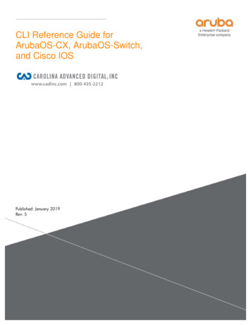
3Overview of terminals3Overview of terminalsPower terminalsPower range 0.25 . 3 kWPower range 3 . 22 kW(Device sizes 1 . 3)(Device sizes 4 . 6)Power range 30 . 45 kW(Device size 7)X80 Terminal strip for drive-based safety "safe torqueoff (STO)" (option)X100 Mains/DC-bus voltage for 400 V devicesX101 Relay output AC 250 V, 3 A DC 24V, 2A DC 240 V, 0.16 AX105 Motor/external brake resistorX106 Motor temperature monitoringIT Contact screws for interference suppression (onthe supply side and on the on the motor side) Before using the controller in the IT system,loose both contact screws. Please observe the notes in the hardwaremanual and in mounting instructions of thecontroller and filters.MCI Slot for communication module MCI abbreviation for "ModuleCommunication Interface" Sticker with warningLenze · 8400 StateLine · Operating instructions · from Firmware V06.00 · DMS 1.2 EN · 12/2012 · TD059
3Overview of terminalsControl terminalsX1 CANopen connectionS1 CANopen settings(Bus terminating resistor, baud rate and nodeaddress)X3X4 Analog inputs/outputs 10 V reference voltageNote: Voltage input A1U and current input A1Imust not be used simultaneously! Digital inputs/outputs(according to IEC 61131-2, type 1) External 24 V supply voltage(for control electronics) 24 V voltage outputX6 Diagnostic interface (DIAG) For keypad ( 14) or PC connection ( 18)MMI Slot for memory module ( 19) MMI abbreviation for "Memory ModuleInterface"LED Status displays of the device status ( 44)& 1 581& 1 (55'59 5' '59 (55Description of the warning signs 10 Long discharge time!All power terminals remain live for some minutes after mains disconnection!The time is given below the warning symbol on the device. High leakage current!Carry out fixed installation and PE connection in accordance with EN 61800-5-1! Electrostatic sensitive devices!Before working on the device, the staff must ensure to be free of electrostatic charge! Hot surface!Risk of burns!Hot surfaces should not be touched without wearing protective gloves.Lenze · 8400 StateLine · Operating instructions · from Firmware V06.00 · DMS 1.2 EN · 12/2012 · TD05
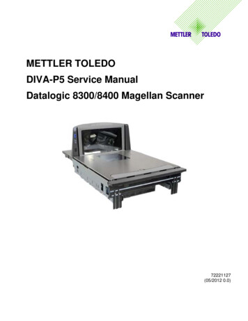
4Connection/wiring of the controller4Connection/wiring of the controller1/N/PE AC 230 V3/PE AC 400 V/500 VL1NPEL1L2L3NPE F1KF2F1 F3KF4ZZOKOIPEKL1 NIL1 L2 L3 UG -UGPEX100JRX100JRbbE84AVSCxxxx2.KX105Rb1 Rb2 UWPE"Rb1 Rb2 UT1 T2 Rb1 Rb2Rb""M3 WPE" PTC"M3 "T1 T2 RbJ X106V "Rb1 Rb2""J M3 PTCM3 Wiring of the power and motor terminals of 230V devices (on the left) and 400V devices (on the right)X3 - Analog terminals( 96&[[[[[ 9 P *1' 9*1' ,2[4-2]X105X106V "[4-1]E84AVSCxxxx4.K 5 8 ,* 2 8 ( ,5)5', ', ', ', '2 *,2; N 9A1U Main speed setpoint10 V 100 % reference speed 1500 rpm(applies to 4-pole asynchronous motors)O1U Actual speed value10 V 100 % reference speed 1500 rpm; ; &201&12X4 - Digital terminals 9 '&24E External supply - control electronics (optional)RFR Controller enable / Reset of error messageDI1 Fixed speed setpoint 1 (40 % of the reference speed)DI2 Fixed speed setpoint 2 (60 % of the reference speed)DI3 Manual DC-injection brakingDI4 Change of direction of rotationDO1 Status "Drive is ready"X101 - relay outputCOM/NO Status "Error is pending"Wiring of the control terminals / preconfigured assignment (Lenze setting)Lenze · 8400 StateLine · Operating instructions · from Firmware V06.00 · DMS 1.2 EN · 12/2012 · TD0511
5Before commissioning5.1Selection of the appropriate commissioning tool5Before commissioningBeing a component of a machine which includes a speed-variable drive system, the controller needsto be adjusted to its drive task. The controller is adjusted by changing parameters which are savedin the memory module. The parameters can be accessed by keypad, by the »EASY Starter« or by the»Engineer«. Access is also possible by a master control via fieldbus communication, e.g. via CAN bus. Danger!In general, changing a parameter causes an immediate response in the controller!This may lead to undesirable behaviour on the motor shaft if the controller has beenenabled! Setpoint sources, for instance, may switch over all of a sudden (e.g. whenconfiguring the signal source for the main setpoint).Certain device commands or settings which may cause critical states of drive behaviourconstitute exceptions. Such parameter changes are only possible if the controller isinhibited. Otherwise, a corresponding error message will be issued.5.1Selection of the appropriate commissioning toolThere are several possibilities for commissioning the 8400 StateLine controller:Commissioning with keypad X400 (diagnosis terminal X400)The keypad is an alternative to the PC for the local operation, parameterisation, and diagnostics ina simple manner. The keypad is especially suitable for test or demonstration purposes and if only afew parameters have to be adapted.Commissioning with PC and »EASY Starter«The »EASY Starter« is a Lenze tool for easy online diagnostics, parameter setting andcommissioning of the controller.Commissioning with PC and »Engineer«The »Engineer« is a Lenze engineering software for parameter setting across all devices,configuring and diagnosing individual components (as for instance controllers, industrial PCs,motors, I/O systems) and machine control systems.12Lenze · 8400 StateLine · Operating instructions · from Firmware V06.00 · DMS 1.2 EN · 12/2012 · TD05
5Before commissioning5.1Selection of the appropriate commissioning tool Tip!The Engineering tools »EASY Starter« and »Engineer StateLevel« are provided free of chargein the internet:http://www.Lenze.com Download Software downloadsFor communication between PC and controller, the USB diagnostic adapter can be used forinstance (see the following accessories overview).Accessories for commissioningVersionFeaturesProduct keyKeypad X400EZAEBK1001 Menu navigation Backlighted graphic display for comfortably representinginformation 4 navigation keys, 2 context-sensitive keys Adjustable RUN/STOP function Hot-plug capable Can be used for L-force Inverter Drives 8400 and ServoDrives 9400Diagnosis terminal X400EZAEBK2001 Keypad X400 in a robust housing Also suitable for installation into the control cabinet door incl. 2.5 m cable Enclosure IP20, in case of front installation in controlcabinet IP65USB diagnostic adapterE94AZCUS Input-side voltage supply via USB connection from PC Output-side voltage supply via the diagnostic interface ofthe controller Diagnostic LED Electrical isolation of PC and controller Hot-plug capableConnecting cable forUSB diagnostic adapter2.5 m length EWL00705 m length EWL007110 m length EWL0072Lenze · 8400 StateLine · Operating instructions · from Firmware V06.00 · DMS 1.2 EN · 12/2012 · TD0513
5Before commissioning5.2General notes on parameters5.2General notes on parametersAll parameters for controller parameterising or monitoring are saved as so-called "codes". The codes are numbered and indicated by the prefix "C" before the code, e.g. "C00002". Moreover, each code has a name and specific attributes, as for example access type (reading,writing), data type, limit values and default setting ("Lenze setting"). For the sake of clarity, some codes contain "subcodes" for saving parameters. This Manual usesa slash "/" as a separator between code and subcode, e.g. C00118/3". According to their functionality, the parameters are divided into three groups: Setting parameters: For specifying setpoints and for setting device / monitoring functions. Configuration parameters: For configuring signal connections and terminal assignments. Diagnostic/display parameters: For displaying device-internal process factors, current actualvalues and status messages.5.2.1Changing the parameterisation with the keypadThe keypad is simply plugged on the diagnosticinterface X6 ("DIAG") at the front of the standarddevice.Plugging and unplugging the keypad is possibleduring operation.Keypad display and control elements/&' GLVSOD\ HDGOLQH7ULSOH OLQH GLVSOD\'HYLFH VWDWH&XUUHQW IXQFWLRQ OHIW IXQFWLRQ NH\,Q PDQXDO FRQWURO PRGH6WRS PRWRU14&XUUHQW IXQFWLRQ ULJKW IXQFWLRQ NH\WXSTVYR,Q PDQXDO FRQWURO PRGH6WDUW PRWRULenze · 8400 StateLine · Operating instructions · from Firmware V06.00 · DMS 1.2 EN · 12/2012 · TD05
5Before commissioning5.2General notes on parametersLCD displayHeadlineIn the menu level: Menu nameIn the parameter level: Parameter nameThree-part displayIn the menu level: List of available menusIn the parameter level: Code/subcode and setting or actual valueDevice status Controller is switched on Pulse inhibit is active Change parameter setting(change to editing mode) Back to main menu Accept change in the controller(no saving with mains failure protection ) Controller is enabledController is inhibitedQuick stop is activeCurrent limit exceededSpeed controller 1 in the limitationFunction - left function keySystem fault is active"Fault" device status is activeDevice status "Trouble" activeDevice status "TroubleQSP" activeA warning is indicatedFunction - right function keyAbort (discard change)Parame
controllers must be installed in housings (e.g. control cabinets) to meet the limit values for radio interferences valid at the site of installation. The housings must enable an EMC-compliant installation. Observe in particular that e.g. the control cabinet doors have a circumferential metal connection to the housing.