Transcription
VX 520Installation GuideVeriFone Part Number DOC252-003-EN-B, Revision B
VX 520 Installation Guide 2010 VeriFone, Inc.All rights reserved. No part of the contents of this document may be reproduced or transmitted in any form without the writtenpermission of VeriFone, Inc.The information contained in this document is subject to change without notice. Although VeriFone has attempted to ensure theaccuracy of the contents of this document, this document may include errors or omissions. The examples and sample programs arefor illustration only and may not be suited for your purpose. You should verify the applicability of any example or sample programbefore placing the software into productive use. This document, including without limitation the examples and software programs, issupplied “As-Is.”VeriFone, the VeriFone logo, Omni, VeriCentre, Verix, and ZonTalk are registered trademarks of VeriFone. Other brand names ortrademarks associated with VeriFone’s products and services are trademarks of VeriFone, Inc.All other brand names and trademarks appearing in this manual are the property of their respective holders.Comments? Please e-mail all comments on this document to your local VeriFone Support Team.VeriFone, Inc.2099 Gateway Place, Suite 600San Jose, CA, 95110 USAwww.verifone.comVeriFone Part Number DOC252-003-EN-B, Revision B
CONTENTSP R EF AC E . . . . . . . . . . . . . . . . . . . . . . . . . . . . . . . . . . . . . . . 5Audience. . . . . . . . . . . . . . . . . . . . . . . . . . . . . . . . . . . . . . . . . . . . . . . . . . . . . . . .Organization . . . . . . . . . . . . . . . . . . . . . . . . . . . . . . . . . . . . . . . . . . . . . . . . . . . . .Related Documentation . . . . . . . . . . . . . . . . . . . . . . . . . . . . . . . . . . . . . . . . . . . .Conventions and Acronyms . . . . . . . . . . . . . . . . . . . . . . . . . . . . . . . . . . . . . . . . .Document Conventions. . . . . . . . . . . . . . . . . . . . . . . . . . . . . . . . . . . . . . . . . .Acronym Definitions . . . . . . . . . . . . . . . . . . . . . . . . . . . . . . . . . . . . . . . . . . . .555666C HA P TE R 1Terminal Overview VX 520 Terminal. . . . . . . . . . . . . . . . . . . . . . . . . . . . . . . . . . . . . . . . . . . . . . . . . 10VX 520 Features and Benefits . . . . . . . . . . . . . . . . . . . . . . . . . . . . . . . . . . . 10VX 520 Sprocket Terminal . . . . . . . . . . . . . . . . . . . . . . . . . . . . . . . . . . . . . . . . . 13VX 520 Sprocket Features and Benefits. . . . . . . . . . . . . . . . . . . . . . . . . . . . 13C HA P TE R 2Terminal Setup VX 520 Setup . . . . . . . . . . . . . . . . . . . . . . . . . . . . . . . . . . . . . . . . . . . . . . . . . . . 16Selecting Terminal Location . . . . . . . . . . . . . . . . . . . . . . . . . . . . . . . . . . . . .Unpacking the Shipping Carton . . . . . . . . . . . . . . . . . . . . . . . . . . . . . . . . . .Examining Terminal Features . . . . . . . . . . . . . . . . . . . . . . . . . . . . . . . . . . . .Establishing Telephone Line Connections . . . . . . . . . . . . . . . . . . . . . . . . . .Installing a Paper Roll in the Printer . . . . . . . . . . . . . . . . . . . . . . . . . . . . . . .Installing/Replacing MSAM Cards . . . . . . . . . . . . . . . . . . . . . . . . . . . . . . . .Connecting Optional Devices . . . . . . . . . . . . . . . . . . . . . . . . . . . . . . . . . . . .Connecting the Terminal Power Pack. . . . . . . . . . . . . . . . . . . . . . . . . . . . . .Privacy Shield (Optional) . . . . . . . . . . . . . . . . . . . . . . . . . . . . . . . . . . . . . . .Using the Smart Card Reader. . . . . . . . . . . . . . . . . . . . . . . . . . . . . . . . . . . .Using the Magnetic Card Reader . . . . . . . . . . . . . . . . . . . . . . . . . . . . . . . . .VX 520 Sprocket Setup . . . . . . . . . . . . . . . . . . . . . . . . . . . . . . . . . . . . . . . . . . .Selecting Terminal Location . . . . . . . . . . . . . . . . . . . . . . . . . . . . . . . . . . . . .Unpacking the Shipping Carton . . . . . . . . . . . . . . . . . . . . . . . . . . . . . . . . . .Examining Terminal Features . . . . . . . . . . . . . . . . . . . . . . . . . . . . . . . . . . . .Establishing Telephone and Line Connections. . . . . . . . . . . . . . . . . . . . . . .Installing Paper Tray . . . . . . . . . . . . . . . . . . . . . . . . . . . . . . . . . . . . . . . . . . .Installing Paper in the Tray . . . . . . . . . . . . . . . . . . . . . . . . . . . . . . . . . . . . . .Installing/Replacing MSAM Cards . . . . . . . . . . . . . . . . . . . . . . . . . . . . . . . .Connecting Optional Devices . . . . . . . . . . . . . . . . . . . . . . . . . . . . . . . . . . . .Connecting the Terminal Power Pack. . . . . . . . . . . . . . . . . . . . . . . . . . . . . .Privacy Shield (Optional) . . . . . . . . . . . . . . . . . . . . . . . . . . . . . . . . . . . . . . .Using the Smart Card Reader. . . . . . . . . . . . . . . . . . . . . . . . . . . . . . . . . . . .Using the Magnetic Card Reader . . . . . . . . . . . . . . . . . . . . . . . . . . . . . . . . X 520 INSTALLATION GUIDE3
C ONTENTSC H AP T ER 3Specifications VX 520 Specifications. . . . . . . . . . . . . . . . . . . . . . . . . . . . . . . . . . . . . . . . . . . . . 48Power . . . . . . . . . . . . . . . . . . . . . . . . . . . . . . . . . . . . . . . . . . . . . . . . . . . . . .DC Power Pack. . . . . . . . . . . . . . . . . . . . . . . . . . . . . . . . . . . . . . . . . . . . . . .Temperature . . . . . . . . . . . . . . . . . . . . . . . . . . . . . . . . . . . . . . . . . . . . . . . . .External Dimensions . . . . . . . . . . . . . . . . . . . . . . . . . . . . . . . . . . . . . . . . . . .VX 520 Sprocket Specifications . . . . . . . . . . . . . . . . . . . . . . . . . . . . . . . . . . . . .Power . . . . . . . . . . . . . . . . . . . . . . . . . . . . . . . . . . . . . . . . . . . . . . . . . . . . . .DC Power Pack. . . . . . . . . . . . . . . . . . . . . . . . . . . . . . . . . . . . . . . . . . . . . . .Temperature . . . . . . . . . . . . . . . . . . . . . . . . . . . . . . . . . . . . . . . . . . . . . . . . .External Dimensions . . . . . . . . . . . . . . . . . . . . . . . . . . . . . . . . . . . . . . . . . . .484848484949494949C H AP T ER 4Maintenance Clean the Terminal . . . . . . . . . . . . . . . . . . . . . . . . . . . . . . . . . . . . . . . . . . . . . . . 51Terminal Contacts . . . . . . . . . . . . . . . . . . . . . . . . . . . . . . . . . . . . . . . . . . . . . . . 51Smart Card Reader . . . . . . . . . . . . . . . . . . . . . . . . . . . . . . . . . . . . . . . . . . . . . . 51C H AP T ER 5VeriFone Service Return a Terminal for Service. . . . . . . . . . . . . . . . . . . . . . . . . . . . . . . . . . . . . . . 53and Support Accessories and Documentation . . . . . . . . . . . . . . . . . . . . . . . . . . . . . . . . . . . . 54Power Pack. . . . . . . . . . . . . . . . . . . . . . . . . . . . . . . . . . . . . . . . . . . . . . . . . .Printer Paper. . . . . . . . . . . . . . . . . . . . . . . . . . . . . . . . . . . . . . . . . . . . . . . . .Supplementary Hardware . . . . . . . . . . . . . . . . . . . . . . . . . . . . . . . . . . . . . . .VeriFone Cleaning Kit . . . . . . . . . . . . . . . . . . . . . . . . . . . . . . . . . . . . . . . . . .Telephone Line Cord . . . . . . . . . . . . . . . . . . . . . . . . . . . . . . . . . . . . . . . . . .Documentation . . . . . . . . . . . . . . . . . . . . . . . . . . . . . . . . . . . . . . . . . . . . . . .545454555555C H AP T ER 6Troubleshooting Blank Display . . . . . . . . . . . . . . . . . . . . . . . . . . . . . . . . . . . . . . . . . . . . . . . . . . . 57Guidelines Terminal Does Not Dial Out . . . . . . . . . . . . . . . . . . . . . . . . . . . . . . . . . . . . . . . . 58Printer Paper Jam. . . . . . . . . . . . . . . . . . . . . . . . . . . . . . . . . . . . . . . . . . . . . . . .Keypad Does Not Respond . . . . . . . . . . . . . . . . . . . . . . . . . . . . . . . . . . . . . . . .Peripheral Device Does Not Work . . . . . . . . . . . . . . . . . . . . . . . . . . . . . . . . . . .Transactions Fail To Process . . . . . . . . . . . . . . . . . . . . . . . . . . . . . . . . . . . . . . .Printer Does Not Print. . . . . . . . . . . . . . . . . . . . . . . . . . . . . . . . . . . . . . . . . . . . .Terminal Display Does not Show Correct or Readable Information . . . . . . . . . .Terminal Does Not Start . . . . . . . . . . . . . . . . . . . . . . . . . . . . . . . . . . . . . . . . . . .58585859606060I N DE X . . . . . . . . . . . . . . . . . . . . . . . . . . . . . . . . . . . . . . . . . 614VX 520 INSTALLATION GUIDE
PREFACEThis guide is your primary source of information for setting up and installing theVX 520 terminal.AudienceOrganizationThis guide is useful for anyone installing and configuring a VX 520 terminal. Thismanual also provides a basic description of the terminal features.This guide is organized as follows:Chapter 1, Terminal Overview. Provides an overview of the VX 520 terminals.Chapter 2, Terminal Setup. Explains how to set up and install the VX 520terminals. It tells you how to select a location, establish power and telephone lineconnections, and how to configure optional peripheral devices.Chapter 3, Specifications. Discusses power requirements and dimensions of theVX 520 terminals.Chapter 4, Maintenance. Explains how to maintain your VX 520 terminals.Chapter 5, VeriFone Service and Support. Provides information on contactingyour local VeriFone representative or service provider, and information on how toorder accessories or documentation from VeriFone.Chapter 6, Troubleshooting Guidelines. Provides troubleshooting guidelines,should you encounter a problem in terminal installation and configuration.RelatedDocumentationTo learn more about the VX 520 terminal, refer to the following set of documents:VX 520 Certifications and RegulationsVPN DOC252-001-ENVX 520 Quick Installation GuideVPN DOC252-002-ENVX 520 Reference ManualVPN DOC252-004-ENVX 520 Sprocket Printer Certifications and RegulationsVPN DOC252-006-ENVX 520 Sprocket Printer Quick Installation GuideVPN DOC252-007-ENVX 520 INSTALLATION GUIDE5
P REFACEConventions and AcronymsConventions andAcronymsThis section describes the conventions and acronyms used in this guide.Document Various conventions are used to help you quickly identify special formatting.Conventions Table 1 describes these conventions and provides examples of their use.Table 1Document ConventionsConventionBlueText in blue indicates termsthat are cross-referenced.See Conventions and Acronyms.ItalicsItalic typeface indicatesbook titles or emphasis.You must install a roll of thermalsensitive paper in the printer.CourierThe courier type face isused while specifyingonscreen text, such as textthat you would enter at acommand prompt, or toprovide an URL.http://www.verifone.comThe pencil icon is used tohighlight importantinformation.RS-232-type devices do not work withthe PIN pad port.The caution symbolindicates possible hardwareor software failure, or lossof data.The terminal is not waterproof or dustproof, and is intended for indoor useonly.The lighting symbol is usedas a warning when bodilyinjury might occur.Due to risk of shock do not use theterminal near water.NOTECAUTIONWARNINGAcronym Definitions Various acronyms are used in place of the full definition. Table 2 presentsacronyms and their definitions.Table 26VX 520 INSTALLATION GUIDEAcronym DefinitionsAcronymDefinitionsACAlternating CurrentATMAutomated Teller MachineCPUCentral Processing UnitCRCheck ReaderCTLSContactlessDCDirect CurrentEMVEuropay MasterCard and VISAITPInternal Thermal PrinterLCDLiquid Crystal Display
P REFACEConventions and AcronymsTable 2Acronym Definitions (continued)AcronymDefinitionsLEDLight Emitting DiodeMRAMerchandise Return AuthorizationMSAMMicromodule-Size Security Access ModulePCIPayment Card IndustryPEDPIN-Entry DevicesPINPersonal Identification NumberRAMRandom Access MemoryRJ-11Registered Jack 11RJ-45Registered Jack 45RS-232Recommended Standard 232SAMSecurity Access ModuleVPNVeriFone Part NumberVX 520 INSTALLATION GUIDE7
P REFACEConventions and Acronyms8VX 520 INSTALLATION GUIDE
CHAPTER 1Terminal OverviewUse this chapter to find out more about the features and benefits of VX 520terminals. The VX 520 standard terminal comes with an internal thermal printer(ITP) while the VX 520 Sprocket terminal comes with a dot-matrix, sprocket-fedprinter. Choose the model you want to preview: VX 520 Terminal VX 520 Sprocket TerminalVX 520 INSTALLATION GUIDE9
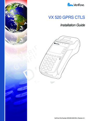
TERMINAL O VERVIEWVX 520 TerminalVX 520 TerminalThis section provides a brief description of the VX 520 terminal: The VX 520 is a high performance countertop terminal with enhancedcommunication options. The VX 520 offers several communication options, enhanced display,increased processing power, expanded memory, and two USB peripheralports.The VX 520 terminal uses a robust, sleek, and highly functional design.NOTEVeriFone ships variants of the VX 520 terminals for different markets. Yourterminal may have a different configuration from the features described in thissection.Figure 110VX 520 INSTALLATION GUIDEVX 520 Terminal
TERMINAL O VERVIEWVX 520 TerminalVX 520 Features and VX 520 terminals provide the right combination of features and functions. ThisBenefits includes a triple-track magnetic-stripe card reader, landed smart card reader,integrated PIN pad, a quiet internal thermal printer (ITP).Connectivity Host USB port Client USB port RJ-11 port RS-232 port Ethernet PortNOTEThe connectivity ports are easily accessible from the underside of the terminal.NOTEVeriFone ships variants of the VX 520 terminals for different markets. Yourterminal may have a different configuration from the features described in thissection.Performance 400 MHz Processor (CPU) Increased memory (128 MB Flash, 32 MB RAM) 128/64 white backlit LCD Fastest encryption/decryption appliance on the market Backlit keypadSecurity Increased Security (PCI 2.0) SDA DDA encryption ready Leading ECC Performance BenchmarkForm Factor The VX 520 is ergonomically designed to fit both the traditional countertop andhand-over models.VX 520 INSTALLATION GUIDE11
TERMINAL O VERVIEWVX 520 TerminalExceptional Ease of Use The bold design is sleek, stylish, and lightweight for conveniently handing theterminal to the consumer for PIN entry or other input. An intuitive ATM-style interface, a large 8-line by 21-character backlit displaywith backlit keypad, and extra-size menu prompts, simplify training and reducehelp desk calls. The integrated printer simplifies paper loading and reduces paper jams. The triple-track, high-coercivity card reader handles most magnetic stripecards.Countertop Performance in a Hand-Over Design The 32-bit processing and multi-tasking capabilities ensures fast processing ofpayment, payment-related, and value-added applications. Exceptional display and printer graphics-handling capabilities that quicklyrender logos, graphical fonts, and character-based languages. The VX 520 series of terminals ensures uncompromising reliability fromVeriFone, the worldwide leader in POS solutions.True Multi-Application Capability The VX 520 terminal offers 32 MB of RAM, and 128 MB Flash memory, whichsupports multiple applications on a single terminal. The primary smart card reader and the MSAMs safeguard sensitive financialdata and support multiple smart card schemes. VX 520 terminals and SoftPay EMV software are certified for EMV Level 1 andLevel 2 Type approval for smart card solutions. The Verix V or Vx EMV Libraryprovides development of other EMV-compliant applications. 12VX 520 INSTALLATION GUIDEThe VeriShield security architecture meets published specifications for PCIPED and provides sophisticated file authentication to prevent execution ofunauthorized software on VX 520 terminals.
TERMINAL O VERVIEWVX 520 Sprocket TerminalVX 520 Sprocket This section provides a brief description of the VX 520 Sprocket terminal:Terminal An optional configuration of the VX 520 replaces the thermal printer with asprocket printer, an additional telephone port (RJ-11) and power buttons. The VX 520 Sprocket configuration enjoys the same communication andperformance capabilities as the standard VX 520.The VX 520 Sprocket terminal uses a robust, highly functional design.Figure 2VX 520 Sprocket TerminalVX 520 Sprocket VX 520 Sprocket terminals provide the right combination of features andFeatures and functions. This includes a triple-track magnetic-stripe card reader, landed smartBenefits card reader, integrated PIN pad, and a dot-matrix impact printer.Connectivity Host USB port Client USB port RJ-11 ports (1 telco and 1 line) RS-232 port Ethernet PortVX 520 INSTALLATION GUIDE13
TERMINAL O VERVIEWVX 520 Sprocket TerminalPerformance 400 MHz Processor (CPU) 160 MB total memory (128 MB Flash, 32 MB RAM) 128/64 white backlit LCD Fastest encryption/decryption appliance on the marketSecurity PCI PED 2.0 securityExceptional Ease of Use Soft power buttons. Pressing the Enter key for at least three seconds powersterminal on, while pressing the Cancel key for at least four seconds powersthe terminal off. An intuitive ATM-style interface, a large 8-line by 21-character backlit display,and extra-size menu prompts, simplify training and reduce help desk calls. The integrated printer simplifies paper loading and reduces paper jams. The triple-track, high-coercivity card reader handles most magnetic stripecards.Countertop Performance with 76 mm Punch Hole Paper Support The 32-bit processing and multi-tasking capabilities ensures fast processing ofpayment, payment-related, and value-added applications. Exceptional display and printer graphics-handling capabilities that quicklyrender logos, graphical fonts, and character-based languages. The VX 520 Sprocket series of terminals ensures uncompromising reliabilityfrom VeriFone, the worldwide leader in POS solutions.True Multi-Application Capability14 The VX 520 Sprocket terminal offers 32 MB of RAM, and 128 MB Flashmemory, which supports multiple applications on a single terminal. The primary smart card reader and the MSAMs safeguard sensitive financialdata and support multiple smart card schemes. VX 520 Sprocket terminals and SoftPay EMV software are certified for EMVLevel 1 and Level 2 Type approval for smart card solutions. The Verix V or VXEMV Library provides development of other EMV-compliant applications. The VeriShield security architecture meets published specifications for PCIPED and provides sophisticated file authentication to prevent execution ofunauthorized software on VX 520 Sprocket terminals.VX 520 INSTALLATION GUIDE
CHAPTER 2Terminal SetupUse this chapter to set up and use your VX 520 terminal. Package contents andsetup procedures may vary for different VX 520 models: The standard VX 520uses thermal paper rolls while the VX 520 Sprocket uses carbonized papersheets. Use the procedures in this section to set up and use your terminal. VX 520 Setup VX 520 Sprocket SetupVX 520 INSTALLATION GUIDE15
TERMINAL S ETUPVX 520 SetupVX 520 SetupThis section describes the setup procedures for the VX 520 terminal. You willlearn about: Selecting Terminal Location Unpacking the Shipping Carton Examining Terminal Features Establishing Telephone Line Connections Installing a Paper Roll in the Printer Installing/Replacing MSAM Cards Connecting Optional Devices Connecting the Terminal Power Pack Privacy Shield (Optional) Using the Smart Card Reader Using the Magnetic Card ReaderSelecting Terminal Use the following guidelines when selecting a location for your VX 520 terminal.LocationEase of Use Select a location convenient for both merchant and cardholder. Select a flat support surface, such as a countertop or table. Select a location near a power outlet and a telephone/modem line connection.For safety, do not string the power cord in a walkway or place it across awalkway on the floor.Environmental Factors Do not use the terminal where there is high heat, dust, humidity, moisture, orcaustic chemicals or oils. Keep the terminal away from direct sunlight and anything that radiates heat,such as a stove or motor. Do not use the terminal outdoors.CAUTION16VX 520 INSTALLATION GUIDEThe terminal is not waterproof or dustproof, and is intended for indoor use only.Any damage to the unit from exposure to rain or dust may void any warranty.
TERMINAL S ETUPVX 520 SetupElectrical Considerations Avoid using this product during electrical storms. Avoid locations near electrical appliances or other devices that causeexcessive voltage fluctuations or emit electrical noise (for example, airconditioners, electric motors, neon signs, high-frequency or magnetic securitydevices, or computer equipment). Do not use the terminal near water or in moist conditions.Unpacking the Open the shipping carton and carefully inspect its contents for possible tamperingShipping Carton or shipping damage. The VX 520 terminal is a secure product and any tamperingmay cause the device to cease to function properly.To unpack the 1shipping cartonRemove and inspect the following items: Terminal Power pack Telephone line cord Power cord2 Remove all plastic wrapping from the terminal and other components.3 Remove the clear protective film from the LCD screen.CAUTIONDo not use a terminal that has been damaged or tampered with. The VX 520terminal comes equipped with tamper-evident labels. If a label or componentappears damaged, please notify the shipping company and your VeriFonerepresentative or service provider immediately.4 Save the shipping carton and packing material for future repacking or movingthe terminal.VX 520 INSTALLATION GUIDE17
TERMINAL S ETUPVX 520 SetupExamining Terminal Before you continue the installation process, notice the features of the VX 520Features terminal (see Figure 3).INTERNAL THERMALPRINTERPRINTER DOORLATCHSERRATED METALSTRIPTERMINAL DISPLAYMAGNETICCARD READERATM-STYLEFUNCTION KEYSALPHA KEYPROGRAMMABLEFUNCTION KEYSTELEPHONE-STYLEKEYPADENTER KEYCANCEL KEYBACKSPACE/CLEAR KEYSMART CARD READERFigure 3NOTEVX 520 Terminal Features (Front Panel)VeriFone ships variants of the VX 520 terminals for different markets. Yourterminal may have a different configuration from the features described in thissection.Front PanelThe front panel includes the following features: A terminal display, backlit LCD screen. Five types of keys:a A backlit 12-key, telephone-style keypad.b Four ATM-style function keys, labeled F1 to F4, to the right of the LCDscreen.18VX 520 INSTALLATION GUIDE
TERMINAL S ETUPVX 520 Setupc Four unlabeled, programmable function keys above the keypad.d Three color-coded function keys below thekeypad (icons at right; from left to right: CANCEL,BACKSPACE/CLEAR, ENTER).e An ALPHA key centered at the top of the keypad.A magnetic card reader, built into the right side. The icon at rightshows the proper swipe direction, with the stripe down and facinginward, toward the keypad. The VeriFone logo blue indicator LED indicates power is ON. An internal thermal printer. A smart card reader, built into the front of the terminal. The iconshown at right indicates proper card position and insertiondirection. Three SAM (security access module) compartments, built into the side ofthe terminal. The VX 520 terminal contains MSAM cardholders to supportmultiple stored-value card programs or other merchant card requirements.VeriFone ships variants of the VX 520 terminal for different markets. Your terminalmay have a different configuration. However, the basic processes described in thisguide remain the same, regardless of terminal configuration.Connection PortsTurn the terminal upside down and remove the rear cover to view the connectionports. Notice that the ports are recessed. Different ports provide connections to acommunications line, optional peripheral devices, and the power supply.Figure 4 shows how to open the rear cover of the VX 520 terminal.23 %4(NOTE Figure 4Opening the Rear CoverVX 520 INSTALLATION GUIDE19
TERMINAL S ETUPVX 520 SetupFigure 5 and Figure 6 show the connection ports for the VX 520 terminal.POWER PORTRS-232 SERIAL PORT23 RJ-11 TELEPHONE PORT%4(Figure 5VX 520 Power and Connection Ports%4(HOST USB PORTETHERNET PORT23 CLIENT USB PORTFigure 6WARNING20VX 520 INSTALLATION GUIDEAdditional VX 520 Connection PortsDo not connect the terminal to the power supply until all the peripherals areattached.
TERMINAL S ETUPVX 520 SetupTo use the The connection ports offer multiple connectivity for the VX 520 terminal. Pleaseconnection ports refer to the following list of peripheral devices for the connectivity options.Host USB Port PINpad 1000 USB Vx810 USB Barcode reader Biometric reader USB flash disk USB keyboardsEthernet Port Ethernet cable to router, hub or switchClient USB Port PC ECR/Cash registerRJ-11 Port Telephone lineRS-232 Port PINpad 1000 Vx810 PC download cable Computer ECR Check reader CTLS reader Biometric reader Barcode reader KeyboardFor information on how to attach peripheral devices, see Connecting OptionalDevices.VX 520 INSTALLATION GUIDE21
TERMINAL S ETUPVX 520 SetupEstablishing Connect the telephone cord to the communication port on the terminal, then routeTelephone Line it directly to a telephone wall jack (see Figure 7). This is a direct connection andConnections the line is dedicated to the terminal.RJ-1123 (%4Figure 7WARNINGVX 520 Direct Telephone ConnectionTo reduce the risk of fire, use only No. 26AWG or larger UL Listed or CSACertified Telecommunication Line Cord.Installing a Paper Before you can process transactions that require a receipt or record, you mustRoll in the Printer install paper in the printer.The VX 520 uses a roll of single-ply, thermal-sensitive paper for either the 38 mmor the 49 mm-diameter version.A pink out-of-paper indicator line appears on the edge of the paper approximately18 inches before the end of the roll. After this line appears, there is enough paperremaining on the roll to conclude at least one transaction.CAUTIONPoor-quality paper can jam the printer and create excessive paper dust. To orderhigh-quality VeriFone paper, refer to Accessories and Documentation.Store thermal paper in a dry, dark area. Handle thermal paper carefully: impact,friction, temperature, humidity, and oils affect the color and storagecharacteristics of the paper.Never load a roll of paper with folds, wrinkles, tears, or holes at the edges.22VX 520 INSTALLATION GUIDE
TERMINAL S ETUPVX 520 SetupTo install a paper roll 1Hook your finger under the latch and lift up to swing the paper roll cover open(see Figure 8).Figure 8Opening the Printer Cover2 Remove any partial roll of paper in the printer tray by lifting it up.3 Loosen the glued leading edge of the new paper roll or remove the protectivestrip. Unwind the paper roll past any glue residue.4 Hold the roll so the paper feeds from the bottom of the roll.5Drop the paper roll into the printer tray.Figure 9Loading Paper Roll6 Pull paper up past the glue residue.VX 520 INSTALLATION GUIDE23
TERMINAL S ETUPVX 520 Setup7 Close the paper roll cover by gently pressing directly on the cover until it clicksshut, allowing a small amount of paper past the glue residue to extend outsidethe printer door. (see Figure 10).CAUTIONTo prevent the paper roll cover from damaging the print roller, always gentlypress down on the printer dust cover to close it.Figure 10Closing Paper Roll Cover8 Tear the paper off against the serrated metal strip in the printer.NOTEFor paper ordering information, refer to Accessories and Documentation.Installing/Replacing When you first receive your VX 520 terminal, you may need to install one or moreMSAM Cards MSAM cards or you may need to replace old cards.CAUTION24VX 520 INSTALLATION GUIDEObserve standard precautions when handling electrostatically sensitive devices.Electrostatic discharges can damage this equipment. VeriFone recommendsusing a grounded anti-static wrist strap.
TERMINAL S ETUPVX 520 SetupTo install or replace 1MSAMsRemove the power cord from the power outlet.2 Place the terminal upside down on a soft, clean surface to protect the displayfrom scratches.3 Press the unlocking button and then lift the rear cover to access the MSAMcardholder panel.23 %4(Figure 11Opening VX 520 Rear Cover4 Hold the MSAM cardholder panel, grasp firmly and pull upward to expose theMSAM slots.(%4 23Figure 12Removing MSAM Cover4 Remove any previously installed MSAM card by sliding the card from theMSAM cardholder.VX 520 INSTALLATION GUIDE25
TERMINAL S ETUPVX 520 Setup5 Install an MSAM card by carefully sliding it into the slot until it is fully inserted.(%4 23Figure 13NOTEInstalling an MSAM CardBefore inserting the MSAM card, position it as shown in Figure 13, with the card’sgold contacts facing down. The cardholder connector base has an imageresembling the notched corner of an MSAM card to ensure the card is positionedcorrectly.6 Close the MSAM cardholder panel, and then replace the terminal rear cover.Connecting The VX 520 terminal supports some peripheral devices designed for use withOptional Devices electronic point-of-sale terminals.Before connecting any peripheral device, remove the power cord from theterminal and ensure that the green indicator LED is not lit. Reconnect the powercord only after you are finished connecting the peripheral device(s). For completeinformation about peripheral installation and use, refer to the user documentationsupplied with those devices.CAUTIONDifferent terminals support different devices, so for more information aboutoptional devices, please contact your VeriFone distributor.26VX 520 INSTALLATION GUIDE
TERMINAL S ETUPVX 520 SetupOptional Device ConnectionsThe VX 520 terminal has a port that can operate either as a PIN pad port or anRS-232 port, depending on the power source available.Connecting the
NOTE VeriFone ships variants of the VX 520 terminals for different markets. Your terminal may have a different configuration from the features described in this section. TERMINAL OVERVIEW VX 520 Terminal VX 520 INSTALLATION GUIDE 11 VX 520 Features and Benefits