Transcription
Optical Fiber CableApplication NoteNETWORK TOPOLOGIESAuthorJohn Peter & Timo PerttunenIssuedJune 2014AbstractNetwork topology is the way various components of a network (like nodes, links, peripherals, etc) arearranged. Network topologies define the layout, virtual shape or structure of network, not only physicallybut also logically. The way in which different systems and nodes are connected and communicate with eachother is determined by topology of the network. Topology can be physical or logical. Physical Topology isthe physical layout of nodes, workstations and cables in the network; while logical topology is the wayinformation flows between different components. Distances between nodes, physical interconnections,transmission rates, and/or signal types may differ between two networks, yet their topologies may beidentical.KeywordsTopology, P2P, Bus, Ring, Star, Mesh, Tree, , PON, Ethernet.sterlitetechnologies.comSterlite is a registered trademark of Sterlite Technologies Limited
Optical Fiber Cable1 Topology - GeneralNetwork topology is usually a schematic description of the arrangement of a network, including its nodesand connecting lines. There are two ways of defining network geometry: the physical topology and thelogical (or signal) topology. Physical topology describes where the network's various components like itsdevices and cables are placed and installed, while logical topology explains network's information (data)flow and transmission, apart from physical design. Distances between nodes, physical interconnections,transmission rates, and/or signal types may differ between two networks, yet their topologies may beidentical.FTTH example: Nodes in FTTH has one or more physical links to other devices in the network and drawinglinks, network designing, between these nodes in a map gives the physical topology for the network.Logical topology is designed by mapping and drawing how the data transmits through the network; linespeeds, wavelengths, signaling etc.Two basic categories of network topologies:· Physical topology· Logical topologyApplication NoteThe physical topology and its capabilities is determined by network active devices and media like cabletype(s), the level of control or fault tolerance desired, and the Capex/Opex costs related to its passive andactive infrastructure.The logical topology in contrast, is the way that the signals act on the network media, or the way that thedata passes through the network from one device to the next without regard to the physicalinterconnection of the devices. A network's logical topology is not necessarily the same as its physicaltopology. For example, the original twisted pair Ethernet using repeated hubs was a logical bus topologywith a physical star topology layout. Also Token Ring is a logical ring topology, but is wired as physical startopology from the Media Access Unit.The logical classification of network topologies generally follows the same classifications as those in thephysical classifications of network topologies but describes the path that the data takes between nodesbeing used as opposed to the actual physical connections between nodes. The logical topologies aregenerally determined by network protocols as opposed to being determined by the physical layout ofcables, wires, and network devices or by the flow of the electrical or optical signals, although in many casesthe paths that the signals take between nodes may closely match the logical flow of data, hence theconvention of using the terms logical topology and signal topology interchangeably.Logical topologies are able to be dynamically reconfigured by special types of equipment such as routersand switches.sterlitetechnologies.comSterlite is a registered trademark of Sterlite Technologies Limited
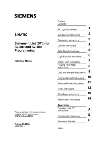
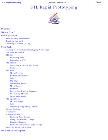
Optical Fiber CableThe basic network topologies are:· Point-to-point· Bus· Star· Ring or circular· Mesh· Tree· HybridBUSStarRingMeshTreeDiagram of different network topologies.Application Note1.1 Point-to-pointThe most basic and commonly in POTS (Plain Old Telephone Systems) systems used topology is apermanent link between two endpoints. Its switched point-to-point topology is the basic model ofconventional telephony systems. Point-to-point network is designed to give direct and dedicatedcommunications between the two endpoints.Permanent (dedicated)Easiest to understand, of the variations of point-to-point topology, is a point-to-point CommunicationsChannel that appears permanently between the two endpoints. Within many Switchedtelecommunications systems,it is possible to establish a permanent circuit. One example might be atelephone in the lobby of a public building, which is programmed to ring only the number of a telephonedispatcher.Switched:Using Circuit-switching or Packet-switching technologies, a point-to-point circuit can be set updynamically, and dropped when no longer needed. This is the basic mode of conventional telephony.sterlitetechnologies.comSterlite is a registered trademark of Sterlite Technologies Limited
Optical Fiber Cable1.2 BusBus networks use a common backbone to connect all devices. A single cable, the backbone functions as ashared communication medium that devices attach or tap into with an interface connector. A devicewanting to communicate with another device on the network sends a broadcast message onto the wirethat all other devices see, but only the intended recipient actually accepts and processes the message. Sincethe bus topology consists of only one wire, it is rather inexpensive to implement when compared to othertopologies. However, the low cost of implementing the technology is offset by the high cost of managingthe network. Additionally, since only one cable is utilized, it can be the single point of failure. If the networkcable is terminated on both ends and when without termination data transfer stop and when cable breaks,the entire network will be down.Linear busApplication NoteThe type of network topology in which all of the nodes of the network are connected to a commontransmission medium which has exactly two endpoints – all data that is transmitted between nodes in thenetwork is transmitted over this common transmission medium and is able to be received by all nodes in thenetwork simultaneously.Distributed busThe type of network topology in which all of the nodes of the network are connected to a commontransmission medium which has more than two endpoints that are created by adding branches to the mainsection of the transmission medium – the physical distributed bus topology functions in exactly the samefashion as the physical linear bus topology (i.e., all nodes share a common transmission medium).1.3 Starsterlitetechnologies.comSterlite is a registered trademark of Sterlite Technologies Limited
Optical Fiber CableIn networks with a star topology, each host or client is connected to a central hub (switch, router, server)with a point-to-point connection. All traffic that traverses the network passes through the central hub. Thehub acts as a signal router. The star topology is considered the easiest topology to design and implement.An advantage of the star topology is the simplicity of adding additional nodes. The primarydisadvantage of the star topology is that the hub represents a single point of failure though this 'device' iscommonly duplicated (redundancy).Extended starA type of network topology in which a network that is based upon the physical star topology has one ormore repeaters between the central node (the 'hub' of the star) and the peripheral or 'client' nodes. Therepeaters are used to extend the maximum transmission distance of the point-to-point links between thecentral node and the peripheral nodes beyond that which is supported by the transmitter or the physicallayer (cables, RF link).Distributed StarA type of network topology that is composed of individual networks that are based upon the physical startopology connected in a linear fashion – i.e., 'daisy-chained' – with no central or top level connection point(e.g., two or more 'stacked' hubs, along with their associated star connected nodes).Application Note1.4 RingA network topology that is set up in a circular fashion in which data travels around the ring in one directionand each device on the ring acts as a repeater to keep the signal strong as it travels. Each device incorporatesa receiver for the incoming signal and a transmitter to send the data on to the next device in the ring. When adevice sends data, it must travel through each device on the ring until it reaches its destination. Every nodeis a critical link.sterlitetechnologies.comSterlite is a registered trademark of Sterlite Technologies Limited
Optical Fiber Cable1.5 MeshThe mesh network topology employs either of two schemes, called full mesh and partial mesh. In the fullmesh topology, each workstation is connected directly to each of the others. In the partial mesh topology,some workstations are connected to all the others, and some are connected only to those other nodes withwhich they exchange the most dataFully connected networkA fully connected network is a Communication network in which each of the nodes is connected to eachother. A fully connected network doesn't need to use Switching nor Broadcasting. However, its majordisadvantage is that the number of connections grows quadratically with the number of nodes, per theformulaApplication Notec n(n-1)2and so it is extremely impractical for large networks. A two-node network is technically a fully connectednetwork.Partially connectedThe type of network topology in which some of the nodes of the network are connected to more than oneother node in the network with a point-to-point link – this makes it possible to take advantage of some ofthe redundancy that is provided by a physical fully connected mesh topology without the expense andcomplexity required for a connection between every node in the network.sterlitetechnologies.comSterlite is a registered trademark of Sterlite Technologies Limited
Optical Fiber Cable1.6 TreeTree topology is a combination of Bus and Star topology. This particular type of network topology is basedon a hierarchy of nodes. The highest level of any tree network consists of a single, 'hub' node, this nodeconnected to multiple nodes in the level below by(a point-to-point link(s). These lower level nodes are alsoconnected to a single or multiplenodes in the next level down. Tree networks are not constrained to any number of levels, but as treenetworks are a variant of the bus network topology, they are prone to network failures when connections ina higher level of nodes fail/suffer damage. Each node in the network has a specific, fixed number of nodesconnected to it at the next lower level in the hierarchy, this number referred to as the 'branching factor' ofthe tree.Application Note1.7 HybridHybrid networks use a combination of any two or more topologies, in such a way that the resulting networkdoes not exhibit one of the standard topologies (e.g., bus, star, ring, etc.). A hybrid topology is alwaysproduced when two different basic network topologies are connected. Two common examples for Hybridnetwork are: star ring network and star bus network· A Star ring network consists of two or more star topologies connected using a centralized hub.· A Star Bus network consists of two or more star topologies connected using a bus trunk (the bustrunk serves as the network's backbone).2 CentralizationThe star topology reduces the probability of a network failure by connecting all of the peripheral nodes(computers, etc.) to a central node. When the physical star topology is applied to a logical bus network suchas Ethernet, this central node broadcasts all transmissions received from any peripheral node to allperipheral nodes on the network. All peripheral nodes may thus communicate with all others bytransmitting to, and receiving from, the central node only. The failure in a transmission line linking anyperipheral node to the central node will result in the isolation of that peripheral node from all others, but theremaining peripheral nodes will be unaffected. However, the disadvantage is that the failure of the centralnode will cause the failure of all of the peripheral nodes also (risk can be reduced by duplicating the centralnode, 'redundancy').sterlitetechnologies.comSterlite is a registered trademark of Sterlite Technologies Limited
Optical Fiber CableApplication NotezCentral node can be passive, when the originating node must be able to tolerate the reception of an echo ofits own transmission, and active where star network has an active central node that usually has the means toprevent echo-related problems.A tree topology can be viewed as a collection of star networks arranged in a hierarchy. It has individualperipheral nodes which are required to transmit to and receive from one other node only and are notrequired to act as repeaters or regenerators. Unlike the star network, the functionality of the central nodemay be distributed.Note: To alleviate the amount of network traffic that comes from broadcasting all signals to all nodes, moreadvanced central nodes were developed that are able to keep track of the identities of the nodes that areconnected to the network. These network switches will "learn" the layout of the network by "listening" oneach port during normal data transmission, examining the data packets and recording theaddress/identifier of each connected node and which port it is connected to in a lookup table held inmemory. This lookup table then allows future transmissions to be forwarded to the intended destinationonly.3 DecentralizationIn a mesh topology, there are at least two nodes with two or more paths between them to provideredundant paths to be used in case the link providing one of the paths fails. This decentralization is oftenused to compensate for the single-point-failure disadvantage that is present when using a single device as acentral node (e.g., in star and tree networks).A fully connected network, or full mesh topology is a network topology in which there is a direct linkbetween all pairs of nodes. In a fully connected network with n nodes, there are n(n-1)/2 direct links.Networks designed with this topology are usually very expensive to set up, but provide a high degree ofreliability due to the multiple paths for data that are provided by the large number of redundant linksbetween nodes. This topology is mostly seen in military / tactical and other critical applications.Additional informationIf there are additional questions on this topic or other fiber optic issues, please contact Sterlite Technologiesat:Contact echnologies.comsterlitetechnologies.comSterlite is a registered trademark of Sterlite Technologies Limited
links, network designing, between these nodes in a map gives the physical topology for the network. Logical topology is designed by mapping and drawing how the data transmits through the network; line speeds, wavelengths, signaling etc. Two basic categories of network topologies: · Physical topology · Logical topology