Transcription
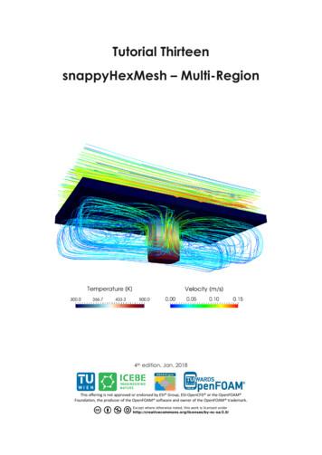
snappyHexMesh Basic Trainingmulti Region meshingsimulation of heat transfer withchtMultiRegionFoam1st edition, Aug. 2015Editor: Philipp Schretter (TU Wien)
OpenFOAM Basic TrainingsnappyHexMeshTutorial Two: Multi Region MeshingMesh creationThe procedure described in this tutorial is structured in the following order: Creation of the geometry data Tutorial on Meshing a geometry with more than one region Run an OpenFOAM simulation with the generated mesh usingchtMultiRegionFOAMObjectives The aim of the tutorial is to give a basic introduction to multi region meshing withthe meshing tool snappyHexMesh.Understanding the advantages of snappyHexMesh No commercial software package is ultimately necessary. For the meshing,the OpenFoam environment is sufficient and no further software isnecessary. The geometry can be created with any CAD program like CATIA,FreeCAD, etc. As the geometry is to be only surface data, the files need tobe in .stl, .nas or .obj. format. The meshing process can be run in parallel mode. If high computationalcapabilities are available, high quality meshes can be generated in littletime.Understanding the three basic steps of snappyHexMesh Castellation: The cells which are beyond a region set by a predefined pointare deleted Snapping: Reconstructs the cells to move the edges from inside the regionto the required boundary Layering: Creates additional layers in the boundary region.Post processingImport your simulation to ParaView. Analyze the flow field through the flange andthe heat distribution in the flange.
OpenFOAM Basic TrainingsnappyHexMeshStep by step meshingCreation of the .stl filesFor the geometry data, the CAD software CATIA was used, to create the solidgeometry. The creation of the .stl files for single region and multi-region is slightlydifferent. Either way, it is necessary, to create the .stl files as ASCII .stl and not asbinary .stl.For the multi region case, several .stl files are necessary in order to create the meshfor the flange. One Possibility is to create the surface files with CATIA with theWireframe and Surface Design tool.Another possibility is to create a solid geometry with CATIA and export the geometrydata as .stp format. This file is imported to FreeCAD to generate the .ast files. WithFreeCAD, the .stl files can be extracted from the .stp solid geometry: Open the .stpgeometry file in the draft workbench and select the object in the tree view viewsection. Then click on Downgrade in the combo view view-section. This gives a listof all faces of the geometry, which can be selected and exported as .ast format. InFreeCAD, it's necessary to distinguish between .stl, which is binary .stl, and .ast,which is ASCII .stl.Figure 1 Select the surfaces from a solid geometry
OpenFOAM Basic TrainingsnappyHexMeshIn the case which was prepared for this tutorial, the dimensions from from the .stl filesexported from the CAD software are in meters. To convert the dimensinos, the opensource software Blender can be used. Therefore, import the .stl files and use the scaletool with a factor 0.001 to convert from m to mm. To export the file, it is necessary totick the box for Ascii to save the .stl file in ascii format. Otherwise, OpenFoam won'tbe able to deal with the file.In the multi region case, the header line and the base line of the .stl files, exportedfrom blender need to be updated with an appropriate labelling. For example forheader line for the .stl for inlet 1 is renamed to solid inlet 1.In order to create a .stl from a geometry which is already available in gambit, thegeometry data can be exported in .stp or alternatively in .igs format. Afterwards,the .stp or .igs (msbo) file can be imported to FreeCAD and converted via exportas .stl.The technical drawing with the dimensions of the geometry for this tutorial isdepicted below.
OpenFOAM Basic TrainingsnappyHexMesh
OpenFOAM Basic TrainingsnappyHexMeshMulti region layer meshing is used to mesh geometries with several regions. For thiscase, the region inside the flange is meshed (region 0) as well as the flange itself(region 1). Subsequent to the meshing, an OpenFOAM simulation with the solverchtMultiRegionFoam is run with the created mesh.For multi region mehsing, the files in the folders constant and system are basically thesame as for single region meshing. The changes in snappyHexMeshDict andsurfaceFeatureExtractDict are described below. Only the relevant changes, whichwere used in the sample flange case, are commented in the snappyHexMeshDict. Formore information see the literature in [1], [2], [3], [4].-snappyHexMeshDict// * * * * * * * * * * * * * * * * * * * * * * * * * * * * * * * * * * e surfaces to apply boundary conditions later on for an OpenFoamSimulationgeometry{insideDomain.stl{type triSurfaceMesh;name inside;}outsideDomain.stl{type triSurfaceMesh;name outside;}inlet 1.stl{type triSurfaceMesh;name inletone;}inlet 2.stl{type triSurfaceMesh;name inlettwo;}outlet.stl{type triSurfaceMesh;name ocalCells 8000000;maxGlobalCells 10000000;minRefinementCells 0;maxLoadUnbalance 0.0;nCellsBetweenLevels 1;The level number can be the source of an error while running themeshing process inparallel, where several regions are created, which belong neither tothe insideDomain nor to outsideDomain.features(
OpenFOAM Basic TrainingsnappyHexMesh{file "insideDomain.eMesh";level 3;}{file "outsideDomain.eMesh";level 3;});All surfaces defined in the geometry subdirectory must be listed here.List of the surfaces, which need to be listed in in the boundary filesIn e{It is necessary to define a specific point anywhere inside theregion. Simply labelling the cellZoneInside as inside is notsufficient.level (3 3);faceZone insideFaces;cellZone insideZone;cellZoneInside insidePoint;insidePoint (0.0 0.0 0.0);}outside{It is necessary to define a specific point anywhere inside theinside the region. Simply labelling the cellZoneInside asinside is not sufficient.level (3 3);faceZone outsideFaces;cellZone outsideZone;cellZoneInside insidePoint;insidePoint (0.010 0.0 0.0);}inletone{No empty boundary. Define inlet/outlet as patchlevel (0 0);patchInfo{type patch;}}inlettwo{No empty boundary. Define inlet/outlet as patchlevel (0 0);patchInfo{type patch;// possibly also define inGroups}}outlet{No empty boundary. Define inlet/outlet as patch.level (0 0);patchInfo{type patch;possibly also define inGroups}}}resolveFeatureAngle is an important setting. Edges, whose adjacentsurface normals are at an angle higher than the value set, areresolved. The lower the value, the better is the resolution at sharpedgesresolveFeatureAngle 30;
OpenFOAM Basic TrainingsnappyHexMeshIn this case, no refinement regions are defined.refinementRegions{}The point is chosen inside the surface domain of the flange. Hence,snappy creates the internal mesh.In contrast to that, choosing the locationInMesh point outside theflange domain, lets snappy mesh the part between the surface and theblockMesh.locationInMesh (0 0 0);allowFreeStandingZoneFaces true;}SNAPPINGImportant parameters are number of mesh displacement iterations,nSolveIter and the number of feature edge snapping tch 5;tolerance 1.0;nSolveIter 300;nRelaxIter 10;nFeatureSnapIter 5;implicitFeatureSnap false;explicitFeatureSnap true;//multiRegionFeatureSnap not necessary in this casemultiRegionFeatureSnap false;}LAYERINGaddLayersControls{relativeSizes false;layers{The layers are added on the inside region of the flangeinsideZone to outsideZone{define the number of surface layers on the inside of theflangenSurfaceLayers 3;}}define the expansion ratio of the surface layersexpansionRatio 1.005;define the min and the final thickness of the surface layersfinalLayerThickness 0.0001;minThickness 0.00005;nGrow 0;featureAngle 85;slipFeatureAngle 25;nRelaxIter 5;nSmoothSurfaceNormals 4;nSmoothNormals 3;nSmoothThickness 10;maxFaceThicknessRatio 0.5;maxThicknessToMedialRatio 0.2;minMedianAxisAngle 90;nBufferCellsNoExtrude 0;LayerIter : If not snapped smoothly enough, the max number of layerAddition iteration can be increasednLayerIter 50;}meshQualityControls{#include "meshQualityDict"nSmoothScale 4;errorReduction 0.75;}writeFlags(scalarLevels
OpenFOAM Basic lerance 1e-6;// ****************** //-surfaceFeatureExtractDict// * * * * * * * * * * * * * * * * * * * * * * * * * * * * * * * * * * face;All edges are refined, whose surface normals include angles with lessthan the angle specified. For the included angels, a special level ofrefinement can be set in the snappyHexMeshDict in the ffs{includedAngle120;}writeObjno;}// ****************** //Basically, .stl files for the snappyHexMesh tool have to encompass a closedgeometry. This is especially important for geometries which consist of severaldifferent .stl files to create one closed geometry. Therefore it is important to take careespecially of the exact dimensions of the parts of the geometry while creating the .stlfiles,To ensure that the mesh from two domains, stl.inside, and stl.outside, is compatibleand connected, it is necessary, that both domains are created from the same surfaceswhich are shared with both domains. In this case, the .stl. file flange inside is part ofthe domains stlinside as well as of stloutside.This is also depicted in the following:
OpenFOAM Basic TrainingsnappyHexMeshIn order to set the boundary types in the boundary files in/constant/polyMesh/boundary and also to generate a mesh for the inlets, outets andwalls, it is necessary that the .stl files for those boundaries are located in/constant/triSurface.All those files must be listed in the geometry subdirectory as well as in therefinementSurfaces subdirectory in the snappyHexMeshDict.The following commands combine the .stl files for the region inside the flange,stlinside, and for the region of the flange itself, stloutside. The files are taken from thefolder cad in the main directory.In figure XX, the combined stl files are depicted. The resulting file insideDomain.stl
OpenFOAM Basic TrainingsnappyHexMeshfor the region 0 consists of the stls for the wall inside the flange (black) for the inlet 1(blue) for the inlet 2 (green) and for the outlet (red).he resulting file outsideDomain.stl for the region 1 consists of the sls for the walloutside the flange.The resulting file outsideDomain.stl for the region 1 consists of the stls for the walloutside the flange (orange) and for the wall inside the flange (black). cat cad/flange stl/stloutside/* constant/triSurface/outsideDomain.stl cat cad/flange stl/stlinside/* constant/triSurface/insideDomain.stlFigure 2 Surface geometry of the flange domain inside (black) and outside (orange)The background mesh is created with blockMesh. blockMeshThe block mesh for the multi region case is the same as for the single region case with30 cells in x- and y direction and with 20 cells in z direction.Also in the multi region case, it is very important to create perfect cubes in the firstplace to ensure that the sharp edges are refined properly. Otherwise, highly skewedcells could be generated while the snapping process.
OpenFOAM Basic TrainingsnappyHexMeshFigure 3 Block mesh for flangeThe dimensions of the blockmesh are as follows.// * * * * * * * * * * * * * * * * * * * * * * * * * * * * * * * * * * * * * //convertToMeters 1;vertices((-0.03 -0.03 -0.02)(0.03 -0.03 -0.02)(0.03 0.03 -0.02)(-0.03 0.03 -0.02)(-0.03 -0.03 0.02)(0.03 -0.03 0.02)(0.03 0.03 0.02)(-0.03 0.03 0.02));blocks(hex (0 1 2 3 4 5 6 7) (30 30 20) simpleGrading (1 1 1));.// *********************** //Equal to the single region case, the command surfaceFeatureExtract createsthe .eMesh files from the .stl-files with the geometry data. Also the folderextendedFeatureEdgeMesh is created in the /constant directory.The creation of .eMesh files with the command surfaceFeatureExtract is notobligatory. This step is only necessary, if certain edges need to be refined. surfaceFeatureExtract
OpenFOAM Basic TrainingsnappyHexMeshAs the meshing process is run in parallel, the geometry needs to be decomposed priorto run snappyHexMesh. Depending on the number of subdomains, defined in thedecomposeParDict, the processor folders are created accordingly.Note: It is recommended, not to use the scotch method to decompose the region.Rather, the hierarchical or the simple method should be used. In case of scotchmethod, errors can occur while executing snappyHexMesh or while reconstructing themesh, so that more domains are reconstructed than have been decomposed before.Nevertheless, using snappyHexMesh for meshing geometries in parallel, can stillproduce errors if the refinement levels of the edges or surfaces in the respectivesubdirectories in snappyHexMeshDict is set too high.After running the command reconstructParMesh, the following message appearsin the terminal window:This is an experimental tool, which tries to merge individual processor meshes backinto one master mesh. .Not well tested & use at your own risk!In case, additional domains are created, even after decomposing the region with thehierarchical - or with the scotch method, the geometry can still be meshed on oneprocessor only.In this case, the domain is divided into 2 subdomains, which is also indicated by thecommand mpirun -np 2, whereas np stands for number of processors. decomposePar
OpenFOAM Basic TrainingsnappyHexMesha) Running snappyHexMeshDict step by step (onlyrecommended for learning the tool or finding errors)Step 1 castellatedMeshIn the following, the execution of snappyHexMeshDict is described step by step.This procedure is only useful to see the intermediate steps or to find bugs in themeshing process. Therefore, the steps snap or layering can be set to false. RunningsnappyHexMeshDict completely is described in the next section.If in the snappyHexMeshDict, castellatedMesh and snap are set to true, the folders 1and 2 are created after running the command snappyHexMesh in parallel. Folder 1contains the mesh files after the step castellatiedMesh and folder 2 after the step snap. mpirun -np 2 snappyHexMesh -parallelAfter running snappyHexMesh in parallel, the mesh data is located in the differentprocessor folders. This data needs to be reconstructed. The following commandreconstructs the mesh after the step castellatedMesh. reconstructParMesh -time 1After performing these steps, the flange is meshed, but still the outside mesh needs tobe removed. As the point locationInMesh in the snappyHexMeshDict file is definedinside the flange domain, no mesh is removed by snappyHexMesh and therefore hasto be removed manually.Figure 4 Mesh after reconstructParMesh
OpenFOAM Basic TrainingsnappyHexMeshIn the file boundary in the folder /1/constant/polyMesh, are 4 entries with zeronumber of faces: inside, inside slave, outside, outside slave. Those entries areremoved by snappyHexMesh while performing the command below.Occasionally, the entries XXX slave are not removed and still remain in theboundary files. The following steps can be attempted to avoid those entriesrename the header – and bottome lines in the .stl files and remove the labelingafter 'solid'.add the entries with the .stl files to both subdirectories in thesnappyHexMeshDict, geometry and refinementSurfaces. splitMeshRegions -cellZones -overwriteIn order to display the geometry with paraview, the mesh files must be copied to theconstant directory. cp -r 1/*constant/Figure 5 Mesh after splitMeshRegionsThe folder domain0 contains the mesh which remains after splitting the block meshfrom the flange geometry. These mesh files as well as the block mesh from thepolyMesh folder can be deleted so that only the flange mesh remains. As paraviewdisplays mesh files from all polyMesh folders, also the folder from the time step 2 isremoved. rm-rconstant/polyMeshsystem/domain0 1/domain01/polyMeshconstant/domain0
OpenFOAM Basic TrainingsnappyHexMeshFigure 6 Flange mesh after removing domain0 and polyMesh with domain of theslice(red rectangle)Figure 7 Slice view of the Flange after step castellatedMeshOccasionally, the surface of the geometry seems to have holes while displaying a Sliceview in paraview. In this case, the tool Crinkle slice can be used to remove the holes,which are mostly attributed due to triangular cells, intersecting the surface.
OpenFOAM Basic TrainingsnappyHexMeshStep 2 snapThe following command reconstructs the mesh after the step snap. reconstructParMesh -time 2If the geometry is both, castellated and snapped, also the following command can beused to reconstruct the mesh after the step snap. reconstructParMesh -latestTimeThe following commands are similar to the step castellatedMesh, except that the meshfiles are copied and removed from folder 2 instead of folder 1. splitMeshRegions -cellZones -overwrite cp -r 2/* constant/To display only the mesh of the flange, without the blockmesh, remove the folderspolyMesh and domain0. The mesh between the .stl files and the blockmesh is labelledas domain0. rm-rconstant/polyMeshsystem/domain0 2/domain02/polyMeshconstant/domain0Figure 8 Slice view of the Flange after step snap
OpenFOAM Basic TrainingsnappyHexMeshb) Running snappyHexMeshDict without intermediate stepsThis chapter includes the chapter step 3 addLayers. As step 3 is the last step itcoincides with running the case all in once.In order to prevent the creation of the folders 1, 2 (and 3) and only keep the final timestep folder with the final mesh, the command -overwrite can be added aftersnappyHexMesh. In this case, only one folder, 0, is created with the files pointLeveland cellLevel. The mesh data in this case is located in constant/polyMesh. mpirun -np 2 snappyHexMesh -parallel -overwriteThe following command reconstructs the final mesh, depending on the settings insnappyHexMeshDict.If for example castellatedMesh an snap are set on true in the snappyHexMeshDict,only the snapped mesh is reconstructed and stored, whereas the intermediate step snapis overwritten.If for example castellatedMesh, snap and addLayers are set on true in thesnappyHexMeshDict, only the layered mesh is reconstructed and stored and theprevious intermediate steps castellatedMesh and snap are overwritten.In the case at hand for this tutorial, the layers are only necessary on the fluid sidewhich is labelled insideZone. The snappyHexMesh tools needs to have the files,which have to be layered in the constant/polyMesh directory. Thereofre, in this case,only the steps castellatedMesh and snap are set to true, as these steps are applied tothe whole mesh. reconstructParMesh -constant splitMeshRegions -cellZones -overwriteAs already mentioned above, the mesh around the flange is deleted with the followingcommand. Even so the files cellToRegion, as they are not needed in the furtherprocess. rm -rf constant/domain0 system/domain0 rm -rf constant/cellToRegion constant/polyMesh rm -rf 0/domain0 ne/cellToRegion rm -rf processor*After reconstructing the mesh, only the mesh files of insideZone, which is the zone tobe layered, are copied to the /constant/polyMesh folder.
OpenFOAM Basic TrainingsnappyHexMesh mv constant/insideZone/polyMesh constant/polyMeshOnly layering is set to true in the snappyHexMeshDict. sed -i -e 18c"castellatedMeshfalse;" system/snappyHexMeshDict sed -i -e 19c"snapfalse;" system/snappyHexMeshDict sed -i -e 20c"addLayerstrue;" system/snappyHexMeshDictThe step addLayers is executed in parallel. decomposePar mpirun -np 2 snappyHexMesh -overwrite -parallel reconstructParMesh -constantAfter layering the inside of the flange domain, the snappyHexMeshDict is reset tothe previous settings. sed -i -e 18c"castellatedMeshtrue;" system/snappyHexMeshDict sed -i -e 19c"snaptrue;" system/snappyHexMeshDict sed -i -e 20c"addLayersfalse;" system/snappyHexMeshDictThe layered mesh is moved to the constant/insideZone folder. mv constant/polyMesh constant/insideZone/polyMeshRemove entries from the constant/insideZone/polyMesh/boundary file sed -i -e 42c"1" constant/insideZone/polyMesh/boundary sed -i -e 18c"4" constant/insideZone/polyMesh/boundary sed -i '45d;54,137d' constant/insideZone/polyMesh/boundaryReview the mesh quality checkMesh –region insideZone checkMesh –region outsideZone
OpenFOAM Basic TrainingsnappyHexMeshFigure 9 Slice of the flange after step addLayers
OpenFOAM Basic TrainingsnappyHexMeshRunning OpenFoam simulation with chtMultiRegionFoamCompared to previous tutorials or cases, where the mesh was created with othersoftware, in this case, several steps can be omitted.topoSet is not needed as the regions of insideDomain and outsideDomain werealready defined in the snappyHexMeshDict subdirectory geometry.Even so, the commands blockMesh and splitMeshRegions are already part of thesnappyHexMesh meshing procedure.The case is run similar to the chtMultiRegionHeater tutorial sample case which isprovided by OpenFoam.Some adjustments are necessary to run the case and check if the mesh quality issatisfactory.Copy the files alphat, epsilon, k, p, p rgh, rho, T, U from the tutorial folder/0 to the folder 0/insideZoneCopy the files p, rho, T from the tutorial folder /0 to the folder 0/outsideZoneCopy the radiationProperties and thermophysicalProperties from thetutorial folder constant/heater to the folder constant/outsideZoneCopy the g, radiationProperties, RASProperties,thermophysicalProperties, and turbulenceProperties from the tutorial folderconstant/bottomAir to constant/insideZoneCopy the regionProperties from the tutorial folder constant to the folderconstant and update the regions fluid (insideZone) and solid (outsideZone)Copy the controldict from the tutorial system folder to the folder system.Change the start time to 0, the end time to 0.01, the writeInterval to 0.0005and the max Courant number to 1.Copy the fvSchemes, fvSolution and changeDictionaryDict files from thetutorial folders system/bottomAir and system/heater to the folderssystem/insideZone and system/outsideZone respectively.Update the changeDictionaryDict of insideZone remove the entry boundary for the velocityo set the velocity internalField to 1o velocity inlet 1 is set to 1o velocity inlet 2 is set to 2o the outlet is set to zeroGradient for the temperatureo set the internal field to 298o temperature at inlet 1 is set to 773o temperature at inlet 2 is set to 573o the outlet is set to zeroGradiento insideZone to outsideZone is has typeturbulentTemperatureCoupledBaffleMixed with value uniform298 for the p rgho the internal field is set to uniform 1e5o the pressure at the outlet is set to fixedValue with value uniform
OpenFOAM Basic TrainingsnappyHexMesh1e5o inlet 1 and inlet 2 are set to zeroGradiento the boundary insideZone to outsideZone is set tofixedFluxPressure with value uniform 1e5 for the po the internal field is set to uniform 1e5o the pressure at the outlet is set to fixedValue with value uniform1e5o inlet 1 and inlet 2 are set to zeroGradiento the boundary insideZone to outsideZone is set to calculatedwith value uniform 1e5. Update the changeDictionaryDict of outsideZoneo remove the entry boundaryo set outsideZone to domain0 type zeroGradiento set outsideZone to insideZone eMixed changeDictionary -region insideZone changeDictionary -region outsideZoneDecompose the mesh for example in two domains. decomposePar -allRegionsRun the case on two cores in parallel. mpirun -np 2 chtMultiRegionFoam -parallelReconstruct the mesh and convert the data to the Visualization ToolKit format. reconstructPar –allRegions checkMesh –region insideZone checkMesh –region outsideZone foamToVTK -region insideZone foamToVTK -region outsideZone
OpenFOAM Basic e 10 Mixing inside the flange from 0.0005 to 0.01s
OpenFOAM Basic TrainingsnappyHexMesh0.0005s0.0035s
OpenFOAM Basic TrainingsnappyHexMesh0.0085s0.01sFigure 11 Heating of the flange from 0.0005 to 0.01sLiterature[1] h/[2] h[3] acksonSlidesOFW7.pdf[4] mesh#TOC-snappyHexMesh
OpenFOAM Basic Training snappyHexMesh Step by step meshing Creation of the .stl files For the geometry data, the CAD software CATIA was used, to create the solid geometry. The creation of the .stl files for single region and multi-region is slightly different. Either way, it is necessary, to create the .stl files as ASCII .stl and not as