Transcription
AS568 O-Ring Size ReferenceFreudenberg and NOK GroupO-Ring Reference: AS568 SizesYo u r Te c h n o l o g y S p e c i a l i s t
The Simrit O-Ring Design Quick ReferenceThis design quick reference guide is intended for usein specifying O-ring and groove dimensions for staticapplications with pressures less than 1500 psi.The guidelines are for the nominal condition. The minimumand maximum conditions should also be checked. Thisrequires looking at the dimensionally largest possibleO-ring in the smallest possible groove (i.e., at the hardware and O-ring tolerance stack-up) and the smallestpossible O-ring in the largest possible groove.Throughout this reference guide the term “compression”is used for describing what provides the sealing force.Since elastomers are essentially incompressible, thetechnically correct term would be “deformation.”Compression is used, as it is the more commonly usedterminology in the industry.O-Ring Gland Types and NomenclatureMost static O-ring seals can be classified into one of thethree arrangements shown below. The variable namesPiston-Type Sealpresented in these diagrams are used throughout thequick reference guide.Rod-Type SealHHRodPistonGlandWGlandWBoreBoreFace-Type SealOutWInH1
Gland Dimension CalculationsAlthough each physical arrangement is different, typicallythe O-ring is captured in a rectangular gland. Twoopposing surfaces are sealing surfaces, in that thedistance between them, the gland height (H), is less thanthe O-ring cross-section (CS) so that the installed O-ringis compressed, resulting in a sealing force. The other twoopposing surfaces are containing surfaces in that thedistance between them, the gland width (W), is largerthan the O-ring cross-section so that they serve to keep theO-ring in place. Calculations of basic gland dimensionsfor piston type, rod type and face seals are shown below.O-Ring DimensionsGland DimensionsContaining SurfaceGlandHeight(H)CSODPiston-Type SealH Rod-Type SealBore – GlandW W2H Gland – Rod2Sealing SurfaceSealing SurfaceContaining SurfaceGland Width (W)IDFace-Type SealW WH HW Out – In2ID Stretch/OD InterferenceThe ID or OD of the O-ring should be chosen to minimizethe potential for installation damage and to minimize wearduring use.For piston-type seals the ID of the O-ring should besmaller than the gland diameter so that the installedO-ring is always slightly stretched, even with thelargest possible O-ring ID and smallest possiblegland diameter.For external pressure face seals, the ID of the O-ringshould be slightly smaller than the inner diameter (In)so that when the pressure is applied, the O-ring isalready where it would be as a result of the pressure.For internal pressure face seals, the OD of the O-ringshould be slightly larger than the outer diameter (Out)so that when the pressure is applied, the O-ring isalready where it would be as a result of the pressure.For rod-type seals the OD of the O-ring should beslightly larger than the gland diameter so that there isalways some interference.Piston-Type SealStretch External Pressure Face-Type SealGland – IDMaximum 5%IDMinimum 0%Rod-Type SealInterference 2Stretch In – IDMaximum 5%IDMinimum 0%Internal Pressure Face-Type SealOD – GlandMaximum 2%ODMinimum 0%Interference OD – OutMaximum 3%ODMinimum 0%
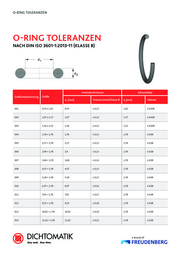
Reduction in Cross-SectionSince elastomers are essentially incompressible materials,if the ID of the O-ring is stretched, the cross-section ofthe O-ring will decrease. The following tables give theO-ring cross-sections that result from ID stretch. The newcross-section should be used for all compression andAS568SeriesOriginal Cross-Sectionin Inchesgland fill calculations for piston-type and externalpressure face seals.The impact of OD interference on the O-ring cross-sectionvaries and does not typically require design considerations.Reduced Cross-Section at% ID Stretch (inches)1%2%3%4%5%- 0XX0.070 in.069.069.068.068.068-1XX0.103 in.102.101.100.100.100-2XX0.139 in.138.137.136.135.134-3XX0.210 in.208.206.205.204.203-4XX0.275 in.272.270.268.267.266AS568SeriesOriginal Cross-Sectionin MillimetersReduced Cross-Section at% ID Stretch (millimeters)1%2%3%4%5%-0XX1.78 mm1.761.751.741.731.72-1XX2.62 mm2.592.572.562.552.53-2XX3.53 mm3.493.473.443.433.41-3XX5.33 mm5.285.245.205.185.15-4XX6.99 mm6.926.876.826.796.75Compression SqueezeCompression squeeze is the difference between the originalO-ring cross-section (CS) and the gland height (H). It isexpressed in either inches or mm.Compression SqueezeCompression SqueezeCalculationCompression Squeeze CS – HRecommended Minimum ValueCSHCompression Squeeze 0.005 inch (0.1 mm)3
Compression RatioThe compression ratio is the ratio between compressionsqueeze and the uncompressed O-ring cross-section.Compression ratio is typically expressed as a percentage.Recommended ValueCalculationCompression Ratio (%) Compression SqueezeCSx 100Piston- or Rod-Type SealMinimum: 5%Target: 20%Maximum: 30%Face-Type SealMinimum: 10%Maximum: 35%Target: 25%Gland FillGland fill is the percentage of the gland that isoccupied by the O-ring. It is calculated by dividingO-Ring Cross-Section AreaO-Ring CSA π x ( CS22)the cross-sectional area (CSA) of the O-ring by thecross-sectional area of the gland.Gland Cross-Section AreaGland FillGland CSA H x W*Gland Fill (%) O-Ring CSAGland CSAx 100WO-RingCSACSHGlandCSA* Effect of gland angle not addressedThe following target gland fill recommendations take intoaccount several hardware and O-ring-related factorsincluding but not limited to thermal expansion, volumeswell due to fluid exposure, and the effect of tolerancestack-ups. A gland fill as low as 50% and as high as90% is acceptable, but it is recommended that thetargets shown below be adhered to whenever possible.Recommended ValuesTarget Minimum: 65%4Target: 75%Target Maximum: 85%
Extrusion GapExtrusion is a concern for radial seals where there is agap between the piston and the bore for a piston-typeseal or between the rod and the bore for a rod-typeseal. It is not typically a concern for face seals where themetal parts to be sealed are in contact line-to-line. Theissue is that at higher pressures and especially for softerO-ring elastomers, the O-ring can be forced by thepressure into the small gap between the piston or rodand the bore. Unless the hardware can ensure the boreand the piston or rod remain concentric, we have toassume that all of the gap possible can shift to oneside (see diagram below).Piston-Type SealRod-Type SealExtrusion Gap Bore – PistonExtrusion Gap Bore – RodExtrusionConcentricity and Diametric ClearanceMaximum Possible Extrusion GapExtrusionGapHighPressureMaximum Recommended Extrusion Gap in Inches (mm)Pressure Elastomer Hardness(PSI)(Durometer)60708090500.010 (.25).015 (.38).020 (.51).025 (.64)750.005 (.13).011 (.28).016 (.41).023 (.58)1000.002 (.05).008 (.20).012 (.30).018 (.46)1250.001 (.02).004 (.10).009 (.23).015 (.38)1500Consult Simrit.002 (.05).007 (.18).012 (.30)For pressures greater than 1500 psi consult Simrit.5
Other Groove DetailsIn addition to proper compression and gland fill, aproperly designed and machined gland is essential for agood O-ring seal. The tables at the right and the diagrambelow provide the recommended gland design parameters. In addition, the gland surfaces must be free from allmachining irregularities, and the gland edges should besmooth and true and free of nicks, scratches, and burrs.Groove Detail DiagramSealingSurfaceWallAngleDetailInchmmWall Angle0 to 5 0 to 5 Break Edge.005 to .010.13 to .25Static SealingSurface Finish32 µinchmaximum0.8 µmmaximumStatic ContainSurface Finish64 µinchmaximum1.6 µmmaximumRadiusAS568SeriesRadiusSealing 3XX.020.035.51.89-4XX.020.035.51.89Break EdgeContaining SurfaceSee table belowInstallation AidsA perfectly designed O-ring seal is of little use if theO-ring is damaged during installation. To preventinstallation damage for piston-type and rod-type seals,we recommend a 15 chamfer on the bore or rod. TheInstallation Chamfer Length6chamfer must be long enough to ensure that the O-ringsees only the chamfer when it is installed. Face-typeseals do not require design considerations beyond thegroove detail recommendations offered above.AS568SeriesO-Ring CSInchesmmChamfer 756.99.2837.20
Properties of Commonly Used ElastomersMaterial NameASTM D1418 DesignationSimriz BlackPurpleBlackRedWhiteBlueTypical ColorsOPERATING TEMPERATURE RANGELow Temperature–20 C–4 F–20 C–4 F–10 C 14 F–40 C–40 F–55 C–67 F–50 C–58 F–75 C–103 F–65 C–85 FHigh Temperature300 C572 F200 C392 F200 C392 F250 C482 F150 C302 F120 C248 F230 C446 F180 C356 FAbrasion Resistance32221244Permeation Resistance22212244Compression Set Resistance22212111Tear 1424Aromatic 44Ketone13441444Water11111111Steam ( 149 C/300 F)12221434Steam ( 149 C/300 F)23344444PHYSICAL PROPERTIESCHEMICAL COMPATIBILITYInorganicOrganicMaterial Rating: 1—Little or no effect (volume change 10%)2—Possible loss of physical properties (volume change 10–20%)3—Noticeable change (volume change 20–40%)4—Excessive change (volume change 40%)0—Insufficient information7
Elastomer MaterialsSimriz PerfluoroelastomerStandard FluoroelastomersDesignation: FFKMDesignation: FKMDescription: Excellent resistance to all chemicals.Excellent outgassing performance in vacuum environments.Description: Excellent resistance to petroleum productsand solvents. Very good high-temperature performance.Fluorocarbon elastomers make up the most widely usedseals in the semiconductor industry.Limitations: Avoid low-molecular-weight, fully halogenatedfluids and molten alkali metals. Strong oxidizing acidsmay cause some swelling. Poor compression set may notbe suitable for some applications. Helium permeability isslightly higher than fluoroelastomer compounds. SpecificSimriz compounds provide better low-temperatureperformance and amine resistance.Temperature Range: –20 to 300 C (–4 to 572 F)Limitations: Avoid polar solvents, amines, anhydrousammonia, SKYDROL, hydrazine, and hot acids.Temperature Range: –40 to 200 C (–40 to 392 F)Hydrocarbon Elastomers—Ethylene-PropyleneDesignation: EP, EPDMHighly Fluorinated FluoroelastomersDesignation: ETP (Viton )Description: Excellent resistance to most chemicals. Theperformance of these products is greater than traditionalfluoroelastomers.Limitations: Contamination performance is somewhatless than Simriz perfluoroelastomer. Avoid service instrong bases or amines.Description: Excellent resistance to water, steam, andpolar solvents, as well as ozone and sunlight. Alsoresistant to alcohols, glycol engine coolants, andSKYDROL (phosphate ester hydraulic fluid). Divided intosulphur-cured and peroxide-cured types. Peroxide-curedcompounds are suitable for higher temperatures andhave much lower compression sets.Limitations: Avoid non-polar solvents, petroleum oils,and aromatic fuels.Temperature Range: –20 to 200 C (–4 to 392 F)Temperature Range: –55 to 150 C (–67 to 302 F)Tetrafluoroethylene/Propylene ElastomersHydrocarbon Elastomers—NitrileDesignation: TFE/P (Aflas )Designation: NBR, XNBR, HNBRDescription: Fluorocarbon elastomer noted for exceptionalthermal and chemical resistance. Excellent resistance toacids, bases, water, and amines. Widely used in oil fields.Description: Very commonly used for O-rings because ofits good mechanical properties and low cost. StandardNitrile is also known as Buna-N. Excellent resistance topetroleum-based oils and fuels, water and alcohols.Nitrile also has good resistance to acids and bases,except those with a strong oxidizing effect. HNBR isobtained by partially or fully hydrogenating NBR leadingto considerable improvement of the resistance to heat,ozone, and aging.Limitations: Avoid polar solvents and aromatic fuels.Compression set performance may be too high for someapplications.Temperature Range: –10 to 200 C (14 to 400 F)Limitations: Avoid highly polar solvents (Acetone, MEK,etc.) and direct exposure to ozone and sunlight.Temperature Range: –55 to 120 C (–65 to 248 F)8Viton is a registered trademarks of DuPont.Aflas is a registered trademark of Asahi Glass Co.
Elastomer Materials—continuedSilicone Elastomers—SiliconePerfluoroetherDesignation: MQ, PMQ, VMQ, PVMQDesignation: FFODescription: Excellent material for static service at extreme(hot or cold) temperatures. Outstanding flex and fatiguelife. Very good for ozone and UV radiation service aswell as for resistance to fungal and biological attack.Description: Combines low-temperature flexibility, fuelresistance, oil resistance, high-temperature stability, andphosphate ester fluid resistance. Excellent performancein jet fuel, piston and jet engine lubricants, and all typesof aircraft hydraulic systems.Limitations: Avoid chlorinated solvents, aliphatic andaromatic hydrocarbons and petroleum oils. Siliconesare generally very permeable to gases and have poorphysical strength and abrasion resistance.Limitations: Avoid ketone solvents.Temperature Range: –65 to 200 C (–85 F to 392 F)Temperature Range: –115 to 232 C (–175 to 450 F)Fluorosilicone Elastomers—FluorosiliconeDesignation: FVMQDescription: Combines excellent low-temperature performance of silicone with improved chemical resistance.Very good resistance to military and aerospace fuels.Excellent performance in oxygen plasma environments.Limitations: Avoid polar solvents, hydrocarbon fluidsand phosphate ester brake fluids. Susceptible to hydrolysis by acids and bases. Limited abrasion resistance.Tempe
ASTM D1418 Designation FFKM ETP TFE/P FKM EPDM NBR VMQ FVMQ Typical Colors Black Black Black Black Black Black Red Blue White White White Purple White Clear Brown Green OPERATING TEMPERATURE RANGE Low Temperature –20 C –20 C –10 C –40 C –55 C –50 C –75 C –65 C –4 F –4 F 14 F –40 F –67 F –58 F –103 F –85 F High Temperature 300 C 200 C 200 C 250 .