Transcription
Powerware Energy Management System (EMS)Upgrade Kit (208/120V, 380/220V, 400/230V, 415/240V)User’s Guide
Requesting a Declaration of ConformityUnits that are labeled with a CE mark comply with the following harmonized standards and EU directives:SHarmonized Standard: IEC 61010 1:2001 02SEU Directives:2006/95/EC, Council Directive on equipment designed for use within certain voltage limits2004/108/EC, Council Directive relating to electromagnetic compatibilityThe EC Declaration of Conformity is available upon request for products with a CE mark. For copies of the ECDeclaration of Conformity, contact:Eaton Power Quality OyKoskelontie 13FIN 02920 EspooFinlandPhone: 358 9 452 661Fax: 358 9 452 665 68Eaton, Powerware, Power Xpert, and X Slot are registered trademarks of Eaton Corporation or its subsidiaries andaffiliates. HyperTerminal is a registered trademark of Hilgraeve. Kirk is a registered trademark of the Kirk KeyInterlock Company. Microsoft and Windows are registered trademarks of Microsoft Corporation in the United Statesand/or other countries. Modbus is a registered trademark of Schneider Electric. National Electrical Code and NEC areregistered trademarks of National Fire Protection Association, Inc. Phillips is a registered trademark of Phillips ScrewCompany. All other trademarks are property of their respective companies.ECopyright 2008 Eaton Corporation, Raleigh, NC, USA. All rights reserved. No part of this document may bereproduced in any way without the express written approval of Eaton Corporation.
Special SymbolsThe following are examples of symbols used on the UPS or accessories to alert you to importantinformation:RISK OF ELECTRIC SHOCK Observe the warning associated with the risk of electric shocksymbol.CAUTION: REFER TO OPERATOR’S MANUAL Refer to your operator’s manual for additionalinformation, such as important operating and maintenance instructions.This symbol indicates that you should not discard waste electrical or electronic equipment (WEEE) inthe trash. For proper disposal, contact your local recycling/reuse or hazardous waste center.Three phase alternating currentPROTECTIVE CONDUCTOR TERMINALDo not apply around or remove from hazardous live conductors.
Table of Contents123Introduction . . . . . . . . . . . . . . . . . . . . . . . . . . . . . . . . . . . . . . . . . . . . . . . . . . . . . . . . .1Safety Warnings . . . . . . . . . . . . . . . . . . . . . . . . . . . . . . . . . . . . . . . . . . . . . . . . . . . . . . . . . . . . . . . . . . . . .3Installation . . . . . . . . . . . . . . . . . . . . . . . . . . . . . . . . . . . . . . . . . . . . . . . . . . . . . . . . . .7Inspecting the Equipment . . . . . . . . . . . . . . . . . . . . . . . . . . . . . . . . . . . . . . . . . . . . . . . . . . . . . . . . . . . . . . .Unpacking the Cabinet . . . . . . . . . . . . . . . . . . . . . . . . . . . . . . . . . . . . . . . . . . . . . . . . . . . . . . . . . . . . . . . . .Checking the Parts List . . . . . . . . . . . . . . . . . . . . . . . . . . . . . . . . . . . . . . . . . . . . . . . . . . . . . . . . . . . . . . . . .Tools Required . . . . . . . . . . . . . . . . . . . . . . . . . . . . . . . . . . . . . . . . . . . . . . . . . . . . . . . . . . . . . . . . . . . . . .Installing the Hardware . . . . . . . . . . . . . . . . . . . . . . . . . . . . . . . . . . . . . . . . . . . . . . . . . . . . . . . . . . . . . . . .Electrical Connections . . . . . . . . . . . . . . . . . . . . . . . . . . . . . . . . . . . . . . . . . . . . . . . . . . . . . . . . . . . . . . . . .Initial Configuration . . . . . . . . . . . . . . . . . . . . . . . . . . . . . . . . . . . . . . . . . . . . . . . . . . . . . . . . . . . . . . . . . . .Installing the Software Configuration Tool . . . . . . . . . . . . . . . . . . . . . . . . . . . . . . . . . . . . . . . . . . . . . . . .Initial System Configuration . . . . . . . . . . . . . . . . . . . . . . . . . . . . . . . . . . . . . . . . . . . . . . . . . . . . . . . . . .Initial Panel and Breaker Configuration (Using the Software Configuration Tool) . . . . . . . . . . . . . . . . . . . . . .Initial Panel and Breaker Configuration (Using the Display) . . . . . . . . . . . . . . . . . . . . . . . . . . . . . . . . . . . . .Advanced Metering Installation . . . . . . . . . . . . . . . . . . . . . . . . . . . . . . . . . . . . . . . . . . . . . . . . . . . . . . . . . .77891013252526313436Operation . . . . . . . . . . . . . . . . . . . . . . . . . . . . . . . . . . . . . . . . . . . . . . . . . . . . . . . . . . .37Reset Function . . . . . . . . . . . . . . . . . . . . . . . . . . . . . . . . . . . . . . . . . . . . . . . . . . . . . . . . . . . . . . . . . . . . . .Breaker Numbering . . . . . . . . . . . . . . . . . . . . . . . . . . . . . . . . . . . . . . . . . . . . . . . . . . . . . . . . . . . . . . . . . . .Control Panel Functions . . . . . . . . . . . . . . . . . . . . . . . . . . . . . . . . . . . . . . . . . . . . . . . . . . . . . . . . . . . . . . . .Display Functions . . . . . . . . . . . . . . . . . . . . . . . . . . . . . . . . . . . . . . . . . . . . . . . . . . . . . . . . . . . . . . . . . .Menu Map . . . . . . . . . . . . . . . . . . . . . . . . . . . . . . . . . . . . . . . . . . . . . . . . . . . . . . . . . . . . . . . . . . . . . .Setup Options . . . . . . . . . . . . . . . . . . . . . . . . . . . . . . . . . . . . . . . . . . . . . . . . . . . . . . . . . . . . . . . . . . . .Control Panel Configuration . . . . . . . . . . . . . . . . . . . . . . . . . . . . . . . . . . . . . . . . . . . . . . . . . . . . . . . . . . . . .Accessing Configuration . . . . . . . . . . . . . . . . . . . . . . . . . . . . . . . . . . . . . . . . . . . . . . . . . . . . . . . . . . . . .Configuring Panels Containing Branch Circuit Breakers . . . . . . . . . . . . . . . . . . . . . . . . . . . . . . . . . . . . . . .Configuring Panels Containing Subfeed Breakers . . . . . . . . . . . . . . . . . . . . . . . . . . . . . . . . . . . . . . . . . . . .Configuring Branch Circuit Breakers . . . . . . . . . . . . . . . . . . . . . . . . . . . . . . . . . . . . . . . . . . . . . . . . . . . . .Viewing Panel Meters . . . . . . . . . . . . . . . . . . . . . . . . . . . . . . . . . . . . . . . . . . . . . . . . . . . . . . . . . . . . . . . . .Viewing Breaker Meters . . . . . . . . . . . . . . . . . . . . . . . . . . . . . . . . . . . . . . . . . . . . . . . . . . . . . . . . . . . . . . . .37373839404243434344464848EATON Powerware Energy Management System (EMS) Upgrade Kit User’s Guide S 164201724 Rev 1 www.powerware.comi
TABLE OF CONTENTS4Communication . . . . . . . . . . . . . . . . . . . . . . . . . . . . . . . . . . . . . . . . . . . . . . . . . . . . . .49Installing Communication Features . . . . . . . . . . . . . . . . . . . . . . . . . . . . . . . . . . . . . . . . . . . . . . . . . . . . . . . .Communication Options . . . . . . . . . . . . . . . . . . . . . . . . . . . . . . . . . . . . . . . . . . . . . . . . . . . . . . . . . . . . . . . .Serial Port (Service) . . . . . . . . . . . . . . . . . . . . . . . . . . . . . . . . . . . . . . . . . . . . . . . . . . . . . . . . . . . . . . . .X Slot Card . . . . . . . . . . . . . . . . . . . . . . . . . . . . . . . . . . . . . . . . . . . . . . . . . . . . . . . . . . . . . . . . . . . . . .Control Terminals . . . . . . . . . . . . . . . . . . . . . . . . . . . . . . . . . . . . . . . . . . . . . . . . . . . . . . . . . . . . . . . . . . . .Relay Output Contacts (Alarm Relay) . . . . . . . . . . . . . . . . . . . . . . . . . . . . . . . . . . . . . . . . . . . . . . . . . . . .Programmable Signal Inputs (Building Alarms) . . . . . . . . . . . . . . . . . . . . . . . . . . . . . . . . . . . . . . . . . . . . .50505051525353Maintenance . . . . . . . . . . . . . . . . . . . . . . . . . . . . . . . . . . . . . . . . . . . . . . . . . . . . . . . .55Recycling the Used Equipment . . . . . . . . . . . . . . . . . . . . . . . . . . . . . . . . . . . . . . . . . . . . . . . . . . . . . . . . . . .Updating the Firmware . . . . . . . . . . . . . . . . . . . . . . . . . . . . . . . . . . . . . . . . . . . . . . . . . . . . . . . . . . . . . . . . .Replacing the Power Xpert Gateway Series 1000 Card . . . . . . . . . . . . . . . . . . . . . . . . . . . . . . . . . . . . . . . . . .Rewiring and Reconfiguring the Installation . . . . . . . . . . . . . . . . . . . . . . . . . . . . . . . . . . . . . . . . . . . . . . . . . .555555566Specifications . . . . . . . . . . . . . . . . . . . . . . . . . . . . . . . . . . . . . . . . . . . . . . . . . . . . . . .577Troubleshooting . . . . . . . . . . . . . . . . . . . . . . . . . . . . . . . . . . . . . . . . . . . . . . . . . . . . . .61Typical Alarms and Conditions . . . . . . . . . . . . . . . . . . . . . . . . . . . . . . . . . . . . . . . . . . . . . . . . . . . . . . . . . . .Service and Support . . . . . . . . . . . . . . . . . . . . . . . . . . . . . . . . . . . . . . . . . . . . . . . . . . . . . . . . . . . . . . . . . . .6161Warranty . . . . . . . . . . . . . . . . . . . . . . . . . . . . . . . . . . . . . . . . . . . . . . . . . . . . . . . . . . .63Limited Factory Warranty . . . . . . . . . . . . . . . . . . . . . . . . . . . . . . . . . . . . . . . . . . . . . . . . . . . . . . . . . . . . . . .6358iiEATON Powerware Energy Management System (EMS) Upgrade Kit User’s Guide S 164201724 Rev 1 www.powerware.com
Chapter 1IntroductionEaton’s Powerware Energy Management System (EMS) Upgrade Kit(EMS UGK) is designed to monitor energy usage of existing powerdistribution panelboards, remote power panels, or power distributionunits. Providing outstanding performance and reliability, the EMS UGK’sunique benefits include the following:S Monitors up to 42 (single panel) or 84 (dual panel) circuits in astandard three phase panelboard. Measures and stores energyparameters for each of the individual monitored circuits, letting youmanage power with greater precision.S Functions in a wide variety of applications supporting various datacenter loads that may require a power distribution monitoringsolution, especially where power needs are changing and backuparchitecture must be scalable.S Can be mounted on a wall with the included mounting bracket andcustomer supplied fasteners appropriate for the type of wall.S Choice of voltage sensing installation: connection to an unoccupiedcircuit breaker using included transition harnesses or connection to anoccupied circuit breaker using included wire taps.S Includes a software tool for easy configuring of settings and options.S All harnesses supplied except for optional external ground.S No preventive maintenance required other than verifying thehardware and wiring are clear of debris. The EMS UGK does notrequire an annual calibration.S Advanced Metering monitoring system, providing communicationoptions such as network connectivity through the Power Xpert Gateway Card installed in the X Slot communication bay.S Intended for continuous duty operation.S Backed by worldwide agency approvals.EATON Powerware Energy Management System (EMS) Upgrade Kit User’s Guide S 164201724 Rev 1 www.powerware.com1
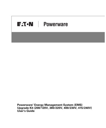
INTRODUCTIONThe following options for the EMS UGK are available:S Single panel (42 circuits) or dual panel (84 circuits)S 208/120V or 380/220V, 400/230V, 415/240V ratingS Liquid crystal display (LCD) for local indication of energy usageS Conduit box for enhanced harness protectionS Main input monitoring (three phases and one neutral rated tomeasure currents up to 400A; up to 100A for input ground)The following accessories for the EMS UGK are available:S Subfeed breaker monitoring, rated to measure currents up to 400AS 100A branch circuit breaker monitoringS Temperature and humidity monitoring with the optionalEnvironmental Monitoring Probe (EMP) that is used with thePower Xpert Gateway Series 1000 Card installed in the EMS UGKThe EMS UGK includes an externally mounted enclosure with anoptional display. Current transformers (CTs) provide branch circuitmonitoring of installed panelboards. Figure 1 shows an exampleinstallation of an EMS UGK.Figure 1. Typical EMS UGK Installation (Dual Panel Shown with Optional Display)2EATON Powerware Energy Management System (EMS) Upgrade Kit User’s Guide S 164201724 Rev 1 www.powerware.com
INTRODUCTIONSafety WarningsIMPORTANT SAFETY INSTRUCTIONSSAVE THESE INSTRUCTIONSThis manual contains important instructions that you should follow during installation andoperation of the EMS UGK. Please read all instructions before operating the equipment andsave this manual for future reference.DANGERThis EMS UGK contains LETHAL VOLTAGES. All repairs and service should be performedby AUTHORIZED SERVICE PERSONNEL ONLY. There are NO USER SERVICEABLEPARTS inside the EMS UGK.CAUTIONS To reduce the risk of fire or electric shock, install this EMS UGK in a temperature andhumidity controlled, indoor environment, free of conductive contaminants. Ambienttemperature must not exceed 40 C (104 F). Do not operate near water or excessivehumidity (95% maximum).S Use the branch circuit breakers to disconnect hazardous voltage from the EMS UGK. Turnoff the breaker before disconnecting the voltage measuring circuit cables, or hazardousvoltage may be present at the exposed end of the cable.S Installation or use of the equipment in a manner not specified by the manufacturer mayimpair the protection provided by the equipment.EATON Powerware Energy Management System (EMS) Upgrade Kit User’s Guide S 164201724 Rev 1 www.powerware.com3
INTRODUCTIONConsignes de sécuritéCONSIGNES DE SÉCURITÉ IMPORTANTESCONSERVER CES INSTRUCTIONSCe manuel contient des instructions importantes que vous êtes invité à suivre lors de touteprocédure d’installation et de fonctionnement de EMS UGK. Veuillez consulter entièrementces instructions avant de faire fonctionner l’équipement et conserver ce manuel afin depouvoir vous y reporter ultérieurement.DANGER!Cet EMS UGK con
INTRODUCTION 2 EATON Powerware Energy Management System (EMS) Upgrade Kit User’s Guide 164201724 Rev 1 www.powerware.com The following options for the EMS UGK are available: Single panel (42 circuits) or dual panel (84 circuits) 208/120V or 380/220V, 400/230V, 415/240V rating