Transcription
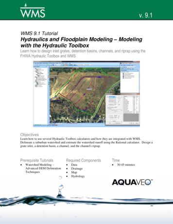
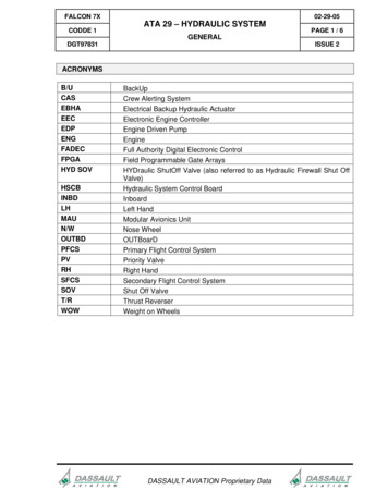
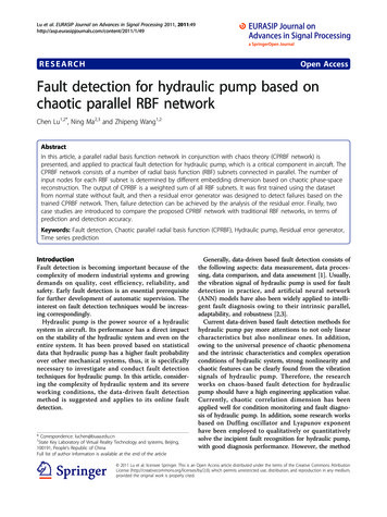
Technical DescriptionDevelopment of Electro-hydraulic Actuators forRobotsThe first industrial robot in Japan (KawasakiUnimate) was hydraulically actuated, but since the late1980s, electric motor actuation has been replacinghydraulic actuation. In recent years, however,humanoid robots, which are increasingly expected tobe used mainly at disaster sites, need to be durable andpowerful, and hydraulic actuation has been recognizedonce again.Kawasaki is developing Hydro Servo Muscle, whichis an electro-hydraulic actuator that is characterized byits high impact resistance and power density and isintended to be applied to the legs of Kaleido, which is ahumanoid robot Kawasaki is developing.In recent years, there are increasing expectations forlife-size humanoid robots, which do various tasks atdisaster sites and in extreme environments in place ofhumans by using tools for humans.thrust motion is required for standing up, and high-speed,low-thrust motion is required for walking.Therefore, actuators for humanoid robots are requiredto have small size and weight, a good balance betweenhigh-speed, low-thrust motion and low-speed, high-thrustmotion, high reliability, and high impact resistance.1 Background3 Overview of actuatorsHydraulic actuation technology has mainly been usedfor construction machinery that requires high power andhigh environment resistance, and electric motor drivetechnology has been used in the robot field where highspeed and high accuracy are required. Recently, however,the trend is to use hydraulic drive for humanoid robots andother robots that require powerful movements in severeenvironments.(1) Development conceptWe decided to develop actuators intended mainly foruse in the legs as shown in Fig. 1 where both high speedand high thrust are required. For electric actuators, there isa risk of damaging the gear reduction mechanism due tounexpected impact during work, but for hydraulicactuators, which have higher impact resistance, it ispossible to provide humanoid robots with a function toavoid damage by using oil compressibility and a highlyresponsive pressure relief mechanism.Introduction2 Humanoid robotsAmid such circumstances, Kawasaki is developinghumanoid robots as other manufacturers are. Currently,Kawasaki’s humanoid robot has a total height of 1.75 m anda weight of 84 kg, and it has 32 degrees of freedom in totalfor all the joints, including the legs and arms, driven byelectric actuators. Achieving the same size as humansrequires pursuing size and weight reduction in each partand eliminating projections that humans do not have toprevent interference in each section. Also, low-speed, high33(2) Equipment configuration and specificationsFigure 2 shows the equipment configuration andhydraulic circuit of the electro-hydraulic actuator. Table 1shows the specifications of the electro-hydraulic actuator.The servo motor, hydraulic pump, valve unit, and hydrauliccylinder have been integrated into one unit, therebyforming a compact construction without piping betweenhydraulic devices. In addition, a closed-circuit configurationhas been adopted that feeds oil to the cylinder according to
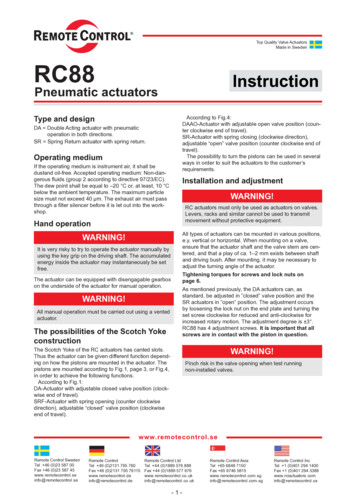
Fig. 1 Applying this technology to the legs of humanoid robot KaleidoHydraulic cylinderValve unitPressure tankRelief valveServo motorPressure tankRelief valvePilot check valveVariable capacityhydraulic pumpPilot checkvalveHydraulic cylinderVariable capacitypumpServo motor(a) Equipment configuration(b) Hydraulic circuitFig. 2 Configuration of electro-hydraulic actuatorTable 1 Specifications of electro-hydraulic actuatorMaximum thrust 〔N〕6, 000Maximum speed〔mm/s〕200Head diameter〔mm〕22Rod diameter〔mm〕8Stroke〔mm〕156Impact resistance functionYesthe servo motor speed.This actuator, like other electric actuators, can be drivenby using a robot controller. By detecting the leg joint anglewith a separate encoder, the servo motor is controlled toposition the cylinder so that the desired angle can beachieved.4 Details of developmentIn order to achieve size and weight reduction of theactuator, a good balance between high-speed, low-thrustmotion and low-speed, high-thrust motion, and highreliability as well as high impact resistance, we developedKawasaki Technical Review No.181May 202034
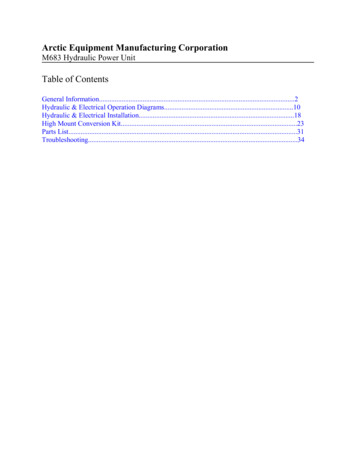
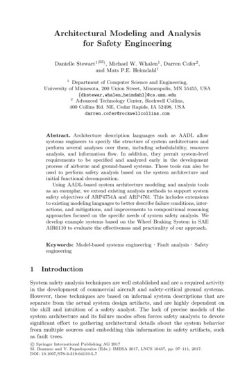
Technical Descriptionthe following technologies and methods.(1) Size and weight reduction( i ) Developing a compact valve unitTo minimize the valve unit size, we set the number ofvalves to the minimum value required to realize therequired functions and developed a new manifoldcontaining specially designed valves and oil passages. Thefollowing parts need to be developed for the valves thatmake up the valve unit shown in Fig. 3.① Relief valveTo release excessive external force that the actuatorhas received immediately and accurately by oil pressure,there is a need to achieve high responsiveness andreduce override characteristics, which cause the reliefpressure to increase as the flow rate increases.② Pilot check valveWhen the actuator retracts, the valve is opened withlow pump discharge pressure to return extra oil fromthe head caused by the difference in cylinder area to thepressure tank. In addition, the pressure loss isminimized to allow oil from the tank to flow smoothlyinto the actuator when the actuator advances.To achieve the above functions and performance, wedeveloped a compact cartridge valve. We reduced thenumber of oil passages in the manifold to a minimumand arranged the valves so that the minimum requiredthickness could be achieved around the oil passages,thereby achieving a manifold size of less than 40 mmsquare, which is the same as the servo motor size. Inaddition, we designed the internal diameter, length, andcrossing shape of oil passages so that the smallestpressure loss could be achieved.(ii) Integrating the valve unit, unit cover, and tank into oneunitCommon hydraulic actuators consist of valves,cylinders, a pump, a tank, and other blocks connected toone another. Integrating these blocks into one uniteliminates the need to seal between blocks and providesenhanced flexibility in the layout of oil passages, therebyachieving further size reduction.Therefore, we integrated the valve unit, cylinder headcover, pump valve cover, and tank connection block intoone unit as shown in Fig. 4, taking the following intoaccount.① Optimizing the oil passages connecting the partsRelief valve40mm40mmPilot check valveRelief valveOil passagePilot check valveFig. 3 Valve unitCylinder head coverValve unitPump valve coverTank connection blockFig. 4 Integration of components35
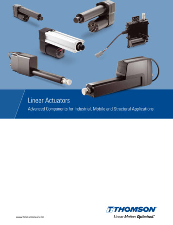
The parts were connected linearly with the valve oilchamber, thereby achieving an efficient piping layout.② Rethinking the tank volumeTanks designed in conformity with general industrialmachinery standards are too large. For application torobots, we set the tank volume to 1.1 times theminimum required volume rather than 4.2 times.With these efforts, the distance between the actuatormounting position and pump mounting position wassignificantly reduced.(iii) Integrating the hydraulic pump and servo motor intoone unitInitially, the hydraulic pump and the servo motor, whichdrives the hydraulic pump, were arranged coaxially witheach other, and the shafts were spline-coupled. However,while using belts and gears reduces drive transmissionloss, it leads to size increase and causes insufficientstrength in the joints. To solve this problem, we integratedthe drive shafts of the pump and motor into one unit asshown in Fig. 5. For this integration, we optimized theflange shape for connecting the pump and motor, oil seals,and bearings.For the bearings used for the pump and motor, weused the same bearing in the middle between the pumpand bearing, thereby reducing the number of parts andsize. In addition, to prevent stress from being generated inthe shaft, we adopted a slide bearing on the pump-sideshaft end.(2) Achieving a good balance between high-speed,low-thrust motion and low-speed, high-thrustmotionTo achieve a good balance between high-speed, lowthrust motion and low-speed, high-thrust motion, which isrequired for humanoid robots, we needed a variablecapacity hydraulic pump. Based on the swash plate pistonpump technology we have accumulated in makingconstruction machinery and industrial machinery, wedeveloped a variable capacity swash plate piston pumpwith displacement from 0.75 cm3 to 1.5 cm3 as shown inFig. 6.This pump can supply high-pressure hydraulic oil to theactuator without causing an overload in the servo motor byoptimally controlling the pump capacity according to theload pressure of the actuator. In addition, this pump has amechanism to control the pump capacity in a steplessfashion according to the load pressure by optimallybalancing the oil pressure generated on the piston and thespring load holding the slash plate angle. This mechanismnot only efficiently converts the output from the servoPumpMotorFig. 5 Integration of shaftInclined return springSwash plateFig. 6 Swash plate type variable displacement axial piston pumpKawasaki Technical Review No.181May 202036
Technical Descriptionmotor to hydraulic energy, but also provides a simplerswash plate drive mechanism without a solenoid switchingvalve, thereby contributing to size and weight reduction.The conventional system uses a solenoid switchingvalve to adjust the capacity in two steps; therefore, in orderto allow the pump to operate continuously without causingan overload in the servo motor, there is a need to switchthe capacity from high to low when the pressure rises,wasting some of the power. The pump we developed thistime adjusts the capacity in a stepless fashion when thepressure rises and converts the power from the servomotor efficiently to hydraulic energy, thereby achievinghigh-speed, high-thrust motion in the entire pressure rangewith less power.(3) Improving reliability( i ) Vibration damping control of the hydraulic cylinderFigure 7 shows a block diagram representing positioncontrol in the servo motor control system of this actuator.The actual position data is fed back with an encoder, andSpeed feedforward control KP㻌 PositionPosition㻌command - SpeedSpeedcommand deviation-deviation㻌 Positionproportional gainActual speedS㻌ActualpositionFig. 7 Block diagram of position controlSpeed〔mm/s〕20Before the control is appliedAfter the control is applied151050-50246Time〔s〕Fig. 8 Effect of vibration suppression controlPackingDust packingRisk of hydraulicoil leakage作動油漏れのリスクDust packingPrevention of hydraulic oil leakageLarge friction resistance摩擦抵抗大Brass bush(a) Before modificationSpecial rod sealReduction of friction resistancePTFE bush(b) After modificationFig. 9 Modification of cylinder bearing rodPrevention ofresidual pressureDeteriorated sealingperformance dueto residual pressurePacking(a) Before modification(b) After modificationFig. 10 Modification of cylinder bearing piston37PTFE bearingPacking withlow sliding friction
speed commands are given to the motor based on thedeviation between the actual position and positioncommand. Because the position proportional gain isadjusted so that the responsiveness can be maintainedeven at high loads or speeds, the position proportional gainbecomes too large at low loads or speeds, causingpersistent vibration or hunting. This is attributable to adelay in the actuation of the hydraulic cylinder after theservo motor is activated and oil is discharged.To prevent this, we developed a function to detect alow load or speed based on the motor current and motorspeed and appropriately adjust the position proportionalgain and gain in speed feedforward control. Figure 8shows the waveforms of the hydraulic cylinder speed atlow load and speed before and after this control wasapplied. As shown in the figure, continuous vibration hasbeen reduced significantly.(ii) Modifying the cylinder bearingWe modified the cylinder bearing rod and piston. Therod initially consisted of a brass bush, seals, and dustpacking, but with this configuration, there is a risk ofhydraulic oil leaking if an external impact load is applied inthe axial direction of the rod. In addition, the brass bushhas a large frictional resistance. Therefore, we adopted aspecially designed rod seal with enhanced pressureresistance as shown in Fig. 9 and changed the bushmaterial to PTFE, thereby eliminating the risk and problem.The piston was initially structured so that it wassupported and sealed by the piston seals. Depending onthe operating conditions, however, there was a risk thathydraulic oil may intrude between two seals, resulting indeteriorated sealing performance due to residual pressure.To solve this problem, one PTFE bearing and one pistonseal were arranged next to each other as shown in Fig. 10.Professional Engineer(Electrical & Electronics Engineering)Hideki TanakaAdvanced Technology Department,Engineering Group,Precision Machinery Business Division,Precision Machinery & Robot CompanySatoshi YoritaAdvanced Technology Department,Engineering Group,Precision Machinery Business Division,Precision Machinery & Robot CompanyMariko OgataAdvanced Technology Department,Engineering Group,Precision Machinery Business Division,Precision Machinery & Robot CompanyIsamu YoshimuraComponents Engineering Department 1,Engineering Group,Precision Machinery Business Division,Precision Machinery & Robot CompanyTomohide HattoriSystems Engineering Department,Engineering Group,Precision Machinery Business Division,Precision Machinery & Robot CompanyTadashi AnadaAdvanced Technology Department,Engineering Group,Precision Machinery Business Division,Precision Machinery & Robot CompanyShinji NaritaConclusionMounting electro-hydraulic actuators on humanoidrobots is the challenge we are facing to achieve synergybetween the hydraulic technologies and robot technologiesKawasaki has. Not only can this actuator be used forrobots, but for autonomous mobile systems, productionlines, and industrial machinery. As public relations efforts,we exhibited this actuator at IFPEX2017 and IREX2017 as areference exhibit and registered its trademark as HydroServo Muscle.Some people say that hydraulic technology is alreadyAdvanced Technology Department,Engineering Group,Precision Machinery Business Division,Precision Machinery & Robot Companymature. However, we will be pursuing size and weightreduction and user-friendliness to realize a system whereboth hydraulic technology and electric technology can beused, thereby creating something new.Kawasaki Technical Review No.181May 202038
the servo motor speed. This actuator, like other electric actuators, can be driven by using a robot controller. By detecting the leg joint angle with a separate encoder, the servo motor is controlled to position the cylinder so that the desired angle can be achieved. 4 Details of development In order to achieve size and weight reduction of the