Transcription
HP ProCurve 1410 Switch SeriesInstallation and Getting Started GuideHP ProCurve 1410-8G Switch (J9559A)HP ProCurve 1410-16G Switch (J9560A)HP ProCurve 1410-24G Switch (J9561A)
HP ProCurve 1410 Switch SeriesInstallation and Getting Started Guide
Copyright 2010 Hewlett-Packard DevelopmentCompany, L.P.Publication Number5998-0347April 2010HEWLETT-PACKARD COMPANY MAKES NO WARRANTYOF ANY KIND WITH REGARD TO THIS MATERIAL,INCLUDING, BUT NOT LIMITED TO, THE IMPLIEDWARRANTIES OF MERCHANTABILITY AND FITNESSFOR A PARTICULAR PURPOSE. Hewlett-Packard shall notbe liable for errors contained herein or for incidental orconsequential damages in connection with the furnishing,performance, or use of this material.The information contained herein is subject to changewithout notice. The only warranties for HP products andservices are set forth in the express warranty statementsaccompanying such products and services. Nothing hereinshould be construed as constituting an additional warranty.HP shall not be liable for technical or editorial errors oromissions contained herein.Applicable ProductsHP ProCurve 1410-8G SwitchHP ProCurve 1410-16G SwitchHP ProCurve 1410-24G ckard assumes no responsibility for the use orreliability of its software on equipment that is not furnishedby Hewlett-Packard.WarrantySee the Software License, Warranty and Support bookletincluded with the product.A copy of the specific warranty terms applicable to yourHewlett-Packard products and replacement parts can beobtained from your HP Sales and Service Office orauthorized dealer.SafetyBefore installing and operating these products, please readthe “Installation Precautions” in chapter 2, “Installing theSwitch”, and the safety statements in appendix B, “Safetyand EMC Regulatory Statements”.Hewlett-Packard Company8000 Foothills Boulevard, m/s 5551Roseville, California 95747-5551www.hp.com/go/procurve
ContentsContents1 Introducing the SwitchFront of the Switch . . . . . . . . . . . . . . . . . . . . . . . . . . . . . . . . . . . . . . . . . . . . . . 1-3Network Ports . . . . . . . . . . . . . . . . . . . . . . . . . . . . . . . . . . . . . . . . . . . . . . 1-4LEDs . . . . . . . . . . . . . . . . . . . . . . . . . . . . . . . . . . . . . . . . . . . . . . . . . . . . . . 1-4Back of the Switch . . . . . . . . . . . . . . . . . . . . . . . . . . . . . . . . . . . . . . . . . . . . . . 1-5Power Connector . . . . . . . . . . . . . . . . . . . . . . . . . . . . . . . . . . . . . . . . . . . 1-5Switch Features . . . . . . . . . . . . . . . . . . . . . . . . . . . . . . . . . . . . . . . . . . . . . . . . 1-62 Installing the SwitchIncluded Parts . . . . . . . . . . . . . . . . . . . . . . . . . . . . . . . . . . . . . . . . . . . . . . . . . . 2-1Installation Precautions . . . . . . . . . . . . . . . . . . . . . . . . . . . . . . . . . . . . . . 2-3Installation Procedures . . . . . . . . . . . . . . . . . . . . . . . . . . . . . . . . . . . . . . . . . . 2-41. Prepare the Installation Site . . . . . . . . . . . . . . . . . . . . . . . . . . . . . . . . 2-52. Verify the Switch Passes Self Test . . . . . . . . . . . . . . . . . . . . . . . . . . . 2-6LED Behavior . . . . . . . . . . . . . . . . . . . . . . . . . . . . . . . . . . . . . . . . . . . 2-83. Mount the Switch . . . . . . . . . . . . . . . . . . . . . . . . . . . . . . . . . . . . . . . . . 2-9Rack or Cabinet Mounting . . . . . . . . . . . . . . . . . . . . . . . . . . . . . . . . 2-9Rack Mounting the Switch . . . . . . . . . . . . . . . . . . . . . . . . . . . . . . . 2-10Wall or Under-Table Mounting . . . . . . . . . . . . . . . . . . . . . . . . . . . . 2-13Horizontal Surface Mounting . . . . . . . . . . . . . . . . . . . . . . . . . . . . . 2-14Using a Kensington Security Cable . . . . . . . . . . . . . . . . . . . . . . . . 2-154. Connect the Switch to a Power Source . . . . . . . . . . . . . . . . . . . . . . 2-155. Connect the Network Cables . . . . . . . . . . . . . . . . . . . . . . . . . . . . . . . 2-18Using the RJ-45 Connectors . . . . . . . . . . . . . . . . . . . . . . . . . . . . . . 2-186. Installing or Removing mini-GBICs . . . . . . . . . . . . . . . . . . . . . . . . .Installing the mini-GBICs: . . . . . . . . . . . . . . . . . . . . . . . . . . . . . . . .Removing the mini-GBICs . . . . . . . . . . . . . . . . . . . . . . . . . . . . . . . .Connecting Cables to mini-GBICs . . . . . . . . . . . . . . . . . . . . . . . . .2-192-192-202-20Sample Network Topologies . . . . . . . . . . . . . . . . . . . . . . . . . . . . . . . . . . . . . 2-22iii
ContentsAs a Desktop Switch . . . . . . . . . . . . . . . . . . . . . . . . . . . . . . . . . . . . . . . . 2-22As a Segment Switch . . . . . . . . . . . . . . . . . . . . . . . . . . . . . . . . . . . . . . . . 2-233 TroubleshootingBasic Troubleshooting Tips . . . . . . . . . . . . . . . . . . . . . . . . . . . . . . . . . . . . . . 3-1Diagnosing with the LEDs . . . . . . . . . . . . . . . . . . . . . . . . . . . . . . . . . . . . . . . . 3-3LED patterns for General Switch Troubleshooting . . . . . . . . . . . . . . . 3-3Hardware Diagnostic Tests . . . . . . . . . . . . . . . . . . . . . . . . . . . . . . . . . . . . . . . 3-5Testing the Switch by Resetting It . . . . . . . . . . . . . . . . . . . . . . . . . . . . . 3-5Testing Twisted-Pair Cabling . . . . . . . . . . . . . . . . . . . . . . . . . . . . . . . . . . 3-5Testing End-to-End Network Communications . . . . . . . . . . . . . . . . . . 3-5HP Customer Support Services . . . . . . . . . . . . . . . . . . . . . . . . . . . . . . . . . . . 3-6Before Calling Support . . . . . . . . . . . . . . . . . . . . . . . . . . . . . . . . . . . . . . . 3-6A SpecificationsSwitch Specifications . . . . . . . . . . . . . . . . . . . . . . . . . . . . . . . . . . . . . . . . . . . A-1Physical . . . . . . . . . . . . . . . . . . . . . . . . . . . . . . . . . . . . . . . . . . . . . . . . . . . A-1Electrical . . . . . . . . . . . . . . . . . . . . . . . . . . . . . . . . . . . . . . . . . . . . . . . . . A-1Environmental . . . . . . . . . . . . . . . . . . . . . . . . . . . . . . . . . . . . . . . . . . . . . A-2BTU Ratings . . . . . . . . . . . . . . . . . . . . . . . . . . . . . . . . . . . . . . . . . . . A-2Acoustics . . . . . . . . . . . . . . . . . . . . . . . . . . . . . . . . . . . . . . . . . . . . . . . . . A-2Safety . . . . . . . . . . . . . . . . . . . . . . . . . . . . . . . . . . . . . . . . . . . . . . . . . . . . A-2Standards . . . . . . . . . . . . . . . . . . . . . . . . . . . . . . . . . . . . . . . . . . . . . . . . . . . . . A-3Cabling and Technology Information Specifications . . . . . . . . . . . . . . . . A-4Technology Distance Specifications . . . . . . . . . . . . . . . . . . . . . . . . . . . A-5Mode Conditioning Patch Cord . . . . . . . . . . . . . . . . . . . . . . . . . . . . . . . . . . A-6Installing the Patch Cord . . . . . . . . . . . . . . . . . . . . . . . . . . . . . . . . . . . . A-6Twisted-Pair Cable/Connector Pin-Outs . . . . . . . . . . . . . . . . . . . . . . . . . . . A-8Straight-through Twisted-Pair Cable for10 Mbps or 100 Mbps Network Connections . . . . . . . . . . . . . . . . . . . A-10Cable Diagram . . . . . . . . . . . . . . . . . . . . . . . . . . . . . . . . . . . . . . . . A-10Pin Assignments . . . . . . . . . . . . . . . . . . . . . . . . . . . . . . . . . . . . . . . A-10iv
ContentsCrossover Twisted-Pair Cable for10 Mbps or 100 Mbps Network Connection . . . . . . . . . . . . . . . . . . . . A-11Cable Diagram . . . . . . . . . . . . . . . . . . . . . . . . . . . . . . . . . . . . . . . . A-11Pin Assignments . . . . . . . . . . . . . . . . . . . . . . . . . . . . . . . . . . . . . . . A-11Straight-Through Twisted-Pair Cable for1000 Mbps Network Connections . . . . . . . . . . . . . . . . . . . . . . . . . . . . A-12Cable Diagram . . . . . . . . . . . . . . . . . . . . . . . . . . . . . . . . . . . . . . . . A-12Pin Assignments . . . . . . . . . . . . . . . . . . . . . . . . . . . . . . . . . . . . . . . A-12B Safety and EMC Regulatory StatementsSafety Information . . . . . . . . . . . . . . . . . . . . . . . . . . . . . . . . . . . . . . . . . . . . . B-1EMC Regulatory Statements . . . . . . . . . . . . . . . . . . . . . . . . . . . . . . . . . . . . . B-8U.S.A. . . . . . . . . . . . . . . . . . . . . . . . . . . . . . . . . . . . . . . . . . . . . . . . . . . . . B-8Canada . . . . . . . . . . . . . . . . . . . . . . . . . . . . . . . . . . . . . . . . . . . . . . . . . . . B-8Australia/New Zealand . . . . . . . . . . . . . . . . . . . . . . . . . . . . . . . . . . . . . . B-8Japan . . . . . . . . . . . . . . . . . . . . . . . . . . . . . . . . . . . . . . . . . . . . . . . . . . . . . B-8Korea . . . . . . . . . . . . . . . . . . . . . . . . . . . . . . . . . . . . . . . . . . . . . . . . . . . . . B-9Taiwan . . . . . . . . . . . . . . . . . . . . . . . . . . . . . . . . . . . . . . . . . . . . . . . . . . . B-9European Community . . . . . . . . . . . . . . . . . . . . . . . . . . . . . . . . . . . . . . B-10C Recycle StatementsWaste Electrical and Electronic Equipment (WEEE) Statements . . . . . . C-1Indexv
Contentsvi
1Introducing the SwitchThe HP ProCurve 1410-8G, 1410-16G, and 1410-24G Switches are multiportswitches that can be used to build high-performance switched workgroupnetworks. These switches are store-and-forward devices that offer low latencyfor high-speed networking.HP ProCurve 1410-8G Switch (J9559A)HP ProCurve 1410-16G Switch (J9560A)HP ProCurve 1410-24G Switch (J9561A)Throughout this manual, these switches will be referred to as the 1410-8GSwitch, 1410-16G Switch, and the 1410-24G Switch. The 1410-8G Switch has 8 auto-sensing 10/100/1000Base-T RJ-45 ports. The 1410-16G Switch has 16 auto-sensing 10/100/1000Base-T RJ-45 ports. The 1410-24G Switch has 24 auto-sensing 10/100/1000Base-T RJ-45 portswith two Gigabit Uplink dual-personality ports (ports 23 and 24).Dual-personality ports use either the 10/100/1000Base-T RJ-45 connector, or asupported ProCurve mini-GBIC (Small Form-factor Pluggable (SFP)) for fiberoptic connection. By default, the RJ-45 connectors are enabled.1-1
Introducing the SwitchThese switches can be directly connected to computers, printers, and serversto provide dedicated bandwidth to those devices, and you can build a switchednetwork infrastructure by connecting the switch to hubs, other switches, orrouters.Using ProCurve mini-GBICs, the 1410-24G Switch supports optional networkconnectivity with the following speeds and technologies:Table 1-1.Optional Network Connectivity, Speeds and TechnologiesTransceiver FormFactor andConnector1SpeedTechnologyCablingSFP ("mini-GBIC")Connector100-FXFiber (multimode)LC100-BXFiber (single mode)LC1000-SXFiber (multimode)LC1000-LXFiber (multimode or single mode)LC1000-LHFiber (single mode)LC1000-BXFiber (single mode)LC100 Mbps1 Gbps1For supported transceivers, see www.hp.com/go/procurve/faqs. Select “ProCurveMini-GBICs and SFPs”. Click on the first question in the “General product information”category.For technical details of cabling and technologies see “Cabling and Technology Information Specifications” in the appendix A.1-2
Introducing the SwitchFront of the SwitchFront of the SwitchLink/Activity LEDsHP ProCurve 1410-8G Switch (J9559A)Power LEDSpeed LEDsLink/Activity LEDsHP ProCurve 1410-16G Switch (J9560A)Power LEDSpeed LEDsLink/Activity LEDsPower LEDSpeed LEDs10/100/1000Base-T RJ-45 ports1HP ProCurve 1410-24G Switch (J9561A)10/100/1000Base-T RJ-45 ports1Dual-personality ports(1000Base-T2 and mini-GBIC)1All 10/100/1000Base-T RJ-45 ports have the Auto-MDIX feature.2Dual-personality ports, either RJ-45 10/100/1000Base-T ports or Mini-GBIC (SFP) slots.1-3
Introducing the SwitchFront of the SwitchNetwork Ports 8, 16, or 24 auto-sensing 10/100/1000Base-T ports.All these ports have the “Auto-MDIX” feature, which means that you canuse either straight-through or crossover twisted-pair cables to connectany network devices to the switch. (1410-24G Switch only) Two dual-personality ports for either 10/100/1000Base-T RJ-45 uplinks, or mini-GBIC (SFP) slots for fiber uplinks.LEDsThe front panels of the switches provide status LEDs for system monitoring.Table 1-2 details the functions of the LED indicators.Table 1-2.Switch Status LEDsSwitch LEDsStateMeaningPower(green)OnThe internal power supply is working properly.OffNo power connection. The switch is NOT receiving power.OnThe port is enabled and receiving a link indication from the connected device.OffOne of these condition exists: no active network cable is connected to the port the port is not receiving link beat or sufficient lightFlashing1Indicates that there is network activity on the port.OnIndicates the port is operating at 1000 Mbps.OffIndicates the port is operating at 10 or 100 Mbps.Port LEDsLink/Act(green)Speed(green)1 The flashing behavior is an on/off cycle once every 0.083 seconds approximately.1-4
Introducing the SwitchBack of the SwitchBack of the SwitchHP ProCurve 1410-8G Switch (J9559A)Power cord retention ringDC power connector10/100/1000Base-T RJ-45 portsHP ProCurve 1410-16G Switch (J9560A)DC power connectorPower cord retention ringHP ProCurve 1410-24G Switch (J9561A)Security cable slotAC power connectorPower ConnectorThe 1410-8G Switch and 1410-16G Switch do not have a power switch. Theyare powered on when the external AC/DC power adapter is connected to theswitch and to a power source. The external AC/DC power adapter supplies12 volts DC to the switch and automatically adjusts to any AC voltage between100-240 volts and either 50 or 60 Hz. No voltage range settings are required.The 1410-24G Switch does not have a power switch; it is powered on whenconnected to an active AC power source. The switch automatically adjusts toany AC voltage between 100-127 and 200-240 volts and either 50 or 60 Hz. Thereare no voltage range settings required.1-5
Introducing the SwitchSwitch FeaturesSwitch FeaturesThe features of the switches include:1-6 8, 16, or 24 auto-sensing 10/100/1000Base-T RJ-45 ports with Auto-MDIX. 1410-24G Switch includes two dual-personality uplink ports (1000Base-TRJ-45 or mini-GBIC). Plug-and-play networking—all ports are enabled—just connect thenetwork cables to active network devices and your switched network isoperational. Auto-MDIX on all twisted-pair ports, meaning that all twisted-pairconnections can be made using straight-through cables. Cross-over cablesare not required, although they will also work. Automatically negotiated full-duplex operation for the 10/100/1000 RJ-45ports when connected to other auto-negotiating devices. Automatic learning of the hardware addresses in each switch’s 8000address forwarding table (4000-addresses for the 1410-8G Switch). Support for up to 9216-byte Jumbo frame size to improve performance oflarge data transfers. Support for IEEE 802.1p prioritization Quality of Service (QoS) to deliverdata to devices based on the priority and type of traffic. Fanless designed enables quiet operation for deployment in open spaces.
2Installing the SwitchThis chapter provides installation information for the 1410-8G Switch, 141016G Switch, and 1410-24G Switch.Included PartsThe switches have the following components: Documentation kit Read Me FirstSwitch Quick Setup GuideSafety and Regulatory informationSoftware End User License and Hardware Warranty information Four rubber feet Wall/table-mount accessory kit: 1410-8G Switch and1410-16G Switch1410-24G SwitchKit number 5066-0621Contains: three 3/4” (20-mm M4) screws forwall and under-table mounting three wall anchors cable tie for power cordKit number 5066-0620Contains: three 3/4” (20-mm M4) screws forwall and under-table mounting three wall anchorsRack-mount accessory kit:1410-16G Switch1410-24G SwitchKit number 5066-0622Contains: two mounting brackets eight 8-mm M4 screws to attach themounting brackets to the switch four 5/8-inch number 12-24 screws toattach the switch to a rackKit number 5066-0623Contains: two mounting brackets eight 8-mm M4 screws to attach themounting brackets to the switch four 5/8-inch number 12-24 screws toattach the switch to a rack2-1
Installing the SwitchIncluded Parts 1410-8G Switch and 1410-16G Switch external AC/DC power adapters andpower cords, one of the following:Universal External AC/DC Power AdapterAll countries/regionsPower Cords for AC/DC Power AdapterAustralia/New ZealandChinaContinental iaIndiaJapanSouth AfricaTaiwanThailandUnited Kingdom/Hong Kong/.Singapore/MalaysiaUnited States/Canada/MexicoWall Plug-in External AC/DC PowerAdapter (AC Power cords are not used)United States/CanadaContinental Europe/Denmark/.Norway/Sweden/Switzerland 635184-58641410-24G Switch AC power cords, one of the following:Australia/New ZealandChinaContinental EuropeDenmarkIndiaIsraelJapanSouth AfricaSwitzerlandThailandTaiwanUnited Kingdom/Hong Kong/SingaporeUnited States/Canada/MexicoJapan PowerCord 1-06678121-09648120-87098120-6805
Installing the SwitchIncluded PartsInstallation PrecautionsWARNING The rack or cabinet should be adequately secured to prevent itfrom becoming unstable and/or falling over.Devices installed in a rack or cabinet should be mounted as low aspossible, with the heaviest devices at the bottom and progressivelylighter devices installed above.Cautions Wall-mount the 1410-24G Switch with network ports facing up(away from the floor). Do not wall-mount the 1410-24G Switchwith the network ports facing down (toward the floor). Do notwall-mount any of the switches with the ventilation ducts facingup or down. (1410-8G and 1410-16G) Use only the AC/DC power adapter supplied withthe switch for connection to an AC power source. (1410-24G) Ensure the power source circuits are properly grounded, thenuse the power cord supplied with the switch to connect it to the powersource. If your installation requires a different power cord than the one suppliedwith the switch, ensure the cord is adequately sized for the switch’scurrent requirements. In addition, be sure to use a power cord displayingthe mark of the safety agency that defines the regulations for power cordsin your country. The mark is your assurance that the power cord can beused safely with the switch. If the supplied power cord does not fit,contact ProCurve Networking support. When installing the switch, the AC outlet should be near the switch andshould be easily accessible in case the switch must be powered off. Ensure the switch does not overload the power circuits, wiring, and overcurrent protection. To determine the possibility of overloading the supplycircuits, add together the ampere ratings of all devices installed on thesame circuit as the switch and compare the total with the rating limit forthe circuit. Maximum ampere ratings are usually printed on the devicesnear the AC power connectors. Do not install the switch in an environment where the operating ambienttemperature might exceed 40 C (104 F). This includes a fully-enclosedrack. Ensure the air flow around the sides and back of the switch is notrestricted. Leave at least 7.6 cm (3 inches) for cooling. Ensure all port covers are installed when the port is not in use.2-3
Installing the SwitchInstallation ProceduresInstallation ProceduresThese steps summarize your switch installation. The rest of this chapterprovides details on these steps.1.Prepare the installation site (page 2-5). Make sure the physicalenvironment into which you will be installing the switch is properlyprepared, including having the correct network cabling ready to connectto the switch and having an appropriate location for the switch. See page2-3 for some installation precautions.2.Verify the switch passes self test (page 2-6). Plug the switch into apower source and observe that the LEDs on the switch’s front panelindicate correct switch operation.3.Mount the switch (page 2-9). The 1410-16G and 1410-24G Switches canbe mounted in a 19-inch telco rack, in an equipment cabinet, on a wall,under a table, or on a horizontal surface. The 1410-8G Switch can bemounted on a wall, under a table, or on a horizontal surface.4.Connect power to the switch (page 2-15). Once the switch is mounted,plug it into the main power source.5.Connect the network devices (page 2-18). Using the appropriatenetwork cables, connect the network devices to the switch ports.6.(Optional) Install mini-GBICs (page 2-19). The 1410-24G Switch hastwo slots for installing mini-GBICs. Depending on where you install theswitch, it may be easier to install the mini-GBICs first. Mini-GBICs can behot swapped—they can be installed or removed while the switch ispowered on.At this point, your switch is fully installed. See the rest of this chapter if youneed more detailed information on any of these installation steps.2-4
Installing the SwitchInstallation Procedures1. Prepare the Installation Site Cabling Infrastructure - Ensure the cabling infrastructure meets thenecessary network specifications. See appendix A, “Cabling andTechnology Information Specifications” for more information: Installation Location - Before installing the switch, plan its location andorientation relative to other devices and equipment: In the front or back of the switch, depending on where the ports arelocated, leave at least 7.6 cm (3 inches) of space for the twisted-pairand fiber-optic cabling. In the back of the switch, leave at least 3.8 cm (1 1/2 inches) of spacefor the power cord. On the sides of the switch, leave at least 7.6 cm (3 inches) for cooling.2-5
Installing the SwitchInstallation Procedures2. Verify the Switch Passes Self TestBefore mounting the switch in its network location, you should first verify itis working properly by plugging it into a power source and verifying it passesits self test.1.NoteFor the 1410-8G Switch and 1410-16G Switch, connect the AC/DCadapter’s power cord to the power connector on the back of the switch,and then plug the AC/DC power adapter into a nearby properly groundedelectrical outlet.The 1410-8G Switch and 1410-16G Switch are shipped with one of two typesof AC/DC power adapter; either the universal AC/DC adapter with an ACpower cord, or the wall plug-in AC/DC adapter (without an AC power cord).1410-8G SwitchConnect the wall plug-in AC/DCpower adapter to the switch andan AC power outlet1410-16G SwitchConnect the universal AC/DCpower adapter to the switchand an AC power outletFigure 2-1. Connecting the 1410-8G Switch and 1410-16G Switch power adaptersFor the 1410-24G Switch, connect the power cord supplied with the switchto the power connector on the back of the switch, and then into a properlygrounded electrical outlet.2-6
Installing the SwitchInstallation Procedures1410-24G SwitchConnect power cord to thepower connectorFigure 2-2. Connecting the 1410-24G Switch power cordNoteThe 1410-8G Switch and 1410-16G Switch do not have a power switch. Theyare powered on when the external AC/DC power adapter is connected to theswitch and the adapter power cord to a power source. The external AC/DCpower adapter automatically adjusts to any voltage between 100-240 volts andeither 50 or 60 Hz.The 1410-24G Switch also does not have a power switch. It is powered on whenthe power cord is connected to the switch and to a power source. For safety,the power outlet should be located near the switch installation. The switchautomatically adjusts to any voltage between 100-127 or 200-240 volts andeither 50 or 60 Hz. There are no voltage range settings required.If your installation requires a different power cord than the one supplied withthe switch, be sure the cord is adequately sized for the switch’s currentrequirements. In addition, be sure to use a power cord displaying the mark ofthe safety agency that defines the regulations for power cords in your country.The mark is your assurance that the power cord can be used safely with theswitch. If the supplied power cord does not fit, contact ProCurve Networkingsupport.CautionUse only the AC/DC power adapter and power cord (if applicable), suppliedwith the 1410-8G Switch and 1410-16G Switch. Use of other adapters or powercords, including those that came with other ProCurve Networking products,may result in damage to the equipment.2-7
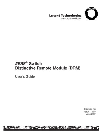
Installing the SwitchInstallation Procedures2.Check the LEDs on the switch as described below.Switch port LEDsPower LEDFigure 2-3. Checking the LEDsWhen the switch is powered on, it performs its diagnostic self test. Self testtakes approximately 3 seconds to complete.LED BehaviorDuring the self test: Initially, the Power LED and port LEDs are all off. The Power LED turns on, then all of the port LEDs turn on brieflyduring the test.When the self test completes successfully: The Power LED remains on. The port Link/Act and Speed LEDs on the front of the switch go intotheir normal operational mode:– If the ports are connected to active network devices, the Link/ActLEDs stay on or may be blinking to indicate port activity. TheSpeed LEDs turn on for 1000 Mbps links or stay off for 10/100Mbps links.– If the ports are not connected to active network devices, the Link/Act and Speed LEDs will stay off.If the LED display is different than what is described above, the self testhas not completed correctly. Refer to chapter 4, “Troubleshooting” fordiagnostic help.2-8
Installing the SwitchInstallation Procedures3. Mount the SwitchAfter the switch passes self test, it is ready to be mounted in a stable location.The switch can be mounted in these ways: on a horizontal surface on a wall under a table rack or cabinet (1410-16G Switch and 1410-24G Switch only)Rack or Cabinet MountingThe 1410-16G Switch and 1410-24G Switch can be rack mounted using theincluded brackets.Note that the mounting brackets have multiple mounting holes and can berotated allowing for a wide variety of mounting options. Secure the rack inaccordance with the manufacture’s safety guidelines.WARNINGFor safe operation, please read the mounting precautions onpage 2-3, before mounting a switch.EquipmentCabinetNoteThe 12-24 screws supplied with the switch are the correct threading forstandard EIA/TIA open 19-inch racks. If installing the switch in an equipmentcabinet such as a server cabinet, use the clips and screws that came with thecabinet in place of the 12-24 screws that are supplied with the switch.2-9
Installing the SwitchInstallation ProceduresRack Mounting the SwitchNoteRequires optional mounting bracket kit (not included).1.Use a #1 Phillips (cross-head) screwdriver and attach the mountingbrackets to the switch with the included 8-mm M4 screws.8 mmM4 screwsFigure 2-4. Attaching mounting brackets to the 1410-16G Switch8 mmM4 screwsFigure 2-5. Attaching mounting brackets to the 1410-24G Switch2-10
Installing the SwitchInstallation ProceduresNoteThe mounting brackets have multiple mounting holes and can be rotatedallowing for a wide variety of mounting options. These include mounting theswitch so that its front face is flush with the face of the rack, or mounting itin a more balanced position.WARNINGFor safe reliable installation, only use the screws provided in theaccessory kit to attach the mounting brackets to the switch.2.Hold the switch with attached brackets up to the rack and move itvertically until rack holes line up with the bracket holes, then insert andtighten the four number 12-24 screws holding the brackets to the rack.Install 12-24screwsFigure 2-6. Mounting the 1410-16G Switch in a rack2-11
Installing the SwitchInstallation ProceduresInstall 12-24screwsFigure 2-7. Mounting the 1410-24G Switch in a rack2-12
Installing the SwitchInstallation ProceduresWall or Under-Table MountingYou can mount the switch on a wall or under a table. A special kit for wall andunder-table mounting is included with the switch.WARNINGFor safe operation, do not mount any of the switches with sideventilation ducts facing up or down.For the 1410-24G Switch, the network ports must be facing up. Do notmount the switch with ports facing down.For the 1410-16G Switch and 1410-8G Switch, the network ports mayface up or down.CautionThe switch should be mounted only to a wall or wood surface that is at least1/2-inch (12.7 mm) plywood or its equivalent.1.Position the mounting template (included in the Quick Setup Guide) inthe required location, and mark the position for the mounting screws.2.Use a #1 Phillips (cross-head) screwdriver and two of the included 20-mmM4 tap screws to mount the switch on the wall or wood surface.Wall plugs are included in the accessory kit for use with plastered brickor concrete walls.RJ-45 PortsWallWall plugs20-mm M4tap screwsFigure 2-8. Wall Mounting the Switch2-13
Installing the SwitchInstallation Procedures3.For under-table mounting, a third 20-mm M4 tap screw can be placedagainst one side of the switch to secure it in place.Horizontal Surface MountingPlace the switch on a table or other horizontal surface. The switch comes withrubber feet in the accessory kit that can be used to help keep the switch fromsliding on the surface.Attach the rubber feet to the four corners on the bottom of the switch withinthe embossed angled lines. Use a sturdy surface in an uncluttered area. Youmay want to secure the networking cables and switch power cord to the tableleg or other part of the surface structure to help prevent tripping over thecords.CautionEnsure the air flow is not restricted around the sides and back of the switch.Figure 2-9. Horizontal Surface Mounting2-14
Installing the SwitchInstallation ProceduresUsing a Kensington Security CableTo prevent unauthorized removal of the switch, you can use a Kensington SlimMicroSaver security
Rack-mount accessory kit: † Read Me First † Switch Quick Setup Guide † Safety and Regulatory information † Software End User License and Hardware Warranty information 1410-8G Switch and 1410-16G Switch 1410-24G Switch Kit number 5066-0621 Contains: † three 3/4" (20-mm M4) screws for wall and under-table mounting † three wall anchors