Transcription
Model 4-710dFour-Channel Tone-BlendingMic PreamplifierUniversal Audio Part Number 65-00051Revision AUniversal Audio, Inc.Customer Service & Tech Support: 1-877-MY-UAUDIOBusiness, Sales & Marketing: 1-866-UAD-1176www.uaudio.com
NoticesThis manual provides general information, preparation for use, installation and operating instructionsfor the Universal Audio Model 4-710d.DisclaimerThe information contained in this manual is subject to change without notice. Universal Audio, Inc.makes no warranties of any kind with regard to this manual, including, but not limited to, the impliedwarranties of merchantability and fitness for a particular purpose. Universal Audio, Inc. shall not beliable for errors contained herein or direct, indirect, special, incidental, or consequential damages inconnection with the furnishing, performance, or use of this material.Copyright 2011 Universal Audio, Inc. All rights reserved.This manual and any associated software, artwork, product designs, and design concepts are subjectto copyright protection. No part of this document may be reproduced, in any form, without prior writtenpermission of Universal Audio, Inc.Trademarks4-710d, 710, Twin-Finity, 4110, 8110, SOLO/110, SOLO/610, 2-610, LA-610, LA-2A, 2-LA2, LA-3A,6176, 1176LN, 2-1176, 2192, DCS Remote Preamp, UAD and the Universal Audio, Inc. logo aretrademarks of Universal Audio, Inc. Other company and product names mentioned herein aretrademarks of their respective companiesFCC ComplianceThis device complies with Part 15 of the FCC Rules. Operation is subject to the following twoconditions: (1) this device may not cause harmful interference, and (2) the device must accept anyinterference received, including interference that may cause undesired operation.Contents of This BoxThis package should contain: (1) Universal Audio 4-710d unit (1) Set of 4 rack mounting screws with washers (1) User Manual (1) Tip In Sheet (1) IEC power cable (1) Warranty Registration Card (1) UA full line catalogii
NoticesImportant Safety InformationBefore using this unit, be sure to carefully read the applicable items of these operating instructions and thesafety suggestions. Afterwards, keep them handy for future reference. Take special care to follow the warningsindicated on the unit, as well as in the operating instructions.1. Water and Moisture - Do not use the unit near any source of water or in excessively moist environments.2. Object and Liquid Entry - Care should be taken so that objects do not fall, and liquids are not spilled, intothe enclosure through openings.3. Ventilation - When installing the unit in a rack or any other location, be sure there is adequate ventilation.Improper ventilation will cause overheating, and can damage the unit.4. Heat - The unit should be situated away from heat sources, or other equipment that produce heat.5. Power Sources - The unit should be connected to a power supply only of the type described in theoperating instructions, or as marked on the unit.6. Power Cord Protection - AC power supply cords should be routed so that they are not likely to be walkedon or pinched by items placed upon or against them. Pay particular attention to cords at plugs,convenience receptacles, and the point where they exit from the unit. Never take hold of the plug or cordif your hand is wet. Always grasp the plug body when connecting or disconnecting it.7. Grounding of the Plug - This unit is equipped with a 3-wire grounding type plug, a plug having a third(grounding) pin. This plug will only fit into a grounding-type power outlet. This is a safety feature. If youare unable to insert the plug into the outlet, contact your electrician to replace your obsolete outlet. Donot defeat the purpose of the grounding-type plug.8. Cleaning - Follow these general rules when cleaning the outside of your 4-710d:a. Turn the power Off and unplug the unitb. Gently wipe with a clean lint-free clothc.If necessary, moisten the cloth using lukewarm or distilled water, making sure not to oversaturate itas liquid could drip inside the case and cause damage to your 4-710dd. Use a dry lint-free cloth to remove any remaining moisturee.Do not use aerosol sprays, solvents, or abrasives9. Nonuse Periods - The AC power supply cord of the unit should be unplugged from the AC outlet when leftunused for a long period of time.10. Damage Requiring Service - The unit should be serviced by a qualified service personnel when:a. The AC power supply cord or the plug has been damaged; orb. Objects have fallen or liquid has been spilled into the unit; orc. The unit has been exposed to rain; ord. The unit does not operate normally or exhibits a marked change in performance; ore. The unit has been dropped, or the enclosure damaged.11. Servicing - The user should not attempt to service the unit beyond that described in the operatinginstructions. All other servicing should be referred to qualified service personnel.iii
Table Of ContentsNotices . iiIntroduction . 5A Letter from Bill Putnam Jr. .5Overview .6Features .6The Two Page, Two Minute Guide to Getting Started . 7Front Panel Descriptions. 9Analog Controls .9Digital Controls .12Rear Panel Descriptions . 14Digital Connectors .14Analog Connectors .15Interconnection Diagrams . 17Analog-Only Setup .17Basic Digital Setup .18Advanced Digital Setup .19Model 4-710d Overview . 20Digital Clocking Primer. 23Insider’s Secrets . 25History of the Model 4-710d . 27Glossary of Terms . 29Maintenance. 34Calibration .34Fuse .34Voltage Select .34Service .34AES/EBU DB-25 Connector Pinouts .34Session Recall Sheet . 35Block Diagram . 36Specifications. 37Analog Section, Channels 1–4 .37Analog-To-Digital Converter Section .39Digital Output Section .40Connector Types .40Mechanical and Power .40Index. 41Additional Resources . 43Universal Audio Website .43Product Registration .43Warranty .43Service & Support .43iv
IntroductionA Letter from Bill Putnam Jr.Thank you for purchasing the Model 4-710d Four-Channel Tone Blending Mic Preamplifer — UniversalAudio's new analog digital hybrid product. The 4-710d combines four channels of our Model 710Twin-Finity preamplifier with eight channels of pristine analog-to-digital conversion and adds acomplement of modern convenience features, all in a 2U, all-metal chassis at an amazing price.Our all-original 710 Twin-Finity preamp with Tone Blending has proved to be wildly popular amongengineers, producers, and artists seeking a broad palette of sounds from clean to warm in a single,affordable unit. The innovative preamp design of the Model 710 combines both the classic retrowarmth of UA tube design and the transient bite of solid-state. The 710 was created specifically toadd the tonal versatility and sonic inspiration missing from generic audio interface preamps. The keyto its sonic flexibility lies in its innovative circuit design, featuring a solid-state transimpedance inputamp simultaneously driving separate, phase-aligned tube and solid-state gain stages, which are thensummed to a single output. The mix between the single-ended class-A triode tube stage and solidstate transimpedance stage is controlled via a unique “Blend” knob. Blending is continually variablebetween 100% tube and 100% solid-state offering a practically infinite range of unique preamp tonesand the ability to easily dial in your own signature sound.With the 4-710d, we've added even more value to the 710 mic preamps. Each channel includes an1176-style compressor; this dynamics circuit sounds incredible and provides yet another dimension ofavailable sounds. For flexible signal routing and external processing, the 4-710d also includessend/return jacks in each preamp that can be individually switched via the front panel.The 4-710d facilitates easy integration of analog signals into your digital world with its built-in highquality 8-channel A/D converter. Selectable sample rates from 44.1 to 192 kHz, digital output via ADAToptical or AES/EBU via industry-standard DB-25 connector, and flexible low-jitter clocking optionsmake it easier than ever to get mic, line, or instrument signals directly into your DAW with a minimumof hardware and fuss. The A/D converters include LED metering, and an 8-channel soft limiter helpsprevent digital overs.Most of us at Universal Audio are musicians and/or recording engineers. We love the recording process,and we really get inspired when tracks are beautifully recorded. Our design goal for the4-710d was to build a hybrid mic preamp and A/D converter that we would be delighted to useourselves—one that would induce that “a-ha” feeling you get when hearing music recorded in itsmost natural, inspired form.Developing the Model 4-710d – as well as Universal Audio’s entire line of quality audio productsdesigned to meet the needs of the modern recording studio while retaining the character of classicvintage equipment – has been a very special experience for me and for all who have been involved.While, on the surface, the rebuilding of UA has been a business endeavor, it's really been so muchmore than that: in equal parts a sentimental and technical adventure.We thank you, and we thank my father, Bill Putnam.Sincerely,Bill Putnam Jr.5
IntroductionOverviewThe Universal Audio 4-710d is a four-channel microphone/line preamplifier with tube and solid-statetone blending, offering four additional line inputs, dynamics control, and eight channels of pristineanalog-to-digital conversion. The 4-710d combines UA’s classic design approach with several moderninnovations, creating a unique studio device suited to a wide range of applications.At the core of the 4-710d are four channels of tone-blending “Twin-Finity” mic preamps with truebypass 1176-style compression. Each of the four mic preamp channels allows for continuouslyvariable phase-aligned tone between 100% tube and 100% solid-state. Send and return jacks areavailable for external processing or signal access.The eight analog inputs are digitized via high-quality 24-bit A/D converters at selectable sample ratesup to 192 kHz. Digital output is available via dual ADAT “lightpipe” or AES/EBU DB-25 connectors,facilitating integration with most popular audio interfaces.FeaturesPreamplifiers Four TEC Award-winning 710 Twin-Finity microphone/line preamps, each featuring:Dual-path 285-volt Class-A tube and transimpedance solid-state preampsPhase-aligned tone-blending of tube and solid state circuits, creamy to crunchyNewly designed 1176-style compression circuit per preamp channelJFET Direct Input with 2.2MΩ ultra Hi-Z impedance w/auto input overrideLarge backlit VU meters for flexible metering of input drive, gain level, and gain reductionBalanced send/return inserts (half-normalled)48V phantom power75 Hz low cut filterPolarity switchMonolithic balanced output stageAnalog-to-Digital Conversion Eight channels of high quality 24-bit A/D conversion:Selectable sample rates up to 192 kHzDigital output via dual ADAT optical and AES/EBU DB-25 connectors8-channel soft limiter (switchable for all channels)Ultra-low jitter clock subsystemLED metering array with clip/hold indicators75Ω BNC work clock I/ODigital outputs anti-pop protection on power-upOther Universal voltage internal power supplyHeavy-duty metal construction, two-space rack unitOne year warranty including parts and labor6
The Two Page, Two Minute Guide to Getting StartedNo one likes to read owner’s manuals. We know that.We also know that you know what you’re doing—why else would you have bought our product?So we’re going to try to make this as easy on you as possible. Hence this two-page spread, which weestimate will take you approximately two minutes to read. It will tell you everything you need to know toget your Universal Audio 4-710d up and running, without bogging you down with details.Of course, even the most expert of us has to crack a manual every once in awhile. As the saying goes,“as a last resort, read the instructions.” You’ll find those details you’re craving—a full description ofall front and rear panel controls, interconnection diagrams, insider’s secrets, history, theory,maintenance information, block diagrams, specifications, even a glossary of terms—in the pages thatfollow.Manual conventions: Means that this is an especially useful tip Means that this is an especially important bit of informationAnd when we need to direct you to a page or section elsewhere in the manual, we’ll use the universal signsfor rewind ( ) or fast forward ( ).Getting Started With Your 4-710d:Step 1: Place the 4-710d where you intend to use it. Chassis mounting hardware is provided, allowingthe 4-710d to be used in a standard 19" rack (taking just two spaces), and so we recommend that the4-710d be securely mounted in a rack if possible.Step 2: Mute your monitors and then, using a balanced cable with XLR connectors, connect the 4710d’s rear panel line output(s) to the appropriate input(s) on your patch bay, mixer, or DAW.Step 3: Set the front panel 48V (phantom power), 15dB PAD, and LOW CUT switches to their down(OFF) position.Step 4: Set the front panel POLARITY switch to its down (IN ø) position.Step 5: Connect the desired input source to one of the 4-710d’s rear panel balanced XLR mic and/orline inputs ( page 15). Alternatively, an electric guitar or bass can be connected to a front panelunbalanced 1/4" Hi-Z input ( page 9); however, note that the 4-710d’s jack sensing circuitryautomatically disconnects the channel’s rear-panel mic and line inputs when a cable is inserted intothat channel’s Hi-Z input. ( See page 17 for interconnection diagrams)Step 6: If you are using a microphone or line-level input, set the channel’s front panel Input Selectswitch to Mic or Line.Step 7: Set the channel’s Meter switch to DRIVE (its down position).Step 8: Set the channel’s Gain control to “0” and the Level control to approximately “5”.Step 9: Set the channel’s Blend knob to its twelve o’clock position. This ensures an equal blend ofboth of the 4-710d preamplifiers (solid-state and vacuum tube).7
Getting StartedStep 10: Make sure the Power switch is off (down position) and then connect the supplied IEC powercable to the rear panel AC power connector.Step 11: Power on the 4-710d. The front-panel meters will light up. Because the Model 4-710d utilizes a tube, it needs several minutes to achieve a stableoperating temperature. During warm-up, audio quality may vary slightly.Step 12: If a microphone requiring 48 volts of phantom power is connected to the 4-710d, turn on thechannel’s 48V switch.Step 13: Unmute your monitors and slowly raise the channel’s Gain control. You should now behearing signal, with that channel’s meter becoming active.Step 14: While viewing the meter, set the channel’s Gain control until optimum input signal strengthis achieved. Change the channel’s Meter switch to OUTPUT (its up position) and set the Level controluntil optimum output signal strength is achieved.Step 15: Experiment with differing degrees of Gain to hear the various amounts of coloration the 4710d can impart to your signal. (CAUTION: Very high Gain settings will result in significant amounts ofdistortion). For the cleanest, most uncolored signal from the 4-710d, set the Gain knob to its lowestusable setting, change the Meter to OUTPUT, and then adjust the Level control as necessary. If youhear distortion when using a connected microphone even at the lowest Gain level, employ the -15 dBpad to reduce the input level. If you hear low frequency rumble, employ the Low Cut filter switch.Step 16: Finally, experiment with the Blend control to hear the different sonic signatures imparted bythe two discrete preamplifiers contained within the 4-710d. At the fully counterclockwise (TRANS)position, only signal from the solid-state preamplifier is heard. At the fully clockwise (TUBE) position,only the signal from the tube preamplifier is heard. Most uniquely, it is the in-between settings thatallow you to access the “twin-finity” of sounds offered by the 4-710d and create a custom blend thatbest complements your signal source. For more detailed information, refer to the “Front Panel” and “Rear Panel” sections onpages 9 and 14 of this manual.8
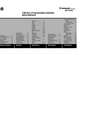
Front Panel DescriptionsAnalog Controls The controls for channels 1-4 are identical, so each control is only described once.(1) Hi-Z Inputs - Connect a high impedance signal from an instrument such as electric guitar or bassto these standard unbalanced 1/4" phone jack connectors. The 4-710d’s jack detection circuitryautomatically switches from the selected rear panel MIC or LINE input to the channel’s front panel Hi–Z input whenever a plug is inserted into this jack. The Hi-Z input impedance is 2.2MΩ for all fourinputs. These JFET direct inputs provide maximum fidelity with no high-end loss. Making a connection to the 4-710d’s front panel Hi-Z input jack automatically disconnectsany signal arriving at the rear panel mic and line input.(2) Gain - Adjusts the gain of the channel’s input stage. Turning this knob clockwise raises theamount of gain applied to the input signal. This control also determines the level sent to thecompressor if the compression circuit ( #13 on page 11) is engaged.(3) Blend (“ ”) - This unique control sets the relative contribution from the solid-state and vacuumtube preamplifier circuits. When in the fully counterclockwise (TRANS) position, only signal from thesolid-state preamplifier is heard. When in the fully clockwise (TUBE) position, only the signal from thetube preamplifier is heard. At the twelve o’clock position, signal from both the solid-state and tubepreamplifiers is heard at equal amounts.9
Front Panel(4) Level - This is the channel’s master volume control. It determines the amplitude of the signal sentto the rear panel LINE OUTPUT ( #8 on page 16) and INSERT SEND ( #11 on page 16) jacks. Thiscontrol also sets the level sent to the A/D converter inputs. The numeric values for the Gain and Level knobs are relative scale markings and do notrepresent specific dB values. You can come up with many useful tonal variations by experimenting with different Gainand Level settings.(5) 48V - Most modern condenser microphones require 48 volts of phantom power to operate. Whenin the up position, 48 volts of phantom power are available at the channel’s rear panel MIC INPUT.( See page 21 for more information about phantom power) Keep phantom power off (switch down) when it is not required. Always check the power requirements of your microphone with the manufacturer beforeapplying phantom power. To avoid loud transients, always make sure phantom power is off when connecting ordisconnecting microphones.(6) -15 dB PAD - When enabled (placed in the up position), the channel’s MIC INPUT signal will bereduced by 15 dB (this switch has no effect on LINE INPUT or Hi-Z signal). Use the PAD to reduce theincoming signal in cases where undesired distortion is present at low gain levels (for instance, whereespecially sensitive microphones are used on loud instruments or if the A/D converter is clipping).(7) Input Select - Determines whether the channel’s MIC (up position) or LINE (down position) input isactive. If the channel’s Hi-Z input is in use, this switch has no effect.( See “Analog Connectors” on page 15 for more info on the rear panel inputs)(8) Meter - This standard VU meter can display the channel’s overall output level, tube drive level, oramount of compressor gain reduction. The function that is displayed depends upon the setting of theMeter Function switch ( #9 on page 11).10
Front Panel(9) Meter Function - This three-position switch determines what the channel’s VU meter displays. Inthe up (OUTPUT) position, it shows the final output level in dB. "0" on the VU meter corresponds to 4dBu at the analog outputs and -16 dBFS at the A/D converter inputs. In the down (DRIVE) position, itshows the input level to the tube stage after the front panel Gain control, but before the Blend andLevel controls, thus giving an accurate gauge of how hard the tube and solid-state preamplifiers arebeing driven. In the center (GR) position, the meter displays the amount of gain reduction occurring inthe channel’s compressor if the COMP switch ( #13 below) is engaged for the channel. If thechannel’s compressor is off, the meter will not deflect from zero when set to GR.When the switch is in DRIVE mode, the meter is calibrated so that 0 VU is equal to 1.2% THD on a 1kHzsine wave. When OUTPUT is selected, a meter reading of 0 VU corresponds to a level of 4 dBu at therear panel LINE OUTPUT jack.( See “Drive Metering” on page 25 for additional analog metering info)(10) Low Cut - When enabled (placed in the up position), the channel’s input signal passes through a75 Hz low cut filter. This is normally used to eliminate rumble and other unwanted low frequenciesfrom an incoming signal.( See page 21 for more information about low cut filtering)(11) Polarity (“ø”) - Determines the polarity of the channel’s LINE OUTPUT ( #8 on page 16) andthe polarity of the signal at the A/D converter inputs. When off (in the down, IN ø position), pin 2 of theLINE OUTPUT is hot (positive). When the switch is enabled (in the up, OUT ø position), the output signalis placed out of phase and pin 3 of its LINE OUTPUT is hot (positive). Normally the switch should be offand only enabled when it is desirable to reverse the polarity, i.e., in cases where more than onemicrophone is utilized in recording a source signal.( See page 21 for more information about polarity inversion)(12) Insert – When enabled (placed in the up position), the input signal is routed through the channel’s insert jacks on the rear panel ( “Insert Loop” on page 16) for external processing. Whendisengaged (in the down position), the signal at the return jack is ignored. The insert switch allows youto leave external processors conveniently connected when you don’t want to currently use them on thechannel. The Send jack is active even when Insert is disengaged, so you can route the channel’ssignal to a monitor mix, tuner, etc.(13) Comp – This three-position switch controls the channel’s 1176-style analog compressor. Thecompressor has a compression ratio of 4:1 and the threshold is 10 dBu.When in the up (FAST) position, the compressor attack time is 0.3 ms and the release time is 100 ms.When in the down (SLOW) position, the attack time is 2.0 ms and the release time is 1100 ms.If the METER FUNCTION switch ( #9 above) is set to GR, the amount of compressor gain reduction isdisplayed in the METER.11
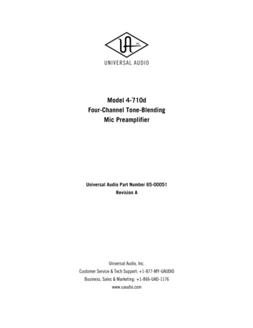
Front PanelDigital Controls(14) Power - Turns the 4-710d power on or off. When powered on, the front panel meters light up. The 4-710d should be powered off when it is not being used for extended periods of time.(15) Bit Depth – This switch determines the bit depth, or resolution, of the digital output signal for alleight A/D channels. In the up position, the digital output word length is 24 bits; in the down position,the digital output word length is 16 bits.The actual A/D conversion of the 4-710d is always performed at a 24-bit word length. When the switchis set to 16-bit mode, the 24-bit signal is triangular dithered to 16 bits.(16) Limit 1-8 – This switch activates the built-in analog limiter for all eight inputs prior to A/Dconversion. The limiter is global for all eight inputs; it cannot be individually enabled per channel(unlike the mic pre compressors on channels 1-4).The limiter threshold is 17dBu ( -3dBFS) and the ratio is effectively infinite. The attack time is 0.075ms and the release time is 100 ms. Although the limiter will help prevent “digital overs” (A/D clipping)during conversion, it is not a “brick wall” limiter. It is still possible to clip the A/D input, especiallywith very hot signal levels and/or signals with fast transient peaks.(17) Sample Rate - This knob defines the internal sample rate of the A/D converter or selects externalclocking. The following sample rates are supported (kHz): 44.1, 48, 88.2, 96, 176.4, and 192.When Sample Rate is set to W/C (external word clock) the 4-710d is a word clock slave and theincoming clock rate at the rear panel’s BNC Word Clock In connector ( #2 on page 14) is used todetermine the sample rate for A/D conversion.( For more details, please see the “Digital Clocking Primer” section on page 23)12
Front Panel(18) Digital Out Level - These LEDs indicate the signal level of the A/D converters. Each of the eightA/D channels has its own two-segment level indicato
The 4-710d facilitates easy integration of analog signals into your digital world with its built-in high quality 8-channel A/D converter. Selectable sample rates from 44.1 to 192 kHz, digital output via ADAT optical or AES/EBU via industry-standard DB-25 connector, and flexible low-jitter clocking options