Transcription
!IC-M505.qxd06.3.28 2:57 PMPage A (1,1)New2001INSTRUCTION MANUALVHF MARINE TRANSCEIVERiM505
!IC-M505.qxd06.3.28 2:57 PMPage i (1,1)New2001FOREWORDIMPORTANTThank you for purchasing this Icom product. The IC-M505VHF MARINE TRANSCEIVER is designed and built with Icom’sstate of the art technology and craftsmanship. With propercare, this product should provide you with years of troublefree operation.READ ALL INSTRUCTIONS carefully and completelyWe want to take a couple of moments of your time to thankyou for making the IC-M505 your radio of choice, and hopeyou agree with Icom’s philosophy of “technology first.” Manyhours of research and development went into the design ofyour IC-M505.D FEATURES Simple operation with large keys Easy to hear speaker Built-in DSC meets ITU Class D requirementbefore using the transceiver.SAVE THIS INSTRUCTION MANUAL — This instruction manual contains important operating instructions forthe IC-M505.EXPLICIT DEFINITIONSWORDDEFINITIONPersonal injury, fire hazard or electric shockR WARNING!may occur.CAUTIONNOTEEquipment damage may occur.Recommended for optimum use. No risk ofpersonal injury, fire or electric shock. Rugged waterproof construction Optional COMMANDMIC III (HM-162E) isavailableIcom, Icom Inc. and thelogo are registered trademarks of Icom Incorporated (Japan) in the United States, the United Kingdom, Germany, France,Spain, Russia and/or other countries.COMMANDMIC III is a trademark of Icom Incorporated (Japan) in the UnitedStates.iCLEAN THE TRANSCEIVER AND MICROPHONE THOROUGHLY WITH FRESH WATER after exposure to waterincluding salt, otherwise, the keys and switch may becomeinoperable due to salt crystallization.
!IC-M505.qxd06.3.28 2:57 PMPage ii (1,1)New2001IN CASE OF EMERGENCYINSTALLATION NOTEIf your vessel requires assistance, contact other vessels andthe Coast Guard by sending a Distress call on Channel 16.The installation of this equipment should be made in such amanner as to respect the EC recommended electromagneticfield exposure limits (1999/519/EC).USING CHANNEL 16DISTRESS CALL PROCEDURE1. “MAYDAY MAYDAY MAYDAY.”2. “THIS IS .” (name of vessel).3. Say your call sign or other indication of the vessel (AND9-digit DSC ID if you have one).4. “LOCATED AT .” (your position).5. State the nature of the distress and assistance required.6. Give any other information which might facilitate therescue.Or, transmit your Distress call using digital selective callingon Channel 70.USING DIGITAL SELECTIVE CALLING (Ch 70)DISTRESS CALL PROCEDURE1. While lifting up the key cover, push and hold[DISTRESS] for 5 sec. until you hear 5 short beepschange to one long beep.2. Wait for an acknowledgment on Channel 70 from a coaststation. After the acknowledgement is received, Channel 16 is automatically selected.The maximum RF power available from this device is 25watts. The antenna should be installed as high as possiblefor maximum efficiency and that this installation height shouldbe at least 5 meters above ground (or accessible) level. In thecase where an antenna cannot be installed at a reasonableheight, then the transmitter should neither be continuouslyoperated for long periods if any person is within 5 meters ofthe antenna, nor operated at all if any person is touching theantenna.In all cases any possible risk depends on the transmitterbeing activated for long periods. (actual recommendation limits are specified as an average of 6 minutes) Normally thetransmitter is not active for long periods of time. Some radio licenses will require that a timer circuit automatically cuts thetransmitter after 1–2 minutes etc.Similarly some types of transmitter, SSB, CW, AM, etc. have alower ‘average’ output power and the perceived risk is evenlower.3. Push and hold [PTT], then transmit the appropriateinformation as listed above.ii
!IC-M505.qxd06.3.28 2:57 PMPage iii (1,1)New2001DOCThis warning symbol indicates that this equipment operates in non-harmonised frequencybands and/or may be subject to licensing conditions in the country of use. Be sure to check thatyou have the correct version of this radio or thecorrect programming of this radio, to comply withnational licensing requirement.CE versions of the IC-M505 which display the“CE” symbol on the serial number seal, complywith the essential requirements of the European Radio and Telecommunication TerminalDirective 1999/5/EC.DECLARATIONOF CONFORMITYWe Icom Inc. Japan1-1-32, Kamiminami, Hirano-kuOsaka 547-0003, JapanDeclare on our sole responsibility that this equipment complies with theessential requirements of the Radio and Telecommunications TerminalEquipment Directive, 1999/5/EC, and that any applicable Essential TestSuite measurements have been performed.Kind of equipment:VHF MARINE TRANSCEIVERType-designation:iM505Version (where applicable):056028th Feb. 2006Place and date of issueAuthorized representative nameThis compliances is based on conformity with the following harmonisedstandards, specifications or documents:i)EN 301 025-2V1.2.1 (2004-09)ii) EN 301 025-3V1.2.1 (2004-09)iii) EN 609452002iv) EN 60950-12001v) EN 300 698-2V1.1.1 ( 2000-08)vi) EN 300 698-3V1.1.1 ( 2001-05)Signatureiii
!IC-M505.qxd06.3.28 2:57 PMPage iv (1,1)New2001TABLE OF CONTENTSFOREWORD iIMPORTANT iEXPLICIT DEFINITIONS iIN CASE OF EMERGENCY iiINSTALLATION NOTE iiDOC iiiTABLE OF CONTENTS ivPRECAUTIONS v1 OPERATING RULES 12 PANEL DESCRIPTION 2–5 Front panel 2 Function display 4 Microphone 53 BASIC OPERATION 6–11 Channel selection 6 Receiving and transmitting 8 Call channel programming 9 Channel comments 10 Microphone Lock function 10 Display backlight 10 Optional voice scrambler operation 114 SCAN OPERATION 12–13 Scan types 12 Setting TAG channels 13 Starting a scan 135 DUALWATCH/TRI-WATCH 14 Description 14 Operation 146 DSC OPERATION 15–49 MMSI code programming 15 MMSI code check 16 DSC address ID 17 Position and time programming 21 Position and time indication 22 GPS information indication 22 Distress call 23 Transmitting DSC calls 26 Receiving DSC calls 41 Received messages 45 DSC Set mode 477 OTHER FUNCTIONS 50–54 Intercom operation 50 RX Speaker function 51 Hailer operation 52 Automatic foghorn function 538 SET MODE 55–57 Set mode programming 55 Set mode items 559 CONNECTIONS AND MAINTENANCE 58–64 Connections 58 Antenna 59 Fuse replacement 59 Supplied accessories 59 Microphone hanger 59 Mounting the transceiver 60 MB-75 installation 61 UT-112/UT-98 installation 62 HM-162E installation 6310 TROUBLESHOOTING 6611 SPECIFICATIONS AND OPTIONS 67–68 Specifications 67 Options 6812 CHANNEL LIST 69–70TEMPLATE123456789101112iv
PRECAUTIONSRWARNING! NEVER connect the transceiver to an ACBE CAREFUL! The transceiver rear panel will becomeoutlet. This may pose a fire hazard or result in an electricshock.hot when operating continuously for long periods.Place the transceiver in a secure place to avoid inadvertentuse by children.NEVER connect the transceiver to a power source of morethan 16 V DC or use reverse polarity. This will ruin the transceiver.NEVER cut the DC power cable between the DC plug at theback of the transceiver and fuse holder. If an incorrect connection is made after cutting, the transceiver may be damaged.NEVER place the transceiver where normal operation of thevessel may be hindered or where it could cause bodily injury.KEEP the transceiver at least 1 m away from the ship’s navigation compass.DO NOT use or place the transceiver in areas with temperatures below –20 C or above 60 C or, in areas subject to direct sunlight, such as the dashboard.AVOID the use of chemical agents such as benzine or alcohol when cleaning, as they may damage the transceiversurfaces. If the transceiver becomes dusty or dirty, wipe itclean with a soft, dry cloth.vBE CAREFUL! The transceiver and the optional HM162E COMMANDMIC III employ waterproof construction,which corresponds to IPX8 of the international standard IEC60529 (2001). However, once the transceiver or microphonehas been dropped, waterproofing cannot be guaranteed dueto the fact that the case may be cracked, or the waterproofseal damaged, etc.
!IC-M505.qxd06.3.28 2:57 PMPage 1 (1,1)OPERATING RULESD PRIORITIES Read all rules and regulations pertaining to priorities andkeep an up-to-date copy handy. Safety and Distress callstake priority over all others. You must monitor Channel 16 when you are not operatingon another channel. False or fraudulent distress signals are prohibited and punishable by law.D PRIVACY Information overheard but not intended for you cannot lawfully be used in any way.1(2) OPERATOR’S LICENSEA Restricted Radiotelephone Operator Permit is the licensemost often held by small vessel radio operators when a radiois not required for safety purposes.1The Restricted Radiotelephone Operator Permit must beposted or kept with the operator. Only a licensed radio operator may operate a transceiver.However, non-licensed individuals may talk over a transceiverif a licensed operator starts, supervises, ends the call andmakes the necessary log entries.Keep a copy of the current government rules and regulationshandy. Indecent or profane language is prohibited.D RADIO LICENSES(1) SHIP STATION LICENSEYou must have a current radio station license before using thetransceiver. It is unlawful to operate a ship station which is notlicensed.Inquire through your dealer or the appropriate governmentagency for a Ship-Radiotelephone license application. Thisgovernment-issued license states the call sign which is yourcraft’s identification for radio purposes.1
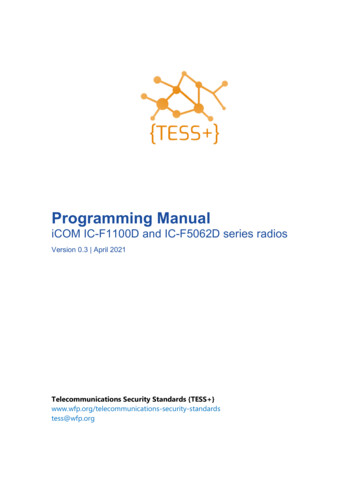
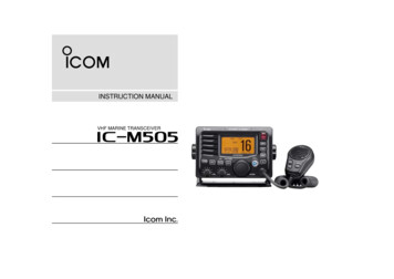
!IC-M505.qxd06.3.28 2:57 PMPage 2 (1,1)New20012PANEL DESCRIPTION Front panelSpeakerFunction display (p. 4)qwert!3!2y!1!0 oiuq DISTRESS KEY [DISTRESS]Push for 5 sec. to transmit a Distress call. (p. 23)w DSC MENU KEY [MENU]Push to toggle the DSC menu appear or disappear. (p. 15)e CLEAR KEY [CLR]Push to cancel the entered function, exit Set mode.(pgs. 9, 10, 55)2r HAIL/RX SPEAKER KEY [HAIL RX ] Push to turn the hailer mode ON or OFF. (p. 52) Push and hold for 1 sec. to turn the RX Speaker modeON or OFF. (p. 51) While pushing and holding [H/L], push to turn the autofoghorn function ON. (p. 54)t INTERCOM KEY [IC] Push to activate an optional Intercom function. (p. 50) Push and hold to call the optional command microphone while in Intercom mode. (p. 50)y CHANNEL 16/CALL CHANNEL KEY [16 C] Push to select Channel 16. (p. 6) Push and hold for 1 sec. to select Call channel. (p. 6)CALL” appears when Call channel is selected. “C Push and hold for 3 sec. to enter Call channel programming condition when Call channel is selected. (p. 9) While pushing and holding [H/L], push to enter thechannel comment programming condition. (p. 10) Advance the cursor while in the channel comment programming condition. (p. 10) While turning power ON, push to enter Set mode.(p. 55)
!IC-M505.qxd06.3.28 2:57 PMPage 3 (1,1)New2001PANEL DESCRIPTIONu CHANNEL SELECTOR [CHANNEL ENTER] Rotate to select the operating channels, Set mode settings, etc. (pgs. 6–8, 55) While pushing and holding [H/L], rotate to adjust thebrightness of the LCD and key backlight. (p. 10) Push to enter the input channel comment, selecteditem, etc. (pgs. 10, 55) Rotate to check TAG channels, changes scanning direction or resumes the scan manually during scan.(p. 13) While pushing and holding [HAIL RX ], rotate to adjust the audio level in RX Speaker mode. (p. 51) Push and hold for 1 sec. to display the GPS informationwhen a GPS receiver is connected. (p. 22)i DIAL/DUAL/GROUP KEY [DIAL DUAL/GRP] Push to select the regular channel. (p. 7) Push and hold for 1 sec. to start Dualwatch or Tri-watch.(p. 14) Push to stop Dualwatch or Tri-watch when either is activated. (p. 14) Move the cursor backward while in the channel comment programming condition. (p. 10) While pushing and holding [H/L], push to select the desired channel group in sequence. (p. 7)2o SQUELCH CONTROL [SQL]Rotate to set the squelch threshold level. (p. 8)2!0 SCAN/TAG KEY [SCAN TAG] (p. 13) Push to start and stop Normal or Priority scan. Push and hold for 1 sec. to set or clear the displayedchannel as a TAG (scanned) channel. While pushing and holding [H/L], push for 3 sec. toclear or set all TAG channels in the selected channelgroup.!1 VOLUME CONTROL [VOL] (p. 8)Rotate to adjust the audio level.!2 TRANSMIT POWER KEY [H/L] Push to toggle the power high or low. (p. 8) Some channels are set to low power only. While pushing this key, some keys perform secondaryfunctions.!3 POWER KEY [POWER] (p. 8) Push to turn power ON. Push and hold for 1 sec. to turn power OFF. EUR version has International channels only and this function is not available.3
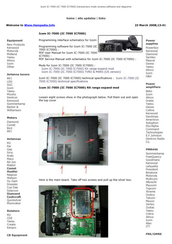
!IC-M505.qxd06.3.28 2:57 PMPage 4 (1,1)New20012PANEL DESCRIPTION Function displayq w e r t!4!3!2!1!0BUSY 25WINTRXDUPSCRAM TAGNORMAL SCAN-34 34.506N123 23.236WLocal 1:10y CALL CHANNEL INDICATOR (pgs. 6, 9)Appears when the call channel is selected.yCALLuii CHANNEL NUMBER READOUTIndicates the selected operating channel number.o CHANNEL COMMENT INDICATORChannel comment appears if programmed. (p. 10)CALLINGoq RX SPEAKER INDICATOR (p. 51)Appears during the RX Speaker mode.w POWER INDICATOR (p. 8)25W” appears when high power is selected. “21W” appears when low power is selected. “1e TAG CHANNEL INDICATOR (p. 13)Appears when a TAG channel is selected.r DUPLEX INDICATOR (p. 7)Appears when a duplex channel is selected.t CHANNEL GROUP INDICATOR (p. 7)INT,” U.S.A. “UUSA,”Indicates whether an International “IDSC” or ATIS “AATIS” channel is in use. (DependsDSC “Don version)4u LOW BATTERY INDICATORBlinks when the battery voltage drops to approx. 10 V DCor below.!0 TIME ZONE INDICATOR Shows the current time data when a GPS receiver isconnected.?” may blink every 2 sec. instead of current time data when “?the GPS current time data is invalid.?” may blink every 2 sec. instead of current time data 4 “?hours after the time data is input manually, up until 23.5 hourshave past.Local” appears when the offset time data is set. “L(p. 47)No Time ” appears when no GPS receiver is con “Nnected and no time data is input manually.
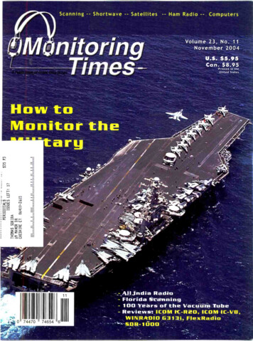
!IC-M505.qxd06.3.28 2:57 PMPage 5 (1,1)New2001PANEL DESCRIPTION2 Microphone!1 POSITION INDICATOR Shows the GPS position data.?” may blink every 2 sec. instead of position data when the “?GPS position data is invalid. In such a case, the last positiondata is held for up to 23.5 hours.?” may blink every 2 sec. instead of position data 4 hours “?after the position data is input manually, up until 23.5 hourshave past.No Position” appears when no GPS receiver is “Nconnected and no position data is input manually.!2 SCAN INDICATORPRI-SCAN 16 ” appears during Priority scan; “PNORMAL SCAN” appears during Normal scan. (p. 13)“NDUAL 16” appears during Dualwatch; “TTRI 16” ap “Dpears during Tri-watch. (p. 14)!3 SCRAMBLER INDICATOR (p. 11)Appears when the voice scrambler function is activated.(only when the optional scrambler unit is installed.)!4 BUSY/TRANSMIT INDICATOR (p. 8)BUSY” appears when receiving a signal or when the “Bsquelch opens.TX” appears while transmitting. “T2qMicrophoneweq PTT SWITCH [PTT]Push and hold to transmit; release to receive. (p. 8)Y]/[ZZ]w CHANNEL UP/DOWN KEYS [Y Push either key to change the operating memory channel, Set mode settings, etc. (pgs. 6, 7, 55) Checks TAG channels, changes scanning direction orresumes the scan manually during scan. (p. 13)e TRANSMIT POWER KEY [HI/LO] Toggles power high and low when pushed. (p. 8) Some channels are set to low power only. While pushing and holding [HI/LO], turn power ON totoggle the Microphone Lock function ON and OFF.(p. 10)5
!IC-M505.qxd06.3.28 2:57 PMPage 6 (1,1)New20013BASIC OPERATION Channel selectionï Channel 16ï Call channelChannel 16 is the distress and safety channel. It is used forestablishing initial contact with a station and for emergencycommunications. Channel 16 is monitored during both Dualwatch and Tri-watch. While standing by, you must monitorChannel 16.Each regular channel group has a separate leisure-use callchannel. The call channel is monitored during Tri-watch. Thecall channels can be programmed (p. 9) and are used to storeyour most often used channel in each channel group for quickrecall. Push [16 C] momentarily to select Channel 16. Push [DIAL DUAL/GRP] to return to the condition before selecting Channel 16, or rotate [CHANNEL] to select an operating channel. Push [16 C] for 1 sec. to select the call channel of the selected channel group.25W Push [DIAL DUAL/GRP] to return to the condition beforeselecting call channel, or rotate [CHANNEL] to select anoperating channel.INTTAGPush34 34.506N123 23.236WUTC 12:00CALL” and call channel number appear. “C Each channel group may have an independent call channel afterprogramming a call channel. (p. 9)25WPushfor 1 sec.6INTCALLCALLINGTAG34 34.506N3434.506N123 23.236W123 23.236WUTC 1212:00:00CALLING
!IC-M505.qxd06.3.28 2:57 PMPage 7 (1,1)New2001BASIC OPERATIONï International channels25WThere are pre-programmed 57 international channels for theIC-M505.USADUPTAGPush 34 34.506N3434.506N123 23.236W123 23.236WUTC 1212:00:00 PORT OPRq Push [DIAL DUAL/GRP] to select a regular channel.w While pushing and holding [H/L], push [DIAL DUAL/GRP]to change the channel group, if necessary.INT” appears when International channel is selected. “Ie Rotate [CHANNEL] to select a channel.DUP” appears for duplex channels. “D25WINTDUPTAGPush3 3ï ATIS and DSC channels(Holland and FRG versions only)For Holland and FRG version, there are pre-programmed 57ATIS and 57 DSC* channels in addition to 57 Internationalchannels.*FRG version only34 34.506N34 34.506N123 23.236W12323.236WUTC 1212:00:00 PORT OPRï U.S.A. channels (U.K. version only)For U.K. version, there are pre-programmed 58 U.S.A. channels in addition to 57 International channels.q Push [DIAL DUAL/GRP] to select a regular channel.w While pushing and holding [H/L], push [DIAL DUAL/GRP]to change the channel group, if necessary.q Push [DIAL DUAL/GRP] to select a regular channel.w While pushing and holding [H/L], push [DIAL DUAL/GRP]to change the channel group, if necessary. International, ATIS and DSC channels can be selected in sequence.e Rotate [CHANNEL] to select a channel.DUP” appears for duplex channels. “DPush1WATISTAG 25WDSCTAG International and U.S.A. channels can be selected in sequence.e Rotate [CHANNEL] to select a channel.DUP” appears for duplex channels. “DCOMMERCIALATIS channel34 34.506N3434.506N123 23.236W123 23.236WUTC 1212:00:00CALLINGDSC channel7
!IC-M505.qxd06.3.28 2:57 PMPage 8 (1,1)New20013BASIC OPERATION Receiving and transmittingCAUTION: Transmitting without an antenna may damage the transceiver.q Push [POWER] to turn power ON.w Set the audio and squelch levels. Rotate [SQL] fully counterclockwise in advance. Rotate [VOL] to adjust the audio output level. Rotate [SQL] clockwise until the noise disappears.e While pushing and holding [H/L], push [DIAL DUAL/GRP]to change the channel group. (p. 7)r Rotate [CHANNEL] to select the desired channel.(pgs. 6, 7)IMPORTANT: To maximize the readability of your transmitted signal, pause a few sec. after pushing [PTT], holdthe microphone 5 to 10 cm from your mouth and speakinto the microphone at a normal voice level.yquiMicrophoneBUSY” appears and audio is emitted When receiving a signal, “Bfrom the speaker. Further adjustment of [VOL] may be necessary.t Push [H/L] to select the output power if necessary.25W” or “11W” appears when high or low power is selected, re “2spectively. Choose low power for short range communications, choose highpower for longer distance communications. Some channels are for low power only.y Push and hold [PTT] to transmit, then speak into the microphone.TX” appears. “T Channel 70 cannot be used for transmission other than DSC.u Release [PTT] to receive.8wwertrey
!IC-M505.qxd06.3.28 2:57 PMPage 9 (1,1)New2001BASIC OPERATION3 Call channel programmingYou can program the call channel with your most often-usedchannels in each channel group for quick recall.q While pushing and holding[H/L], push [DIAL DUAL GRP] one or more times toselect the desired channelgroup (INT, USA, ATIS orDSC) to be programmed.w Push [16 C] for 1 sec. toselect the call channel ofthe selected channel group.CALL ” and call channel “Cnumber appear.e Push [16 C] again for 3 sec.(until a long beep changesto 2 short beeps) to entercall channel programming. Channel number starts blinking.r Rotate [CHANNEL] to select the desired channel.25WINTDUPTAG34 34.506N3434.506N123 23.236W123 23.236WUTC 1212:00:0025W25WINTDUPTAG34 34.506N3434.506N123 23.236W123 23.236WUTC 1212:00:00INTLINTCALLt Push [16 C] to program thedisplayed channel as thecall channel. Push [CLR] to cancel. The channel number stopsblinking.25WINTDUPTAG34 34.506N3434.506N123 23.236W123 23.236WUTC 1212:00:00CALL3INTLCALLINTLTAG34 34.506N3434.506N123 23.236W123 23.236WUTC 1212:00:0025WCALLINGINTCALLTAG34 34.506N3434.506N123 23.236W123 23.236WUTC 1212:00:00CALLING9
!IC-M505.qxd06.3.28 2:57 PMPage 10 (1,1)New20013BASIC OPERATION Channel comments Microphone Lock functionMemory channels can be labelled with a unique alphanumericID of up to 10 characters.The Microphone Lock function electrically locks [Y]/[Z] and[HI/LO] keys on the supplied microphone. This prevents accidental channel changes and function access.Capital letters, small letters, 0 to 9, some symbols (/ . –) andspace can be used. While pushing and holding [HI/LO] on the microphone, turnpower ON to toggle the Lock function ON and OFF.q Select the desired channel. Cancel Dualwatch, Tri-watch or Scan in advance.w While pushing and holding [H/L], push [16 C] to edit thechannel comment.25WINT A cursor and the first character start blinking alternately.e Select the desired character by rotating [CHANNEL].TAG[Y]/[Z][HI/LO]34 34.506N34 34.506N123 23.236W12323.236WUTC 1212:00:00PLEASUREPLEASURE Push [16 C] or [DIAL DUAL/GRP] to move the cursor forwardor backward, respectively.r Repeat step e to input all characters.t Push [CHANNEL ENTER] to input and set the comment. Push [CLR] to cancel. The cursor and the character stop blinking.y Repeat steps q to t to program other channel comments, if desired. Display backlightThe function display and keys can be backlit for better visibility under low light conditions. While pushing and holding [H/L], rotate [CHANNEL] to adjust the brightness of the LCD and key backlight. The backlight is adjustable in 7 levels and OFF.10
!IC-M505.qxd06.3.28 2:57 PMPage 11 (1,1)New2001BASIC OPERATION3 Optional voice scrambler operationD Activating the scramblerD Programming scrambler codesThe optional voice scrambler provides private communications. In order to receive or send scrambled transmissionsyou must first activate the scrambler function. To activate thefunction, an optional scrambler unit is necessary. See pgs.57, 62 for setting the scrambler unit. Ask your dealer for details.There are 32 codes (1 to 32) or 128 codes (0 to 127)* available for programming when an optional scrambler unit is installed. In order to understand one another, all transceiversin your group must have the same scramble code. This function may not be available depending on dealer setting.The scrambler function automatically turns OFF whenChannel 16 or 70 is selected.q Turn power OFF.w While pushing [16 C], turn power ON to enter set mode.e After the display appears, release [16 C].Scrambler Code,”r Rotate [CHANNEL] to select the “Spush [CHANNEL ENTER].t Rotate [CHANNEL] to select the desired scrambler code.y Push [CHANNEL ENTER] to set and exit the scramblercode item.Exit,” pushu Push [CLR], or rotate [CHANNEL] to select “E[CHANNEL ENTER] to exit set mode.q Rotate [CHANNEL] to select an operating channel otherthan Channel 16 and 70.w While pushing and holding [H/L], push [IC] to turn the optional scrambler function ON.SCRAM” appears. “Se To turn the scrambler function OFF, repeat step w.SCRAM” disappears. “S3*Depends on the installed scrambler unit.[Example]: Programming scrambler code 5.Push to enter set mode.--Set Mode- ScanScan TypeScan TimerDual/TriBeepContrastFoghorn FrequencyRadio PowerRotateto select item,then push.--Set Mode-Dual/TriBeepContrastFoghorn FrequencyRadio PowerScrambler Type Scrambler CodeSelectRotateto select code,then push.--Set Mode-Scrambler Code 5 Select4321 ENT OK 11
!IC-M505.qxd06.3.28 2:57 PMPage 12 (1,1)New20014SCAN OPERATION Scan typesScanning is an efficient way to locate signals quickly over awide frequency range. The transceiver has Priority scan andNormal scan.Set the TAG channels (scanned channel) before scanning.Clear the TAG channels which inconveniently stop scanning,such as those for digital communication use. (Refer to rightpage for details.)Choose Priority or Normal scan in Set mode. (p. 55)PRIORITY SCANNORMAL SCANCH 01CH 06CH 16CH 05CH 01CH 02CH 03CH 04Priority scan searches through all TAG channels in sequence while monitoring Channel 16. When a signal is detected on Channel 16, scan pauses until the signal disappears; when a signal is detected on a channel other thanChannel 16, scan becomes Dualwatch until the signal disappears.12CH 02CH 06CH 03CH 05CH 04Normal scan, like Priority scan, searches through all TAGchannels in sequence. However, unlike Priority scan,Channel 16 is not checked unless Channel 16 is set as aTAG channel.
!IC-M505.qxd06.3.28 2:57 PMPage 13 (1,1)New2001SCAN OPERATION4 Setting TAG channels Starting a scanFor more efficient scanning, add the desired channels as TAGchannels or clear the TAG for unwanted channels.Channels that are not tagged will be skipped during scanning.TAG channels can be assigned to each channel group (INT,USA, ATIS or DSC) independently.Set scan type (Priority or Normal scan) and scan resumetimer in advance, using Set mode. (p. 55)q While pushing and holding [H/L], push [DIAL DUAL/GRP]to select the desired channel group (INT, USA, ATIS orDSC.)w Select the desired channel to be set as a TAG channel.e Push [SCAN TAG] for 1 sec. to set the displayed channelas a TAG channel.q While pushing and holding [H/L], push [DIAL DUAL/GRP]to select the desired channel group (INT, USA, ATIS orDSC) if desired.w Set TAG channels as described at left.e Make sure the squelch is closed to start a scan.r Push [SCAN TAG] to start Priority or Normal scan.PRI-SCAN 16” appears at the channel comment indicator “Pduring Priority scan.NORMAL SCAN” appears at the channel comment indicator “Nduring Normal scan. When a signal is detected, scan pauses until the signal disappears or resumes after pausing 5 sec. according to Set modesetting. (Channel 16 is still monitored during Priority scan.) Rotate [CHANNEL] to check the scanning TAG channels, tochange the scanning direction or resume the scan manually.16” blinks at the channel comment in A beep tone sounds and “1dicator when a signal is received on Channel 16 during Priorityscan.TAG” appears in the display. “Tr To cancel the TAG channel setting, repeat step e.TAG” disappears. “T Clearing (or setting) all tagged channelsWhile pushing and holding [H/L], push [SCAN TAG] for 3sec. (until a long beep changes to 2 short beeps) to clear allTAG channels setting in the channel group. Repeat above procedure to set all TAG channels.[Example]: Starting a normal scan.Scan starts.25WINTDUPTAG34 34.506N3434.506N123 23.236W123 23.236WUTC 1212:00:00PushINTL425WWhen a signal is receivedINTDUPTAGNORMAL SCANBUSY 25WINT34 34.506N3434.506N123 23.236W123 23.236WUTC 1212:00:0034 34.506N3434.506N123 23.236W123 23.236WUTC 1212:00:00TAGNORMAL SCANSAFETY13
!IC-M505.qxd06.3.28 2:57 PMPage 14 (1,1)New20015DUALWATCH/TRI-WATCH Description OperationDualwatch monitors Channel 16 while you are receivingon another channel; Tri-watch monitors Channel 16 and thecall channel while receiving another channel. Dualwatch/Triwatch is convenient for monitoring Channel 16 when you areoperating on another channel.q Select Dualwatch or Tri-watch in Set mode. (p. 56)w Rotate [CHANNEL] to select the desired operating channel.e Push [DIAL DUAL/GRP] for 1 sec. to start Dualwatch orTri-watch.DUALWATCH/TRI-WATCH SIMULATIONCall channelDUAL 16” appears during Dualwatch; “TTRI 16” appears dur “Ding Tri-watch. A beep tone sounds when a signal is received on Channel 16.r To cancel Dualwatch/Tri-watch, push [DIAL DUAL/GRP]again.[Example]: Operating Tri-watch on INT Channel 25Tri-watch starts.25WINTDUPTAGTRI 16DualwatchTri-watch If a signal is received on Channel 16, Dualwatch/Tri-watchpauses on Channel 16 until the signal disappears. If a signal is received on the call channel during Tri-watch,Tri-watch becomes Dualwatch until the signal disappears. To transmit on the selected channel during Dualwatc
CHANNEL 16/CALL CHANNEL KEY [16 C] Push to select Channel 16. (p. 6) Push and hold for 1 sec. to select Call channel. (p. 6) " C A L L " appears when Call channel is selected. Push and hold for 3 sec. to enter Call channel program-ming condition when Call channel is selected. (p. 9) While pushing and holding [H/L], push to enter the