Transcription
User ManualPowerFlex 700 AC Drives – Frames 0 10Vector Control Firmware 4.001 and Up
Important User InformationRead this document and the documents listed in the additional resources section about installation, configuration, andoperation of this equipment before you install, configure, operate, or maintain this product. Users are required tofamiliarize themselves with installation and wiring instructions in addition to requirements of all applicable codes, laws,and standards.Activities including installation, adjustments, putting into service, use, assembly, disassembly, and maintenance are requiredto be carried out by suitably trained personnel in accordance with applicable code of practice.If this equipment is used in a manner not specified by the manufacturer, the protection provided by the equipment can beimpaired.In no event will Rockwell Automation, Inc. be responsible or liable for indirect or consequential damages resulting from theuse or application of this equipment.The examples and diagrams in this manual are included solely for illustrative purposes. Because of the many variables andrequirements associated with any particular installation, Rockwell Automation, Inc. cannot assume responsibility orliability for actual use based on the examples and diagrams.No patent liability is assumed by Rockwell Automation, Inc. with respect to use of information, circuits, equipment, orsoftware described in this manual.Reproduction of the contents of this manual, in whole or in part, without written permission of Rockwell Automation,Inc., is prohibited.Throughout this manual, when necessary, we use notes to make you aware of safety considerations.WARNING: Identifies information about practices or circumstances that can cause an explosion in a hazardous environment,which can lead to personal injury or death, property damage, or economic loss.ATTENTION: Identifies information about practices or circumstances that can lead to personal injury or death, propertydamage, or economic loss. Attentions help you identify a hazard, avoid a hazard, and recognize the consequence.IMPORTANTIdentifies information that is critical for successful application and understanding of the product.Labels can also be on or inside the equipment to provide specific precautions.SHOCK HAZARD: Labels can be on or inside the equipment, for example, a drive or motor, to alert people that dangerousvoltage can be present.BURN HAZARD: Labels can be on or inside the equipment, for example, a drive or motor, to alert people that surfaces canreach dangerous temperatures.ARC FLASH HAZARD: Labels can be on or inside the equipment, for example, a motor control center, to alert people topotential Arc Flash. Arc Flash will cause severe injury or death. Wear proper Personal Protective Equipment (PPE). Follow ALLRegulatory requirements for safe work practices and for Personal Protective Equipment (PPE).Allen-Bradley, DPI, DriveExplorer, DriveExecutive, Force Technology, PLC, PowerFlex, SCANport, Rockwell Software, Rockwell Automation, and TechConnect are trademarks of Rockwell Automation, Inc.Trademarks not belonging to Rockwell Automation are property of their respective companies.
Summary of ChangesThe information below summarizes the changes to the PowerFlex 700 UserManual, publication 20B-UM002 since the last release.New and UpdatedInformationManual UpdatesDescription of New or Updated InformationPageRemoved the product certifications and specifications from Appendix A. All certification and specificationinformation is located in the PowerFlex 700 Adjustable Frequency AC Drive Technical Data, publication 20BTD001.N/ARockwell Automation Publication 20B-UM002G-EN-P - July 20143
Summary of ChangesNotes:4Rockwell Automation Publication 20B-UM002G-EN-P - July 2014
Table of ContentsPrefaceWho Should Use this Manual? . . . . . . . . . . . . . . . . . . . . . . . . . . . . . . . . . . . . . . 9What Is Not in this Manual. . . . . . . . . . . . . . . . . . . . . . . . . . . . . . . . . . . . . . . . . 9Manual Conventions . . . . . . . . . . . . . . . . . . . . . . . . . . . . . . . . . . . . . . . . . . . . . . . 9Additional Resources . . . . . . . . . . . . . . . . . . . . . . . . . . . . . . . . . . . . . . . . . . . . . 10ATEX Approved Drives & Motors . . . . . . . . . . . . . . . . . . . . . . . . . . . . . . . . 10Drive Frame Sizes . . . . . . . . . . . . . . . . . . . . . . . . . . . . . . . . . . . . . . . . . . . . . . . . 10General Precautions . . . . . . . . . . . . . . . . . . . . . . . . . . . . . . . . . . . . . . . . . . . . . . 11Catalog Number Explanation . . . . . . . . . . . . . . . . . . . . . . . . . . . . . . . . . . . . . 13Chapter 1Programming and ParametersAbout Parameters . . . . . . . . . . . . . . . . . . . . . . . . . . . . . . . . . . . . . . . . . . . . . . . .How Parameters are Organized. . . . . . . . . . . . . . . . . . . . . . . . . . . . . . . . . . . .Numbered List View. . . . . . . . . . . . . . . . . . . . . . . . . . . . . . . . . . . . . . . . . .Basic Parameter View . . . . . . . . . . . . . . . . . . . . . . . . . . . . . . . . . . . . . . . . .Advanced Parameter View . . . . . . . . . . . . . . . . . . . . . . . . . . . . . . . . . . . .Monitor File . . . . . . . . . . . . . . . . . . . . . . . . . . . . . . . . . . . . . . . . . . . . . . . . . . . . .Motor Control File. . . . . . . . . . . . . . . . . . . . . . . . . . . . . . . . . . . . . . . . . . . . . . .Speed Command File. . . . . . . . . . . . . . . . . . . . . . . . . . . . . . . . . . . . . . . . . . . . .Dynamic Control File . . . . . . . . . . . . . . . . . . . . . . . . . . . . . . . . . . . . . . . . . . . .Utility File. . . . . . . . . . . . . . . . . . . . . . . . . . . . . . . . . . . . . . . . . . . . . . . . . . . . . . .Communication File . . . . . . . . . . . . . . . . . . . . . . . . . . . . . . . . . . . . . . . . . . . . .Inputs & Outputs File . . . . . . . . . . . . . . . . . . . . . . . . . . . . . . . . . . . . . . . . . . . .Applications File . . . . . . . . . . . . . . . . . . . . . . . . . . . . . . . . . . . . . . . . . . . . . . . . .Pos/Spd Profile File . . . . . . . . . . . . . . . . . . . . . . . . . . . . . . . . . . . . . . . . . . . . . .Parameter Cross Reference – by Name . . . . . . . . . . . . . . . . . . . . . . . . . . . . .Parameter Cross Reference – by Number. . . . . . . . . . . . . . . . . . . . . . . . . . .15171718192123293844555967727780Chapter 2TroubleshootingFaults and Alarms . . . . . . . . . . . . . . . . . . . . . . . . . . . . . . . . . . . . . . . . . . . . . . . . 83Drive Status . . . . . . . . . . . . . . . . . . . . . . . . . . . . . . . . . . . . . . . . . . . . . . . . . . . . . 84Front Panel LED Indications . . . . . . . . . . . . . . . . . . . . . . . . . . . . . . . . . . 84Precharge Board LED Indications . . . . . . . . . . . . . . . . . . . . . . . . . . . . . 85HIM Indication . . . . . . . . . . . . . . . . . . . . . . . . . . . . . . . . . . . . . . . . . . . . . . 85Manually Clearing Faults . . . . . . . . . . . . . . . . . . . . . . . . . . . . . . . . . . . . . . . . . 85Fault Descriptions. . . . . . . . . . . . . . . . . . . . . . . . . . . . . . . . . . . . . . . . . . . . . . . . 86Clearing Alarms. . . . . . . . . . . . . . . . . . . . . . . . . . . . . . . . . . . . . . . . . . . . . . . . . . 90Alarm Descriptions . . . . . . . . . . . . . . . . . . . . . . . . . . . . . . . . . . . . . . . . . . . . . . 91Common Symptoms/Corrective Actions . . . . . . . . . . . . . . . . . . . . . . . . . . 94Testpoint C . . . . . . . . . . . . . . . . . . . . . . . . . . . . . . . . . . . odes and Functions 96Appendix ASupplemental Drive InformationCommunication Configurations . . . . . . . . . . . . . . . . . . . . . . . . . . . . . . . . . . 97Typical Programmable Controller Configurations . . . . . . . . . . . . . . 97Rockwell Automation Publication 20B-UM002G-EN-P - July 20145
Table of ContentsAppendix BHIM OverviewExternal & Internal Connections . . . . . . . . . . . . . . . . . . . . . . . . . . . . . . . . .Removing/Installing the HIM. . . . . . . . . . . . . . . . . . . . . . . . . . . . . . . . . . . .Disconnecting the HIM. . . . . . . . . . . . . . . . . . . . . . . . . . . . . . . . . . . . . .Reconnecting the HIM . . . . . . . . . . . . . . . . . . . . . . . . . . . . . . . . . . . . . .Menu Structure . . . . . . . . . . . . . . . . . . . . . . . . . . . . . . . . . . . . . . . . . . . . . . . . .Diagnostics Menu . . . . . . . . . . . . . . . . . . . . . . . . . . . . . . . . . . . . . . . . . . .Parameter Menu. . . . . . . . . . . . . . . . . . . . . . . . . . . . . . . . . . . . . . . . . . . . .Device Select Menu . . . . . . . . . . . . . . . . . . . . . . . . . . . . . . . . . . . . . . . . . .Memory Storage Menu. . . . . . . . . . . . . . . . . . . . . . . . . . . . . . . . . . . . . . .Start Up Menu . . . . . . . . . . . . . . . . . . . . . . . . . . . . . . . . . . . . . . . . . . . . . .Preferences Menu. . . . . . . . . . . . . . . . . . . . . . . . . . . . . . . . . . . . . . . . . . . .Viewing and Editing Parameters . . . . . . . . . . . . . . . . . . . . . . . . . . . . . . . . . .LCD HIM . . . . . . . . . . . . . . . . . . . . . . . . . . . . . . . . . . . . . . . . . . . . . . . . . .Linking Parameters . . . . . . . . . . . . . . . . . . . . . . . . . . . . . . . . . . . . . . . . . . . . . .Establishing A Link . . . . . . . . . . . . . . . . . . . . . . . . . . . . . . . . . . . . . . . . . ndix CApplication Notes6Adjustable Voltage Operation . . . . . . . . . . . . . . . . . . . . . . . . . . . . . . . . . . . .Enabling Adjustable Voltage . . . . . . . . . . . . . . . . . . . . . . . . . . . . . . . . . .External Brake Resistor . . . . . . . . . . . . . . . . . . . . . . . . . . . . . . . . . . . . . . . . . .Hand-Off-Auto (HOA) . . . . . . . . . . . . . . . . . . . . . . . . . . . . . . . . . . . . . . . . .Lifting/Torque Proving . . . . . . . . . . . . . . . . . . . . . . . . . . . . . . . . . . . . . . . . . .TorqProve Manual Start Up. . . . . . . . . . . . . . . . . . . . . . . . . . . . . . . . . .Drive Setup . . . . . . . . . . . . . . . . . . . . . . . . . . . . . . . . . . . . . . . . . . . . . . . . .Installation/Wiring . . . . . . . . . . . . . . . . . . . . . . . . . . . . . . . . . . . . . . . . . .Lifting/Torque Proving Application Programming . . . . . . . . . . . . .Limit Switches for Digital Inputs . . . . . . . . . . . . . . . . . . . . . . . . . . . . . . . . .Minimum Speed . . . . . . . . . . . . . . . . . . . . . . . . . . . . . . . . . . . . . . . . . . . . . . . .Motor Control Technology . . . . . . . . . . . . . . . . . . . . . . . . . . . . . . . . . . . . . .Torque Producers . . . . . . . . . . . . . . . . . . . . . . . . . . . . . . . . . . . . . . . . . . .Torque Controllers . . . . . . . . . . . . . . . . . . . . . . . . . . . . . . . . . . . . . . . . . .Speed Regulators . . . . . . . . . . . . . . . . . . . . . . . . . . . . . . . . . . . . . . . . . . . .Motor DC Injection . . . . . . . . . . . . . . . . . . . . . . . . . . . . . . . . . . . . . . . . . . . . .Motor Overload. . . . . . . . . . . . . . . . . . . . . . . . . . . . . . . . . . . . . . . . . . . . . . . . .Motor Overload Memory Retention Per 2005 NEC. . . . . . . . . . . . . . . .Overspeed . . . . . . . . . . . . . . . . . . . . . . . . . . . . . . . . . . . . . . . . . . . . . . . . . . . . . .Position Indexer/Speed Profiler . . . . . . . . . . . . . . . . . . . . . . . . . . . . . . . . . .Common Guidelines for all Step Types . . . . . . . . . . . . . . . . . . . . . . . .Position Loop Tuning. . . . . . . . . . . . . . . . . . . . . . . . . . . . . . . . . . . . . . . .Profile Command Control Word . . . . . . . . . . . . . . . . . . . . . . . . . . . . .Velocity Regulated Step Types and Parameters . . . . . . . . . . . . . . . . .Position Regulated Step Types and Parameters . . . . . . . . . . . . . . . . .Homing Routine . . . . . . . . . . . . . . . . . . . . . . . . . . . . . . . . . . . . . . . . . . . .Example 1: Five Step Velocity Profile (Time-Based and EncoderBased) . . . . . . . . . . . . . . . . . . . . . . . . . . . . . . . . . . . . . . . . . . . . . . . . . . . . . .Example 2: Six Step Velocity Profile (Digital Input-Based) . . . . . .Rockwell Automation Publication 20B-UM002G-EN-P - July 21122123123124124125125126127128130131
Table of ContentsExample 3: Five Step Positioner with Incremental Encoder . . . . .Power Loss Ride Through . . . . . . . . . . . . . . . . . . . . . . . . . . . . . . . . . . . . . . .Process PID . . . . . . . . . . . . . . . . . . . . . . . . . . . . . . . . . . . . . . . . . . . . . . . . . . . .PI Enable . . . . . . . . . . . . . . . . . . . . . . . . . . . . . . . . . . . . . . . . . . . . . . . . . . .Reverse Speed Limit . . . . . . . . . . . . . . . . . . . . . . . . . . . . . . . . . . . . . . . . . . . . .Skip Frequency . . . . . . . . . . . . . . . . . . . . . . . . . . . . . . . . . . . . . . . . . . . . . . . . .Sleep Wake Mode . . . . . . . . . . . . . . . . . . . . . . . . . . . . . . . . . . . . . . . . . . . . . . .Definitions . . . . . . . . . . . . . . . . . . . . . . . . . . . . . . . . . . . . . . . . . . . . . . . . .Start At PowerUp . . . . . . . . . . . . . . . . . . . . . . . . . . . . . . . . . . . . . . . . . . . . . . .Stop Mode . . . . . . . . . . . . . . . . . . . . . . . . . . . . . . . . . . . . . . . . . . . . . . . . . . . . .Configuration. . . . . . . . . . . . . . . . . . . . . . . . . . . . . . . . . . . . . . . . . . . . . . .Stop Dwell Time. . . . . . . . . . . . . . . . . . . . . . . . . . . . . . . . . . . . . . . . . . . . . . . .Voltage Tolerance. . . . . . . . . . . . . . . . . . . . . . . . . . . . . . . . . . . . . . . . . . . . . . .132133134134136137138139140140141145146Appendix DInstructions for ATEX Approved Drives Motor Requirements . . . . . . . . . . . . . . . . . . . . . . . . . . . . . . . . . . . . . . . . . . . .Drive Wiring . . . . . . . . . . . . . . . . . . . . . . . . . . . . . . . . . . . . . . . . . . . . . . . . . . .in Group II Category (2) G DDrive Configuration . . . . . . . . . . . . . . . . . . . . . . . . . . . . . . . . . . . . . . . . . . . .Applications with ATEX ApprovedHardware. . . . . . . . . . . . . . . . . . . . . . . . . . . . . . . . . . . . . . . . . . . . . . . . . . .MotorsFirmware . . . . . . . . . . . . . . . . . . . . . . . . . . . . . . . . . . . . . . . . . . . . . . . . . . .148148149149149Start-Up & Periodic Drive Testing Requirement . . . . . . . . . . . . . . . . . . 150Preparation . . . . . . . . . . . . . . . . . . . . . . . . . . . . . . . . . . . . . . . . . . . . . . . . . 150Test . . . . . . . . . . . . . . . . . . . . . . . . . . . . . . . . . . . . . . . . . . . . . . . . . . . . . . . . 151IndexRockwell Automation Publication 20B-UM002G-EN-P - July 20147
Table of Contents8Rockwell Automation Publication 20B-UM002G-EN-P - July 2014
PrefaceThe purpose of this manual is to provide you with the basic information neededto program and troubleshoot the PowerFlex 700 Adjustable Frequency AC Drivewith Vector Control.TopicPageWho Should Use this Manual?9What Is Not in this Manual9Manual Conventions9Additional Resources10ATEX Approved Drives & Motors10Drive Frame Sizes10General Precautions11Catalog Number Explanation13Who Should Use this Manual?This manual is intended for qualified personnel. You must be able to programand operate Adjustable Frequency AC Drive devices. In addition, you must havean understanding of the parameter settings and functions.What Is Not in this ManualThe PowerFlex 700 Series B User Manual provides programming andtroubleshooting information for the Vector Control drive, Frames 0 10.Drive installation and wiring information is not in this manual, but can be foundin the Installation Instructions for your drive:Frames 0 6 – publication 20B-IN019Frames 7 10 – publication 20B-IN014Literature is available online at l Conventions In this manual we refer to the PowerFlex 700 Adjustable Frequency ACDrive as; drive, PowerFlex 700 or PowerFlex 700 Drive. To help differentiate parameter names and LCD display text from othertext, the following conventions will be used:– Parameter Names will appear in [brackets].For example: [DC Bus Voltage].– Display Text will appear in “quotes.” For example: “Enabled.” The following words are used throughout the manual to describe anaction:WordMeaningWordMeaningCanPossible, able to do somethingShallRequired and necessaryCannotNot possible, not able to do somethingShouldRecommendedMayPermitted, allowedShould NotNot recommendedMustUnavoidable, you must do thisRockwell Automation Publication 20B-UM002G-EN-P - July 20149
PrefaceAdditional ResourcesThese documents contain additional information concerning related productsfrom Rockwell Automation.ResourceDescriptionPowerFlex 700 Standard Control User Manual, publication20B-UM001Provides detailed information on: Parameters and programming Faults, alarms, and troubleshootingPowerFlex 700 AC Drive Technical Data, publication20B-TD001This publication provides detailed drive specifications,option specifications and input protection device ratings.PowerFlex Comm Adapter Manuals, publication20COMM-UM These publications provide information on configuring,using, and troubleshooting PowerFlex communicationadapters.PowerFlex 70 and PowerFlex 700 Reference Manual,publication PFLEX-RM001These publications provide detailed application specificinformation for programming and configuring thePowerFlex 700 drive.PowerFlex 70 Enhanced Control and PowerFlex 700 VectorControl Reference Manual, publication PFLEX-RM004Wiring and Grounding Guidelines for Pulse WidthModulated (PWM) AC Drives, publication DRIVES-IN001Provides basic information needed to properly wire andground PWM AC drives.Safety Guidelines for the Application, Installation andMaintenance of Solid State Control, publication SGI-1.1Provides general guidelines for the application,installation, and maintenance of solid-state control.Guarding Against Electrostatic Damage, publication8000-4.5.2Provides practices for guarding against Electrostaticdamage (ESD)Product Certifications website, http://ab.comProvides declarations of conformity, certificates, andother certification details.You can view or download publications athttp:/www.rockwellautomation.com/literature/. To order paper copies oftechnical documentation, contact your local Allen-Bradley distributor orRockwell Automation sales representative.ATEX Approved Drives &MotorsFor detailed information on using ATEX approved drives and motors, refer toAppendix D.Drive Frame SizesSimilar PowerFlex 700 drive sizes are grouped into frame sizes to simplify spareparts ordering, dimensioning, etc. A cross reference of drive catalog numbers andtheir respective frame size is provided in the Catalog Number Explanation onpage 13.10Rockwell Automation Publication 20B-UM002G-EN-P - July 2014
PrefaceGeneral PrecautionsATTENTION: This drive contains ESD (Electrostatic Discharge) sensitive partsand assemblies. Static control precautions are required when installing, testing,servicing or repairing this assembly. Component damage can result if ESDcontrol procedures are not followed. If you are not familiar with static controlprocedures, reference A-B publication 8000-4.5.2, “Guarding AgainstElectrostatic Damage” or any other applicable ESD protection handbook.ATTENTION: An incorrectly applied or installed drive can result in componentdamage or a reduction in product life. Wiring or application errors, such as,undersizing the motor, incorrect or inadequate AC supply, or excessive ambienttemperatures can result in malfunction of the system.ATTENTION: Only qualified personnel familiar with adjustable frequency ACdrives and associated machinery should plan or implement the installation,start-up and subsequent maintenance of the system. Failure to comply canresult in personal injury and/or equipment damage.ATTENTION: To avoid an electric shock hazard, verify that the voltage on thebus capacitors has discharged before performing any work on the drive.Measure the DC bus voltage at the DC & –DC terminals of the Power TerminalBlock (refer to the Installation Instructions for location). The voltage must bezero.ATTENTION: Risk of injury or equipment damage exists. DPI or SCANport hostproducts must not be directly connected together via 1202 cables.Unpredictable behavior can result if two or more devices are connected in thismanner.ATTENTION: An incorrectly applied or installed bypass system can result incomponent damage or reduction in product life. The most common causes are: Wiring AC line to drive output or control terminals. Improper bypass or output circuits not approved by Allen-Bradley. Output circuits which do not connect directly to the motor.Contact Allen-Bradley for assistance with application or wiring.ATTENTION: Loss of control in suspended load applications can cause personalinjury and/or equipment damage. Loads must always be controlled by the driveor a mechanical brake. Parameters 600-611 are designed for lifting/torqueproving applications. It is the responsibility of the engineer and/or end user toconfigure drive parameters, test any lifting functionality and meet safetyrequirements in accordance with all applicable codes and standards.Rockwell Automation Publication 20B-UM002G-EN-P - July 201411
PrefaceATTENTION: The “adjust freq” portion of the bus regulator function isextremely useful for preventing nuisance overvoltage faults resulting fromaggressive decelerations, overhauling loads, and eccentric loads. It forces theoutput frequency to be greater than commanded frequency while the drive'sbus voltage is increasing towards levels that would otherwise cause a fault.However, it can also cause either of the following two conditions to occur. Fast positive changes in input voltage (more than a 10% increase within 6minutes) can cause uncommanded positive speed changes. However an“OverSpeed Limit” fault (F25) will occur if the speed reaches [Maximum Speed] [Overspeed Limit], (parameters 82 and 83). If this condition is unacceptable,action should be taken to 1) limit supply voltages within the specification ofthe drive and, 2) limit fast positive input voltage changes to less than 10%.Without taking such actions, if this operation is unacceptable, the “adjust freq”portion of the bus regulator function must be disabled (see parameters 161and 162). Actual deceleration times can be longer than commanded deceleration times.However, a “Decel Inhibit” fault (F24) is generated if the drive stopsdecelerating altogether. If this condition is unacceptable, the “adjust freq”portion of the bus regulator must be disabled (see parameters 161 and 162). Inaddition, installing a properly sized dynamic brake resistor will provide equal orbetter performance in most cases.These faults are not instantaneous. Test results have shown that they can takebetween 2 12 seconds to occur.12Rockwell Automation Publication 20B-UM002G-EN-P - July 2014
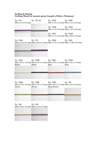
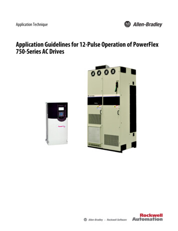
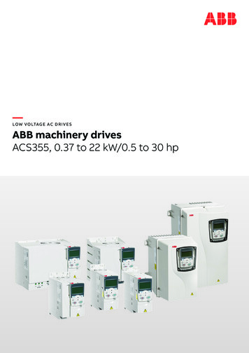
PrefaceCatalog Number Explanation20BD2P1A3AYNAEC0NNADabc1 c5defghijklmnac2c3DriveND RatingND RatingCodeType20BPowerFlex 700400V, 50 Hz InputbVoltage RatingCodeVoltagePh.Prechg.FramesB240V AC3-0 6C400V AC3-0 10D480V AC3-0 10E600V AC3-0 6F690V AC3-5 6H540V DC-N5 6, 10J650V DC-N5 6, 10N325V DC-Y5 6P540V DC-Y5 9R650V DC-Y5 9T810V DC-Y5 6W932V DC-Y5 6c1ND Rating208/240V, 60 Hz InputCode208V Amps 240V AmpsHpFrame480V, 60 Hz 27.51c402832.228102ND 999100512512512561441441506600V, 60 Hz InputRockwell Automation Publication 20B-UM002G-EN-P - July 201413
Preface20BD2P1A3AYNAEC0NNADabc1 c5defghijklmnc5fkND RatingDocumentationControl & I/OCodeTypeCodeControlI/O VoltsCodeAmps690V, 50 Hz InputkWFrameAManualAStandard 24V DC/AC05252455NNo ManualBStandard 115V AC06060555QCVector Δ24V DC08282755No Shipping Package (Internal UseOnly)DVector Δ115V ACNStandardNone0989890611911911061421421326Δ Vector Control Option utilizes DPI Only.g Frame 0 6 drives only.BrakeCodew/Brake IGBT ‡dYYeslEnclosureNNoFeedback‡ Brake IGBT is standard on Frames 0-3, optional on Frames 4-6 andnot available on Frames 7 10.CodeEnclosureAIP20, NEMA/UL Type 1F Open/Flange MountFront: IP00, NEMA/UL Type OpenBack/Heatsink: IP54, NEMA Type 12N Open/Flange MountFront: IP00, NEMA/UL Type OpenBack/Heatsink: IP54, NEMA 12CodeG Stand-Alone/Wall MountIP54, NEMA/UL Type 12NURoll-InFront: IP00, NEMA/UL Type OpenBack/Heatsink: IP54, NEMA 12Frames 8 & 9 Only0Blank Cover3LCD Display, Full Numeric KeypadJ Remote (Panel Mount), IP66, NEMA/UL Type 12 FullNumeric LCD HIMK Remote (Panel Mount), IP66, NEMA/UL Type 12 Prog. OnlyLCD HIMEncoder, 12V/5VmFuture UseYesNoNot available for Frame 3 drives or larger.nSpecial Firmware (Frames 0 6 Only)iCodeTypeEmissionAD 60 Hz MaximumCascading Fan/Pump ControlCodeCE Filter §CM ChokeAE AYesYesAX 82 Hz MaximumB#YesNoBA Pump Off (for pump jack)NNoNo§ Note: 600V class drives below 77 Amps (Frames 0-4) are declared tomeet the Low Voltage Directive. It is the responsibility of the user todetermine compliance to the EMC directive. Frames 7 10,400/480V AC drives (Voltage Rating codes "C" and "D") meet CEcertification requirements when installed per recommendations. Must be used with Vector Control option C or D (Position k). Positionsm-n are only required when custom firmware is supplied.# Only available for 208 240V Frame 0-3 drives. Available with Frames 5 6 Stand-Alone IP54 drives (Enclosure Code"G").jComm Slot141w/ResistorYHIMOperator InterfaceNoneh Only available for Frames 7 10.CodeType0Internal Braking Resistor Only available for Frame 5 & Frame 6 drives, 400 690V.eCodeCodeNetwork TypeCControlNet (Coax)DDeviceNetEEtherNet/IPNNoneRockwell Automation Publication 20B-UM002G-EN-P - July 2014
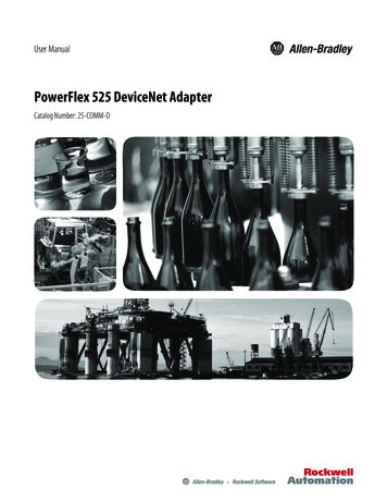
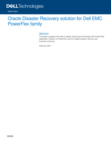
Chapter1Programming and ParametersThis chapter provides a complete listing and description of the PowerFlex 700parameters. The parameters can be programmed (viewed/edited) using an LCDHIM (Human Interface Module). As an alternative, programming can also beperformed using DriveExplorer or DriveExecutive software and a personalcomputer. See Appendix B for a brief description of the LCD HIM.About ParametersTopicPageTopicPageAbout Parameters15Communication File55How Parameters are Organized17Inputs & Outputs File59Monitor File21Applications File67Motor Control File23Pos/Spd Profile File72Speed Command File29Parameter Cross Reference – by Name77Dynamic Control File38Parameter Cross Reference – by Number80Utility File44To configure a drive to operate in a specific way, drive parameters may have to beset. Three types of parameters exist: ENUM ParametersENUM parameters allow a selection from 2 or more items. The LCDHIM will display a text message for each item. Bit ParametersBit parameters have individual bits associated with features or conditions.If the bit is 0, the feature is off or the condition is false. If the bit is 1, thefeature is on or the condition is true. Numeric ParametersThese parameters have a single numerical value (that is, 0.1 Volts).The example on the following page shows how each parameter type is presentedin this manual.Rockwell Automation Publication 20B-UM002G-EN-P - July 201415
2GroupNo.Drive . . .34Parameter Name & Description5ValuesDefault:198 [Load Frm Usr Set]Loads a previously saved set of parameter values Options:from a selected user set location in drivenonvolatile memory to active drive memory.780199“Ready”“Ready”0“User Set 1”1“User Set 2”2“User Set 3”3Read Only361 366D igitD i g al In6itD i g al In5italD i g In4itD i g al In3itD i g al In2italIn1Diagnostics216 [Dig In Status]Status of the digital inputs.6Related1FileProgramming and ParametersUTILITYChapter 1x x x x x x x x x x 0 0 0 0 0 015 14 13 12 11 10 9 8 7 6 5 4 3 2 1 01 Input Present0 Input Not Presentx ReservedTorq . . .MOTOR . . .Bit #434 [Torque Ref B Mult]FV Defines the value of the multiplier for the[Torque Ref B Sel] selection.Default:1.0Min/Max:Units:–/ 32767.00.1053No. Description1File – Lists the major parameter file category.2Group – Lists the parameter group within a file.3No. – Parameter number. Note that all parameters in the PowerFlex 700VC are 32 bit. Parameter value cannot be changed until drive is stopped.FV Parameter only displayed when [Motor Cntl Sel] is set to “4.”v6 This parameter only available with firmware version 6.002 and later.4Parameter Name & Description – Parameter name as it appears on an LCD HIM, with a brief description ofthe parameter’s function.5Values – Defines the various operating characteristics of the parameter. Three types exist.ENUMDefault:Options:Lists the value assigned at the factory. “Read Only” no default.Displays the programming selections available.BitBit:Lists the bit place holder and definition for each bit.NumericDefault:Min/Max:Units:Lists the value assigned at the f
The purpose of this manual is to provide you with the basic information needed to program and troubleshoot the PowerFlex 700 Adjustable Frequency AC Drive with Vector Control. Who Should Use this Manual? This manual is intended for qualified personnel. You must be able to program and operate Adjustable Frequency AC Drive devices.