Transcription
People Helping People Build a Safer WorldMethods of VentingPlumbing Fixtures andTraps in the 2018 IPCInstallation, Flexibility and Opportunity for SavingsLee Clifton, Senior Director of PMG Resources, Government Relations
Chapter 9 of the International PlumbingCode (IPC ) describes a variety ofmethods to vent plumbing fixtures andtraps. The methods have been laboratorytested to determine sizing and installationrequirements that provide proper ventingto a drainage system. The ventingmethods have also been field tested,establishing a long history of satisfactoryservice.In this publication, we will present thevarious approaches to venting that arepermitted in the 2018 IPC. You will findthat these venting provisions offer theinstaller and designer different paths toachieving an adequately vented system,which could result in cost savings alongwith ease of installation in different typesof construction.Three Specific Venting MethodsChapter 9 of the International Plumbing Code (IPC) describes avariety of methods to vent plumbing fixtures and traps.Section 901.2.1 of the IPC establishes that traps and trapped fixtures shall be ventedin accordance with one of the venting methods specified in this Chapter. Section 904.1requires the vent system serving each building drain to have at least one vent pipe thatextends to the outdoors.The most widely used method is commonly referred to as a conventional venting system.Table 909.1 (below) provides the maximum distance allowed for a vent in relation to thetrap. A fixture vent connected in this manner is called an individual vent. These individualvents are sized according to Section 906.2. Here we find that the vent must be at leastone-half the diameter of the drain served, but in no case less than 1¼ inches in diameter.TABLE 909.1Maximum Distance of Fixture Trap from VentSize of Trap(inches)1¼1½234Slope(inch per foot)¼¼¼1 81 8Distance from Trap(feet)5681216For SI: 1 inch 25.4 mm.Remember, the vent size is not based on the trap or fixture drain (trap arm), but the drainsize that continues downstream from the point where the vent and fixture drain connect.The drain size is determined by the fixture unit load in accordance with Tables 709.1,709.2, 710.1(1), and 710.1(2) in the IPC. Hence, if the drain size is 4 inches (102 mm),a 2-inch (51 mm) vent is required. A 3-inch (76 mm) drain would require a 1½-inch (38mm) vent. A 2-inch (51 mm), 1½-inch or 1¼-inch (38 or 31.8 mm) drain would require aminimum 1¼-inch (31.8 mm) vent, this being the minimum size allowed.Section 905.5 allows individual vents to merge with each other, as long as the connectionis made at least 6 inches above the flood-level rim of the highest fixture served. Sizing of2 Methods of Venting Plumbing Fixtures and Traps in the 2018 IPC
the vents as they connect is again based only on the required size of the drain being served.Section 906.2 requires that vents exceeding 40 feet (1016 mm) in developed length shallbe increased by one nominal pipe size for the entire developed length of the vent pipe.It is important to know that Section 904.2 states a vent stack shall be required for everydrainage stack that has five branch intervals or more. If the drainage stack is less than fivebranch intervals in height, a vent stack is not required because the pressure in the drainagestack is not likely to create a pressure differential at the trap seals in excess of 1 inch (25.4mm) of water column. When required, vent stacks are to be dry and are required to connectat or near the base of the stack served to act as a relief vent for the pressures that developin the lowest portions of the stacks.The exception in Section 904.2 wisely eliminates an unnecessary vent to a system thatalready has adequate fresh air exchange assurance. Waste stack vented systems, as coveredin Section 913, are already oversized to provide for adequate venting without the need foradditional venting.The code only requires stack vents for drainage stacks in Section 913.3 because theminimum required venting of each fixture has been accomplished when the systemcomplies with the venting methods outlined in Chapter 9. A stack vent is typically used as acollection point for vent pipes so that a single roof penetration can be made.Keep in mind that “stack vents” and “vent stacks” are distinct. See definitions in the nextsection.The example illustrates a typical vent stack compared with the special Waste Stack Venting system.Methods of Venting Plumbing Fixtures and Traps in the 2018 IPC 3
DefinitionsBranch Vent. A vent connecting one or more individual vents with a vent stack or stack vent.Circuit Vent. A vent that connects to a horizontal drainage branch and vents two traps to nomore than eight traps or trapped fixtures connected into a battery.Combination Waste and Vent System. A specially designed system of waste pipingembodying the horizontal wet venting of one or more sinks or floor drains by means of acommon waste and vent pipe adequately sized to provide free movement of air above theflow line of the drain.Common Vent. A vent connecting at the junction of two fixture drains or to a fixture branchand serving as a vent for both fixtures.Individual Vent. A pipe installed to vent a fixture trap and that connects with the ventsystem above the fixture served or terminates in the open air.Stack Vent. The extension of a soil or waste stack above the highest horizontal drainconnected to the stack.Stack Venting. A method of venting a fixture or fixtures through the soil or waste stack.Vent Stack. A vertical vent pipe installed primarily for the purpose of providing circulation ofair to and from any part of the drainage system.The developed length of individual, branch, circuit, and relief vents shall be measured fromthe farthest point of vent connection to the drainage system to the point of connection tothe vent stack, stack vent, or termination outside of the building.There are important criteria to remember when sizing a conventional venting systemcomposed of individual fixture vents, vent stacks, and stack vents. The minimum size of anindividual vent is one-half the required drain size, whereas the minimum size of the ventstacks and stack vents is one-half the size of the drain served.The sizing criteria for stack vents and vent stacks are based on three variables:1. The developed length of the vent.2. The size of the stack served by the vent.3. The total drainage fixture unit (DFU) connected to the stack.Example A:A 3-inch (76 mm) soil stack with a stack vent serving as the required vent extension to theoutdoors, connecting to a 3-inch (76 mm) building drain, must have at least a 1½-inch(38 mm) stack vent [maximum of 102 fixture units served and a maximum 25-foot (7620mm) developed length] in accordance with Section 906.1 and Table 906.1. This 1½-inch(38 mm) stack vent is the minimum size required to comply with this section because it isat least one-half the size of the building drain.4 Methods of Venting Plumbing Fixtures and Traps in the 2018 IPC
DIAMETER OFSOIL OR TABLE 906.1Size and Developed Length of Stack Vents and Vent StacksTOTAL FIXTURE MAXIMUM DEVELOPED LENGTH OF VENT (feet)aUNITS BEING DIAMETER OF VENT �﹘﹘﹘﹘940729For SI: 1 inch 25.4 mm, 1 foot 304.8 mm.aThe developed length shall be measured from the vent connection to the open air.Non-Conventional Venting MethodsProper application of these venting options cansubstantially reduce the amount of pipe and fittingsused, while still providing proper venting. Inspectorsand plumbers often overlook the opportunities affordedby these different venting methods, which have beenproven to save money and may be helpful in areas whereconventional venting methods may be difficult to install.Quality venting systems take careful planningMethods of Venting Plumbing Fixtures and Traps in the 2018 IPC 5
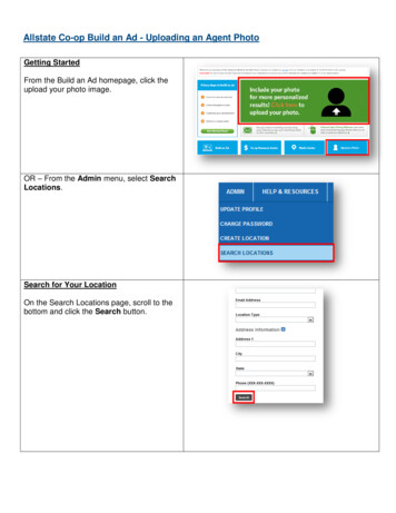
Island Fixture VentingThis is a specific method for venting an islandsink, one limited to sinks and lavatories.Residential kitchen sinks with a dishwasherwaste connection, a food waste grinder, orboth, in combination with the kitchen sinkwaste, shall be permitted.The island fixture vent shall connect to thefixture drain as required for an individual orcommon vent. The vent shall rise verticallyto above the drainage outlet of the fixturebeing vented before offsetting horizontally orvertically downward. The vent or branch ventfor multiple island fixture vents shall extendto a minimum of 6 inches (152 mm) abovethe highest island fixture being vented beforeconnecting to the outside vent terminal.The vent located below the flood level rimof the fixture being vented shall be installedas required for drainage piping in accordancewith Chapter 7, except for sizing. The ventshall be sized in accordance with Section906.2. The lowest point of the island fixturevent shall connect full size to the drainagesystem.Island Fixture VentThe connection shall be to a vertical drainpipe or to the top half of a horizontal drainpipe. Cleanouts shall be provided in the islandfixture vent to permit rodding of all ventpiping located below the flood level rim of thefixtures. Rodding in both directions shall bepermitted through a cleanout.As you can see from the diagram for thisinstallation, this venting method provides fora free flow of air where liquid is not beingtrapped in the lowest portion of the vent,because of its connection to the drain. Thismethod will work well in a crawl space orunderground application.Relief Vents—Stacks of More than10 Branch IntervalsThis venting method requires a relief ventequal to the size of the vent stack it connectswith for buildings exceeding 10 branchintervals. A relief vent must be located atevery 10 branch intervals, measured from thehighest horizontal drainage branch, and thencalculated downward to the base of the stack.The lower end of the relief vent is connectedto the soil or waste stack below the level ofThe graphic illustrates a relief vent connection.6 Methods of Venting Plumbing Fixtures and Traps in the 2018 IPC
the horizontal branch that serves thefloor level within the branch intervalrequired to have the relief vent. Thelocation of this connection is intendedto allow waste that might get into therelief vent, including condensation, toreach a waste line. This connection ismade using a wye fitting installed as adrainage fitting in order to not impairthe flow. The upper connection of therelief vent is made to the vent stackand is to be located a minimum of 3feet (914 mm) above the floor levelof the same horizontal branch. Thisconnection is made using a wye fittinginstalled in an inverted position. Therequired 3-foot (914 mm) minimumheight required is a common theme inChapter 9 and is intended to preventwaste flow from entering the vent stack.Air Admittance—Individual VentAir Admittance ValvesThe air-admittance valve (AAV) is adevice designed to allow air to enter thedrainage system to balance the pressureand prevent siphonage of the watertrap when negative pressure developsin the system. In this way, it is usedon individual vents, branch vents andcircuit vents in lieu of terminating ventsto the exterior of the structure. Stackvents and vent stacks are permitted toterminate to a stack–type air admittancevalve. The exception is for stack vents orvent stacks that serve drainage stacksexceeding six branch intervals.Because the AAV will not provide reliefof positive pressures, there are certainAir admittance valve closes and sealsinstallation requirements that areunder zero or positive pressuresspecified in the IPC to relieve positivepressure. The one open pipe ventrequired on every building drainage system in Section 918.7, Vent Required, and Section903.1, Roof Extension, mandates that at least one vent pipe shall extend to the outdoors torelieve the system’s positive pressure. Section 918.3.1 contains measures for pressure reliefby requiring the installation of a relief vent where the horizontal branch is located more thanfour branch intervals from the top of the stack.Studor ChemVent AirAdmittance Valve(Courtesy of IPS )American Society of Sanitary Engineers (ASSE) has recently developed ANSI/ASSEStandard 1049—Performance Requirements for Individual and Branch Type Air AdmittanceValves for Chemical Waste Systems. Air Admittance Valves (AAV) that are in compliancewith ANSI/ASSE 1049 and meet the requirements of Section 702.5 and tested to ASTMF1412 for chemical resistance are now allowed to serve as the vent for non-neutralizedspecial waste systems as an option to chemical waste vent piping terminating outdoors. It isquite common to see laboratory sinks that receive chemical waste located in islands in theMethods of Venting Plumbing Fixtures and Traps in the 2018 IPC 7
middle of rooms. To vent the system for thesesinks using vent piping that can only terminateoutdoors requires extensive labor and material.The use of the AAV’s will significantly reduce thecost of plumbing these laboratories.Air admittance valves shall not be located inspaces utilized as supply or return air plenums.In these locations, the negative or positivepressure conditions could adversely affect thevalves operation.Air admittance valves without an engineereddesign shall not be utilized to vent sumps ortanks of any type. The illustration below shows anexample of one manufacturer’s engineered designfor use of an air admittance valve on a sump. Thisdesign allows for positive pressure relief.Air admittance valves shall not be installedon outdoor vent terminals for the sole purposeof reducing clearances to gravity air intakes ormechanical intakes.The graphic is an example of an engineered designThe installation of air admittance valves must conformto the requirements of Section 918.3 through 918.8and the manufacturer’s instructions. Where differences occur between the provisions of the codeand the manufacturer’s instructions, the most restrictive provisions must be applied.Engineered Vent SystemsThis type of venting system is considered to be an alternative engineered design. Noticethat according to Table 919.2, which provides criteria for determining cubic feet or air flowper minute for various diameters of pipe, a vent can be as small as ½ inch in diameter.After the individual vent airflow rate is determined by the equation in Section 919.2, thesize and developed length are determined by Table 919.2. The values in the table indicatethe maximum developed length for a given pipe size and the individual vent airflow rate.Note that the engineered vent system must be designed, signed and sealed by a registereddesign professional and will need to be submitted for review by the code official inaccordance with Section 105.3 of the IPC.TABLE 919.2Minimum Diameter and Maximum Length of Individual BranchFixture Vents and Individual Fixture Header Vents for Smooth PipesINDIVIDUAL VENT AIRFLOW RATE (cubic feet per minute)DIAMETEROF VENTMaximum developed length of vent (feet)PIPE (inches) 12345678910 11 12 13 14 15 16½95 25 138543211111111¾100 88 47 30 20 15 10976543332110065 48 37 29 24 20 17 14 12 11981¼10073 62 5340321½100 9675 652For SI: 1 inch 25.4 mm, 1 cubic foot per minute 0.4719 L/s, 1 foot 304.8 mm.8 Methods of Venting Plumbing Fixtures and Traps in the 2018 IPC171272960181272654191262349201162145100
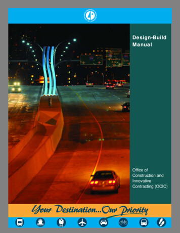
Common VentThis very simple concept allows two traps to bevented by the same vent. The two traps and theirfixture drains can be either at the same level or atdifferent levels, provided that they are on the samefloor. The following diagrams show some of thevarious approaches to common venting. The sizingof common venting is specified in Table 911.3.The arteries of civilization reach for the skiesTABLE 911.3Common Vent SizeMaximum DischargeFrom Upper FixturePipe SizeDrain (dfu)(inches)11/212421/2 to 36For SI: 1 inch 25.4 mm.Common Vent with Fixture Drains Connecting at Same LevelMethods of Venting Plumbing Fixtures and Traps in the 2018 IPC 9
(Left) Example 1: Individual Vent as Common Vent(Double Wye Used in the Vertical)(Above) Example 2: Individual Vent as Common VentExample 3: Individual Vent based on size of Common Drainage Vent10 Methods of Venting Plumbing Fixtures and Traps in the 2018 IPC
Common Vents with Fixture Drains Connecting at Same LevelWaste Stack VentThis is a very simple method of allowing a drainagestack to serve as a vent. It greatly extends the conceptof a vertical common vent, except for some specificguidelines for installation. For this system to functioneffectively there cannot be any offsets in the wastestack portion. Once the highest branch interval isconnected to the stack, the vent portion may containoffsets, provided such offsets are at least 6 inchesabove the branch interval connection. The size of thewaste stack vent is to be in accordance with Table913.4. Note for reference: the size of the stack,which is based on the total branch intervals, shall bemaintained the same size from the lowest point of thestack to the vent termination or connection to anotherapproved vent. In other words, if the fixture unit totalwould require a 3-inch-diameter (76 mm) drain perTable 913.4, then both the stack and its vent mustbe 3 inches (76 mm) in diameter with no offsets atall until at least 6 inches (152 mm) above the highestbranch interval (see diagram).These two methods of using the drain as a vent,common venting and waste stack venting, are, forthe most part, vertical in their application. Now let’sexamine Wet Venting. This method is one of the threeremaining methods of such venting that are more oftenfound in a horizontal application.Waste Stack VentMethods of Venting Plumbing Fixtures and Traps in the 2018 IPC 11
Wet VentingA fixture is said to be wet vented when it serves also to carry the discharge from fixturesconnecting into the drainage system at a higher level. The use of wet venting reduces thenumber of individual vent pipes required by a plumbing drainage system as contrasted withthe number required by a conventional system and hence reducing the cost of the ventingsystem. There are many types of venting schemes and methods allowed in the InternationalPlumbing Code (IPC). The Horizontal Wet Venting method located in Section 912.1 of theIPC is one that we will discuss today.What is a horizontal wet vent? A horizontal wet vent is a horizontal branch drain pipe thathas been increased in size larger than what is normally required by Section 710. Thisincrease in pipe size allows for alarge air space above the maximumprobable waste flow level in the pipeso as to provide for adequate ventingairflow in the same pipe as the wasteflow. Wet Venting as shown in Figure1 can be used in both vertical andhorizontal applications.The vertical method may be morecommon to plumbing installers incertain regions. However, don’tbe alarmed by what you see. Thehorizontal wet venting method isan effective way to provide a safe,sanitary system that can save thecontractor and owner time andmaterials.The fixture drain length from thewet vent is limited to the distancesshown in Table 909.1. There may bea situation where the fixture locationis at a distance that exceeds themaximum trap-to-vent distance.The code allows for any numberof individual vented fixtures of thetypes allowed for a bathroom groupto connect to the horizontal wet ventas long the total number of fixturesallowed for the bathroom groups isnot exceeded.Size of Trap(inches)1¼1½234Figure 1: Horizontal Wet Venting IllustrationTABLE 909.1Maximum Distance of Fixture Trap from VentSlopeDistance from Trap(inch per foot)(feet)¼5¼6¼81 8121 816For SI: 1 inch 25.4 mm.12 Methods of Venting Plumbing Fixtures and Traps in the 2018 IPC
Section 202 of Chapter 2 is the key to the maximum number and type of fixtures that canbe accommodated by a horizontal wet vent. The definition of Bathroom Group is a groupof fixtures consisting of a water closet, lavatory, bathtub or shower, including or excludinga bidet, an emergency floor drain or both. Such fixtures are to be located together on thesame floor level. This is done to avoid high flow velocities which could cause excessiveturbulence that might block the air space above the waste flow level. Section 912.1 allowsany combination of fixtures within two bathroom groups to be vented by a horizontal wetvent. A horizontal wet vent could have as few as two fixtures or as many as ten fixtures butnot more than two fixtures of any type can be connected to the system. Each wet ventedfixture drain shall connect independently to the horizontal wet vent. This is done to protectthe function of each fixture, assuring that one fixture will not influence another’s operation.The dry vent, the vent that continues upward from the wet vent to the point of terminationof connection to another vent, shall be either an individual vent or a common vent for anybathroom group fixture, except an emergency floor drain. Where the dry vent connects toa water closet fixture drain, the drain shall connect horizontally to the horizontal wet ventsystem. Not more than one wet vented fixture drain shall discharge upstream of the dryvented fixture drain connection.Vertical wet vented systems arerequired to have the water closets asthe most downstream fixture. This isnot the case in horizontal wet venting.The dry vent must be sized inaccordance with Section 906.2.Remember, though, that in this case,the drain served is going to be theentire wet vented section. It will needto be at least one-half the diameterof the largest section of pipe in thesystem. The wet-vented section itselfis sized per Table 912.3. Keep inmind that any additional fixturesoutside of the wet vent that are tobe drained into the same branchmust be connected to the branchdownstream of the wet vent. Becausethe wet vent serves as a drain, thetype of fittings used must be inaccordance with the drainage patternshown in Table 706.IPC Venting Methods Save Resources and Lowers CostWhile Protecting the Health of the NationTABLE 912.3Wet Vent SizeWet Vent Pipe Size(inches)11/2221/23Drainage Fixture Load(dfu)14612For SI: 1 inch 25.4 mm.Methods of Venting Plumbing Fixtures and Traps in the 2018 IPC 13
Circuit VentingThe International Plumbing Code (IPC) has a variety of methods that can be used to ventplumbing fixtures and traps. Circuit venting is one of these methods and it has beenlaboratory and field tested, establishing a long history of satisfactory service. Extensiveresearch into the performance of circuit vented systems was conducted at the State Universityof Iowa. The research concluded that the single vent for the eight fixtures provided thenecessary protection of the trap seal. Circuit venting was included in Roy B. Hunter’s researchat the National Bureau of Standards and reported in BMS 66. The venting method has longbeen recognized by the plumbing community and is included in the American Society ofPlumbing Engineers Data Book. The principle of circuit venting is that the flow of drainagenever exceeds a half-full flow condition. The air for venting the fixtures circulates in the tophalf of the horizontal branch drain pipe. The flow velocity in the horizontal branch is slow andnon-turbulent, thereby preventing pressure differentials from affecting the connecting fixtures.The circuit-vented fixtures must connect to the circuit-vented branch in the horizontal plane tolimit the amount of turbulence created by fixture discharge.Size of Trap(inches)1¼1½234TABLE 909.1Maximum Distance of Fixture Trap from VentSlopeDistance from Trap(inch per foot)(feet)¼5¼6¼81 8121 816For SI: 1 inch 25.4 mm.Sizing a Circuit Vent System14 Methods of Venting Plumbing Fixtures and Traps in the 2018 IPC
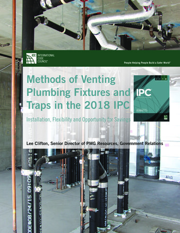
The Circuit Venting method is similar to wet venting except that it allows you to combine atotal of eight fixtures on a single floor that are not limited to the two bathroom groups. Itmight be easier to explain by examining how circuit venting differs from wet venting. Thefixture drains shall connect horizontally to the horizontal branch being circuit vented. Again,the fixture drains are limited in length to those shown in Table 909.1. Because circuitventing is only to be used on horizontal applications as opposed to wet venting, which canbe both horizontal and vertical installations, the maximum slope for a circuit vent is 1 unitin 12 units horizontally, or 8-percent slope. The entire length of the circuit vent portion ofthe horizontal branch shall be sized for the total drainage discharge to the branch. There isnot a unique sizing table for circuit venting as there is for wet venting or common venting.The circuit vent connection must be located between the two uppermost fixture drains andshall connect to the horizontal branch. It cannot serve as a drain for other fixtures—it istruly a dry vent. Where a circuit vent consists of four or more water closets and dischargesinto a drainage stack that also receives the discharge of upper horizontal branches, a reliefvent shall be connected to the horizontal branch ahead of the connection to the drainagestack and after the most downstream fixture drain of the circuit vent (see Figure 2).Additional fixture drains may be connected with the circuit-vented branch, but they needto be vented by meansother than the circuitvent, and the fixture unitvalues would be addedto the total fixtureunit discharge into thehorizontal branch. Suchfixtures must also belocated on the samefloor as the circuit ventto which they connect.Where the relief ventreceives the dischargeof other fixtures, themaximum dischargeallowed is 4 drainagefixture units.Figure 2: Circuit Vent with Relief Vent ConnectionMethods of Venting Plumbing Fixtures and Traps in the 2018 IPC 15
Combination Waste and Vent SystemThis system is based on the same premise as the circuit-vented system. Most plumbingcodes place arbitrary restrictions on combination drain (waste) and vent systems becausethe system appears too good to be true. The performance of the combination waste andvent system was verified in tests conducted at the Stevens Institute of Technology. Ifsized according to Table 915.2.2 in the IPC, the study concluded that the distance froma trap does not have to be limited in length. This is a horizontal wet vent system limitedto floor drains, standpipes, sinks and lavatories for the purpose of venting, except that avertical riser, not to exceed 8 feet in length, may be used to connect a fixture drain to thehorizontal combination drain and vent system. Again, the idea here is that the top half ofthe horizontal drain acts as a vent. As long as both the horizontal drain and vent system andthe maximum 8-foot riser to a fixture drain are sized in accordance with Table 915.2.2, theflow of free air will be sufficient for the propped design.DiameterPipe(inches)22½3456TABLE 915.2.2Size of Combination Waste and Vent PipeMaximum Number of Drainage Fixture Units(dfu)Connection to a horizontalConnection to a building drainbranch or stackor building sub-drain3462612312050160250360575For SI: 1 inch 25.4 mm.Of course, to get that free flow ofair, a vent to the atmosphere mustbe provided. The vent, which mustbe sized for the total drainagefixture load of the combinationdrain and vent system per Section906.2, can be located anywhereon the system and must risevertically at least 6 inches beforeoffsetting. This type of system isunique in that a branch that isalready vented can accept a fixturedrain under this combination drainand vent method (see Figure 3).Remember, too, that this type ofventing procedure is dependent onadequate sizing and maintaininga horizontal installation. For thisreason, the horizontal portion mustnot exceed a slope of one-half unitvertical in 12 units horizontal, or4-percent slope. The horizontallength of a combination waste andvent system shall be unlimited.16 Methods of Venting Plumbing Fixtures and Traps in the 2018 IPCFigure 3
The IPC continues to emphasize both prescriptive- and performance-related provisions. Aproven venting system method was added in the 2012 IPC that now compliments the mostextensive collection of venting options in the world.Single Stack Vent SystemThe Single Stack Vent System was introduced into the IPC in the 2012 Edition and is basedon a drainage stack system in the City of Philadelphia (Pennsylvania) Plumbing Code whichhas been used successfully in many multi-story and high-rise buildings for over 100 years. ThePhiladelphia System is described in Volume 2, Chapter 3 of the American Society of PlumbingEngineers (ASPE) Data Book. The Philadelphia or ‘one pipe’ system refers to the use of onedrainage stack instead of having separate drainage and vent stacks The Philadelphia systemsuccessfully utilizes “S” traps for fixture traps located above the floor and within a specifieddistance from the stack. However, because the IPC prohibits the use of S traps, the SingleStack Vent System in the IPC utilizes an oversized vertical pipe from its connection at theend of the fixture trap’s fixture drain (also known by some tradesmen as a ‘trap arm’) to thehorizontal drainage piping of the system. This is the same concept utilized in combinationwaste and vent systems for fixtures that are located above the floor. The oversized vertical pipeeliminates any possibility of siphoning of a fixture trap as the waste volume entering the verticalpipe could not possibly block the venting air space in the vertical pipe.In a Single Stack Vent System the drainage stack serves as botha single-stack drainage and vent system. The drainage stack andbranch piping are consid
common waste and vent pipe adequately sized to provide free movement of air above the flow line of the drain. Common Vent. A vent connecting at the junction of two fixture drains or to a fixture branch and serving as a vent for both fixtures. Individual Vent. A pipe installed to vent a fixture trap and that connects with the vent