Transcription
Valve terminalMPA-SPneumaticcomponentsdescriptionValve terminal withMPA-S pneumaticsType:MPA-FBMPA-CPIMPA-MPM- andMPA-ASI- 5342411309f[8028624]
MPA-STranslation of the original instructionsP.BE-MPA-ENAS-Interface is a registered trademark of its respective trademark holder in certain countries.Identification of hazards and instructions on how to prevent them:WarningHazards that can cause death or serious injuries.CautionHazards that can cause minor injuries or serious material damage.Other symbols:NoteMaterial damage or loss of function.Recommendations, tips, references to other documentation.Essential or useful accessories.Information on environmentally sound usage.Text designations: Activities that may be carried out in any order.1. Activities that should be carried out in the order stated.– General lists.2Festo – P.BE-MPA-EN – 1309f –
MPA-STable of contents – MPA-S1Safety and requirements for product use . . . . . . . . . . . . . . . . . . . . . . . . . . . . . . . . . . . . . .91.1Safety . . . . . . . . . . . . . . . . . . . . . . . . . . . . . . . . . . . . . . . . . . . . . . . . . . . . . . . . . . . . . . . . . .1.1.1General safety instructions . . . . . . . . . . . . . . . . . . . . . . . . . . . . . . . . . . . . . . . . .1.1.2Intended use . . . . . . . . . . . . . . . . . . . . . . . . . . . . . . . . . . . . . . . . . . . . . . . . . . . . .Requirements for product use . . . . . . . . . . . . . . . . . . . . . . . . . . . . . . . . . . . . . . . . . . . . . . .1.2.1Technical requirements . . . . . . . . . . . . . . . . . . . . . . . . . . . . . . . . . . . . . . . . . . . .1.2.2Qualification of the specialists (requirements for the personnel) . . . . . . . . . . . .1.2.3Range of application and certifications . . . . . . . . . . . . . . . . . . . . . . . . . . . . . . . .1.2.4Instructions on this description . . . . . . . . . . . . . . . . . . . . . . . . . . . . . . . . . . . . . .10101011111111122Overview . . . . . . . . . . . . . . . . . . . . . . . . . . . . . . . . . . . . . . . . . . . . . . . . . . . . . . . . . . . . . . . .132.12.22.32.4The MPA-S valve terminal . . . . . . . . . . . . . . . . . . . . . . . . . . . . . . . . . . . . . . . . . . . . . . . . . . .Overview of variants . . . . . . . . . . . . . . . . . . . . . . . . . . . . . . . . . . . . . . . . . . . . . . . . . . . . . . .Valve terminal design . . . . . . . . . . . . . . . . . . . . . . . . . . . . . . . . . . . . . . . . . . . . . . . . . . . . . .Description of components . . . . . . . . . . . . . . . . . . . . . . . . . . . . . . . . . . . . . . . . . . . . . . . . . .2.4.1Sizes . . . . . . . . . . . . . . . . . . . . . . . . . . . . . . . . . . . . . . . . . . . . . . . . . . . . . . . . . . .2.4.2Valves . . . . . . . . . . . . . . . . . . . . . . . . . . . . . . . . . . . . . . . . . . . . . . . . . . . . . . . . . .2.4.3Proportional pressure regulator . . . . . . . . . . . . . . . . . . . . . . . . . . . . . . . . . . . . .2.4.4Pressure sensor plate . . . . . . . . . . . . . . . . . . . . . . . . . . . . . . . . . . . . . . . . . . . . . .2.4.5Pneumatic air supply plate . . . . . . . . . . . . . . . . . . . . . . . . . . . . . . . . . . . . . . . . . .2.4.6Electrical air supply plate . . . . . . . . . . . . . . . . . . . . . . . . . . . . . . . . . . . . . . . . . . .2.4.7Pressure zone separation . . . . . . . . . . . . . . . . . . . . . . . . . . . . . . . . . . . . . . . . . . .2.4.8Vertical stacking . . . . . . . . . . . . . . . . . . . . . . . . . . . . . . . . . . . . . . . . . . . . . . . . . .Operation and connection elements . . . . . . . . . . . . . . . . . . . . . . . . . . . . . . . . . . . . . . . . . . .2.5.1Manual override (MO) . . . . . . . . . . . . . . . . . . . . . . . . . . . . . . . . . . . . . . . . . . . . .2.5.2Operating and connection elements of the pressure regulator plates . . . . . . . .2.5.3Multi-pin connecting components . . . . . . . . . . . . . . . . . . . . . . . . . . . . . . . . . . . .Display components . . . . . . . . . . . . . . . . . . . . . . . . . . . . . . . . . . . . . . . . . . . . . . . . . . . . . . .2.6.1Pressure sensor plate . . . . . . . . . . . . . . . . . . . . . . . . . . . . . . . . . . . . . . . . . . . . . .2.6.2Proportional pressure regulator . . . . . . . . . . . . . . . . . . . . . . . . . . . . . . . . . . . . .2.6.3Proportional-pressure regulator with LCD display . . . . . . . . . . . . . . . . . . . . . . . .14151920242426272727283137383940414344453Mounting and installation . . . . . . . . . . . . . . . . . . . . . . . . . . . . . . . . . . . . . . . . . . . . . . . . . .473.1General instructions on mounting and dismantling . . . . . . . . . . . . . . . . . . . . . . . . . . . . . . .481.22.52.6Festo – P.BE-MPA-EN – 1309f – English3
MPA-S3.2Mounting variants . . . . . . . . . . . . . . . . . . . . . . . . . . . . . . . . . . . . . . . . . . . . . . . . . . . . . . . . .3.2.1Mounting/dismounting on H-rails . . . . . . . . . . . . . . . . . . . . . . . . . . . . . . . . . . . .3.2.2Mounting/dismounting on walls . . . . . . . . . . . . . . . . . . . . . . . . . . . . . . . . . . . . .3.2.3Standard fastening points of the valve terminal . . . . . . . . . . . . . . . . . . . . . . . . .3.2.4Additional fastening of the valve terminal . . . . . . . . . . . . . . . . . . . . . . . . . . . . . .Mounting/dismounting the inscription label holder . . . . . . . . . . . . . . . . . . . . . . . . . . . . . .Compressed air preparation . . . . . . . . . . . . . . . . . . . . . . . . . . . . . . . . . . . . . . . . . . . . . . . . .3.4.1Operation with unlubricated compressed air . . . . . . . . . . . . . . . . . . . . . . . . . . .3.4.2Operation with lubricated compressed air . . . . . . . . . . . . . . . . . . . . . . . . . . . . .General instructions on installation . . . . . . . . . . . . . . . . . . . . . . . . . . . . . . . . . . . . . . . . . . .Connecting the MPA-S valve terminal . . . . . . . . . . . . . . . . . . . . . . . . . . . . . . . . . . . . . . . . . .3.6.1Pilot control (pilot air supply) . . . . . . . . . . . . . . . . . . . . . . . . . . . . . . . . . . . . . . . .3.6.2MPA-S valve terminal with pressure zone separation . . . . . . . . . . . . . . . . . . . . .3.6.3Operation of the MPA-S. valve terminal with reversible pressure regulators . .3.6.4Setting the pressure regulator . . . . . . . . . . . . . . . . . . . . . . . . . . . . . . . . . . . . . . .3.6.5Controller with rigid threaded connection (MPA1) . . . . . . . . . . . . . . . . . . . . . . .3.6.6Vacuum/low-pressure operation . . . . . . . . . . . . . . . . . . . . . . . . . . . . . . . . . . . . .3.6.7Connecting the pneumatic lines . . . . . . . . . . . . . . . . . . . . . . . . . . . . . . . . . . . . . .Installation of the tubing lines . . . . . . . . . . . . . . . . . . . . . . . . . . . . . . . . . . . . . . . . . . . . . . .3.7.1Connecting . . . . . . . . . . . . . . . . . . . . . . . . . . . . . . . . . . . . . . . . . . . . . . . . . . . . . .3.7.2Removing . . . . . . . . . . . . . . . . . . . . . . . . . . . . . . . . . . . . . . . . . . . . . . . . . . . . . . .3.7.3Common pneumatic lines . . . . . . . . . . . . . . . . . . . . . . . . . . . . . . . . . . . . . . . . . . .Connecting the electric cables . . . . . . . . . . . . . . . . . . . . . . . . . . . . . . . . . . . . . . . . . . . . . . .3.8.1Load voltage supply via electrical supply plate (only for MPA-S valve terminal withCPX terminal or CPI interface) . . . . . . . . . . . . . . . . . . . . . . . . . . . . . . . . . . . . . . .3.8.2Earthing the MPA-S valve terminal . . . . . . . . . . . . . . . . . . . . . . . . . . . . . . . . . . . .Address assignment of the valves . . . . . . . . . . . . . . . . . . . . . . . . . . . . . . . . . . . . . . . . . . . .3.9.1MPA-S valve terminal with CPX terminal . . . . . . . . . . . . . . . . . . . . . . . . . . . . . . .3.9.2MPA-S valve terminal with CPI module or AS-interface . . . . . . . . . . . . . . . . . . . .3.9.3MPA-S valve terminal with multi-pin plug connection . . . . . . . . . . . . . . . . . . . . .7476787879804Commissioning . . . . . . . . . . . . . . . . . . . . . . . . . . . . . . . . . . . . . . . . . . . . . . . . . . . . . . . . . . .834.1Prior to commissioning . . . . . . . . . . . . . . . . . . . . . . . . . . . . . . . . . . . . . . . . . . . . . . . . . . . . .4.1.1Pressure build-up in the overall supply . . . . . . . . . . . . . . . . . . . . . . . . . . . . . . . .Manual override (MO) . . . . . . . . . . . . . . . . . . . . . . . . . . . . . . . . . . . . . . . . . . . . . . . . . . . . . .Testing the valves and the valve/actuator combination . . . . . . . . . . . . . . . . . . . . . . . . . . . .Mounting/removing the manual override cover cap (optional) . . . . . . . . . . . . . . . . . . . . . .4.4.1Mounting . . . . . . . . . . . . . . . . . . . . . . . . . . . . . . . . . . . . . . . . . . . . . . . . . . . . . . .4.4.2Dismounting . . . . . . . . . . . . . . . . . . . . . . . . . . . . . . . . . . . . . . . . . . . . . . . . . . . . .LED display of the valves . . . . . . . . . . . . . . . . . . . . . . . . . . . . . . . . . . . . . . . . . . . . . . . . . . . .4.5.1MPA-S valve terminal with CPX terminal or CPI connection . . . . . . . . . . . . . . . . .4.5.2MPA-S valve terminal with multi-pin plug connection or AS-interface . . . . . . . .Commissioning instructions for the proportional pressure regulator . . . . . . . . . . . . . . . . 727374Festo – P.BE-MPA-EN – 1309f – English
MPA-S4.7Error handling . . . . . . . . . . . . . . . . . . . . . . . . . . . . . . . . . . . . . . . . . . . . . . . . . . . . . . . . . . . .4.7.1Impairment of functions . . . . . . . . . . . . . . . . . . . . . . . . . . . . . . . . . . . . . . . . . . . .4.7.2Operating statuses of the pneumatic system . . . . . . . . . . . . . . . . . . . . . . . . . . .9797985Conversion and maintenance . . . . . . . . . . . . . . . . . . . . . . . . . . . . . . . . . . . . . . . . . . . . . . . 5General instructions . . . . . . . . . . . . . . . . . . . . . . . . . . . . . . . . . . . . . . . . . . . . . . . . . . . . . . .Dismantling the MPA-S valve terminal . . . . . . . . . . . . . . . . . . . . . . . . . . . . . . . . . . . . . . . . .5.2.1Disconnect the electrical connections . . . . . . . . . . . . . . . . . . . . . . . . . . . . . . . . .5.2.2Disconnecting the pneumatic connections . . . . . . . . . . . . . . . . . . . . . . . . . . . . .5.2.3Dismantling the MPA-S valve terminal . . . . . . . . . . . . . . . . . . . . . . . . . . . . . . . . .Maintenance of the MPA-S valve terminal . . . . . . . . . . . . . . . . . . . . . . . . . . . . . . . . . . . . . .5.3.1Service and maintenance measures to be executed regularly . . . . . . . . . . . . . .5.3.2Cleaning the flat plate silencer . . . . . . . . . . . . . . . . . . . . . . . . . . . . . . . . . . . . . . .5.3.3Replace the flat plate silencer or the exhaust plate . . . . . . . . . . . . . . . . . . . . . .5.3.4Replacing valves or cover plates . . . . . . . . . . . . . . . . . . . . . . . . . . . . . . . . . . . . .5.3.5Replacing the proportional pressure regulator . . . . . . . . . . . . . . . . . . . . . . . . . .5.3.6Replacing electronics modules . . . . . . . . . . . . . . . . . . . . . . . . . . . . . . . . . . . . . .5.3.7Replacing the sub-base, supply plate or MPA-S end plate . . . . . . . . . . . . . . . . .5.3.8Replacing interlinking boards – MPA-S with multi-pin plug connectionor AS interface . . . . . . . . . . . . . . . . . . . . . . . . . . . . . . . . . . . . . . . . . . . . . . . . . . .Conversion of the MPA-S valve terminal . . . . . . . . . . . . . . . . . . . . . . . . . . . . . . . . . . . . . . . .5.4.1Conversion to internal or external pilot air supply . . . . . . . . . . . . . . . . . . . . . . . .5.4.2Conversion of the MPA-S valve terminal to different pressure zones . . . . . . . . .5.4.3Adding valve positions . . . . . . . . . . . . . . . . . . . . . . . . . . . . . . . . . . . . . . . . . . . . .5.4.4Adding an electric supply plate (only for MPA-S valve terminal with CPX terminalor CPI interface) . . . . . . . . . . . . . . . . . . . . . . . . . . . . . . . . . . . . . . . . . . . . . . . . . .5.4.5Adding a pressure sensor plate . . . . . . . . . . . . . . . . . . . . . . . . . . . . . . . . . . . . . .5.4.6Adding a proportional pressure regulator . . . . . . . . . . . . . . . . . . . . . . . . . . . . . .De-commissioning and disposal . . . . . . . . . . . . . . . . . . . . . . . . . . . . . . . . . . . . . . . . . . . . . .ATechnical appendix . . . . . . . . . . . . . . . . . . . . . . . . . . . . . . . . . . . . . . . . . . . . . . . . . . . . . . . .129A.1Technical data . . . . . . . . . . . . . . . . . . . . . . . . . . . . . . . . . . . . . . . . . . . . . . . . . . . . . . . . . . . .A.1.1General . . . . . . . . . . . . . . . . . . . . . . . . . . . . . . . . . . . . . . . . . . . . . . . . . . . . . . . . .A.1.2Operating and environmental conditions . . . . . . . . . . . . . . . . . . . . . . . . . . . . . . .A.1.3Pneumatics . . . . . . . . . . . . . . . . . . . . . . . . . . . . . . . . . . . . . . . . . . . . . . . . . . . . . .A.1.4Electrical data . . . . . . . . . . . . . . . . . . . . . . . . . . . . . . . . . . . . . . . . . . . . . . . . . . . .A.1.5Product key . . . . . . . . . . . . . . . . . . . . . . . . . . . . . . . . . . . . . . . . . . . . . . . . . . . . . .Festo accessories . . . . . . . . . . . . . . . . . . . . . . . . . . . . . . . . . . . . . . . . . . . . . . . . . . . . . . . . .1301301321351481501505.35.4A.2Festo – P.BE-MPA-EN – 1309f – English1141161161201221251271271285
MPA-SBSupplementary component overview . . . . . . . . . . . . . . . . . . . . . . . . . . . . . . . . . . . . . . . . .151B.1B.2Overview of valve position components . . . . . . . . . . . . . . . . . . . . . . . . . . . . . . . . . . . . . . . .Separating the MPA-S valve terminal from the CPX terminal . . . . . . . . . . . . . . . . . . . . . . . .B.2.1Dismantling . . . . . . . . . . . . . . . . . . . . . . . . . . . . . . . . . . . . . . . . . . . . . . . . . . . . .B.2.2Mounting . . . . . . . . . . . . . . . . . . . . . . . . . . . . . . . . . . . . . . . . . . . . . . . . . . . . . . .152161162163CGlossary . . . . . . . . . . . . . . . . . . . . . . . . . . . . . . . . . . . . . . . . . . . . . . . . . . . . . . . . . . . . . . . .1656Festo – P.BE-MPA-EN – 1309f – English
MPA-SInstructions on this documentationThis documentation serves the purpose of ensuring safe work with the MPS-S valve terminal and contains specific information on mounting, installing, commissioning, servicing and converting the MPA-Svalve terminal. It covers only the description of the pneumatic components.ServicePlease consult your regional Festo contact if you have any technical problems.Festo – P.BE-MPA-EN – 1309f – English7
MPA-SDocumentationInformation on the electrical/electronic components can be found in the following documentation:Design of the valve terminalDocumentationMPA-S with CPX terminalDescription for the respective CPX module(You will find an overview of the descriptions in the systemdescription of your CPX terminal.)respective package insertMPA-S with– multi-pin plug connection– CPI interface– AS-interfaceTab. 18Documentation for the MPA-S valve terminalFesto – P.BE-MPA-EN – 1309f – English
111.11.2Safety and requirements for product useSafety and requirements for product useSafety . . . . . . . . . . . . . . . . . . . . . . . . . . . . . . . . . . . . . . . . . . . . . . . . . . . . . . . . . . . . . . . . . .1.1.1General safety instructions . . . . . . . . . . . . . . . . . . . . . . . . . . . . . . . . . . . . . . . . .1.1.2Intended use . . . . . . . . . . . . . . . . . . . . . . . . . . . . . . . . . . . . . . . . . . . . . . . . . . . . .Requirements for product use . . . . . . . . . . . . . . . . . . . . . . . . . . . . . . . . . . . . . . . . . . . . . . .1.2.1Technical requirements . . . . . . . . . . . . . . . . . . . . . . . . . . . . . . . . . . . . . . . . . . . .1.2.2Qualification of the specialists (requirements for the personnel) . . . . . . . . . . . .1.2.3Range of application and certifications . . . . . . . . . . . . . . . . . . . . . . . . . . . . . . . .1.2.4Instructions on this description . . . . . . . . . . . . . . . . . . . . . . . . . . . . . . . . . . . . . .Festo – P.BE-MPA-EN – 1309f – English10101011111111129
1Safety and requirements for product use1.1Safety1.1.1General safety instructionsNoteDamage to the product from incorrect handling. Switch off the supply voltage before mounting and installation work. Switch on supply voltage only when mounting and installation work are completely finished. Never unplug or plug in a product when powered! Observe the handling specifications for electrostatically sensitive devices.1.1.2Intended useThe valve terminal MPA-S is intended for installation in machines or automated systems and may beused only as follows:– in excellent technical condition,– in original status without unauthorised modifications,– within the limits of the product defined by the technical data ( Appendix A),– in an industrial environment.The limit values specified for pressures, temperatures, electrical data, torques etc. must be observed.Comply with the legal rules and regulations and standards, rules of the testing organisations and insurance companies and national specifications applicable for the location.NoteIn the event of damage caused by unauthorised manipulation or other than intendeduse, the guarantee is invalidated and the manufacturer is not liable for damages.10Festo – P.BE-MPA-EN – 1309f – English
11.2Safety and requirements for product useRequirements for product use Make this documentation available to the design engineer, installer and personnel responsible forcommissioning the machine or system in which this product is used. Make sure that the specifications of the documentation are always complied with. Also consider thedocumentation for the other components and modules. Take into consideration the legal regulations applicable for the destination, as well as:– regulations and standards,– regulations of the testing organizations and insurers,– national specifications.1.2.1Technical requirementsGeneral conditions for the correct and safe use of the product, which must be observed at all times: Comply with the connection and environmental conditions specified in the technical data of theproduct ( appendix A) and of all connected components.Only compliance with the limit values or load limits permits operation of the product in accordancewith the relevant safety regulations. Observe the instructions and warnings in this documentation.1.2.2Qualification of the specialists (requirements for the personnel)The product may only be commissioned by trained control and automation technology professionals,who are familiar with:– installation and operation of control and automation systems,– the applicable regulations for accident protection and industrial safety, and– the documentation for the product.1.2.3Range of application and certificationsStandards and test values which the product complies with and fulfils can be found in the “Technicaldata” section ( Appendix A). The product-relevant EU directives can be found in the declaration ofconformity.Certificates and the declaration of conformity for this product can be found atwww.festo.com.The product fulfils the requirements of EU directives and is marked with the CE certification.Festo – P.BE-MPA-EN – 1309f – English11
1Safety and requirements for product useCertain configurations of the product have been certified by Underwriters Laboratories Inc. (UL) for theUSA and Canada. These configurations bear the following mark:UL Recognized Component Mark for Canada and the United StatesOnly for connection to a NEC Class 2 supply.Raccorder Uniquement a un circuit de Classe 2.NoteObserve the following if the UL requirements are to be complied with in your application:– Rules for observing the UL certification can be found in the separate UL-specificdocumentation. The relevant technical data listed there also apply here.– The technical data in this documentation may show values deviating from this.1.2.4Instructions on this descriptionThis description contains specific information on mounting, installing, commissioning, servicing andconverting the MPA-S valve terminal. It includes only the description of the pneumatic components.Information on the electrical/electronic components can be found for:– MPA-S with CPX terminal:in the description on the respective CPX module. An overview is provided in the system description of your CPX terminal, in the “Descriptions of the CPX terminal” table.– MPA-S with multi-pin plug connection, CPI interface, AS-interface:in the respective package insert12Festo – P.BE-MPA-EN – 1309f – English
222.12.22.32.42.52.6OverviewOverviewThe MPA-S valve terminal . . . . . . . . . . . . . . . . . . . . . . . . . . . . . . . . . . . . . . . . . . . . . . . . . . .Overview of variants . . . . . . . . . . . . . . . . . . . . . . . . . . . . . . . . . . . . . . . . . . . . . . . . . . . . . . .Valve terminal design . . . . . . . . . . . . . . . . . . . . . . . . . . . . . . . . . . . . . . . . . . . . . . . . . . . . . .Description of components . . . . . . . . . . . . . . . . . . . . . . . . . . . . . . . . . . . . . . . . . . . . . . . . . .2.4.1Sizes . . . . . . . . . . . . . . . . . . . . . . . . . . . . . . . . . . . . . . . . . . . . . . . . . . . . . . . . . . .2.4.2Valves . . . . . . . . . . . . . . . . . . . . . . . . . . . . . . . . . . . . . . . . . . . . . . . . . . . . . . . . . .2.4.3Proportional pressure regulator . . . . . . . . . . . . . . . . . . . . . . . . . . . . . . . . . . . . .2.4.4Pressure sensor plate . . . . . . . . . . . . . . . . . . . . . . . . . . . . . . . . . . . . . . . . . . . . . .2.4.5Pneumatic air supply plate . . . . . . . . . . . . . . . . . . . . . . . . . . . . . . . . . . . . . . . . . .2.4.6Electrical air supply plate . . . . . . . . . . . . . . . . . . . . . . . . . . . . . . . . . . . . . . . . . . .2.4.7Pressure zone separation . . . . . . . . . . . . . . . . . . . . . . . . . . . . . . . . . . . . . . . . . . .2.4.8Vertical stacking . . . . . . . . . . . . . . . . . . . . . . . . . . . . . . . . . . . . . . . . . . . . . . . . . .Operation and connection elements . . . . . . . . . . . . . . . . . . . . . . . . . . . . . . . . . . . . . . . . . . .2.5.1Manual override (MO) . . . . . . . . . . . . . . . . . . . . . . . . . . . . . . . . . . . . . . . . . . . . .2.5.2Operating and connection elements of the pressure regulator plates . . . . . . . .2.5.3Multi-pin connecting components . . . . . . . . . . . . . . . . . . . . . . . . . . . . . . . . . . . .Display components . . . . . . . . . . . . . . . . . . . . . . . . . . . . . . . . . . . . . . . . . . . . . . . . . . . . . . .2.6.1Pressure sensor plate . . . . . . . . . . . . . . . . . . . . . . . . . . . . . . . . . . . . . . . . . . . . . .2.6.2Proportional pressure regulator . . . . . . . . . . . . . . . . . . . . . . . . . . . . . . . . . . . . .2.6.3Proportional-pressure regulator with LCD display . . . . . . . . . . . . . . . . . . . . . . . .Festo – P.BE-MPA-EN – 1309f – English141519202424262727272831373839404143444513
22.1OverviewThe MPA-S valve terminalFesto supports your automation tasks at machine level with the MPA-S valve terminal. The modularstructure of the MPA-S valve terminal enables you to match this valve terminal optimally to your machine or system.The valve terminal pneumatics establish the following connection:– Common ducts for supply and exhaust air– Electric signals of all solenoid coils.Working lines (2) and (4) are provided for each valve position on the individual pneumatic modules. Thevalves are supplied with compressed air (operating pressure and pilot pressure) via the common channels and connections in the basic components. The exhaust air (from the valves and the pilot exhaustair) is also exhausted via these common channels. Further components for pressure supply are alsoavailable, e.g. in order to supply pressure zones.The MPA-S valve terminal is equipped with current reduction. The nominal current of the solenoid coilsis then reduced after the high-current phase (switching operation). The current reduction offers thefollowing advantages:– The MPA-S valve terminal has a lower energy consumption– The power unit for the voltage supply to the MPA-S valve terminal can be designed more economically depending on the individual case– The solenoid coils have lower power loss and produce less waste heat.14Festo – P.BE-MPA-EN – 1309f – English
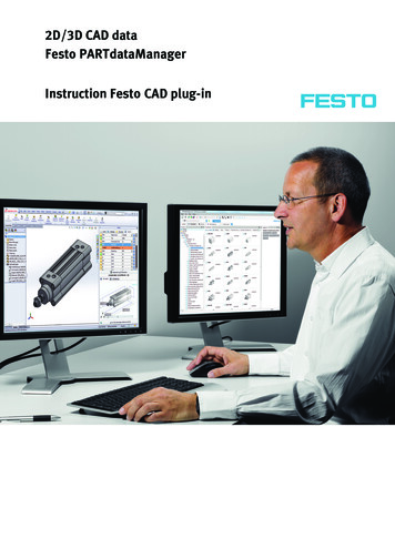
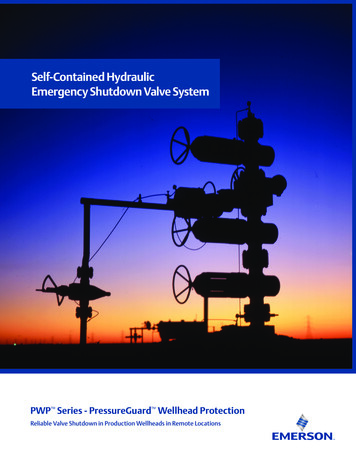
2Overview2.2Overview of variantsValve terminal with CPX terminalThis variant of the MPA-S valve terminal is available in the following grades:MPA-S valve terminal with CPX terminalNumber of valve positions 1)Load voltage supply for the valves via .– CPX terminal 2)– CPX terminal and electric air supply plate (MPA) 3)MPA14, 8, 12 324, 8, 12 641)Two solenoid coils can be controlled per valve position.2)A max. of 64 solenoid coils can be supplied.3)A max. of 128 solenoid coils can be supplied.Tab. 2.1Number of valve locations of the MPA-S valve terminal with CPX terminalFig. 2.1MPA-S valve terminal with CPX terminalFesto – P.BE-MPA-EN – 1309f – EnglishMPA22, 4, 6 162, 4, 6 3215
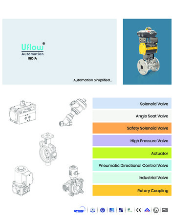
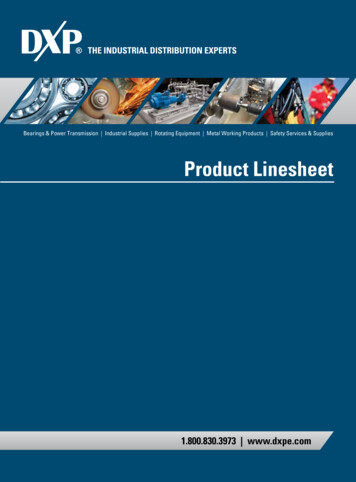
2OverviewMPA-S valve terminal with CPI interfaceThis variant of the MPA-S valve terminal is available in the following grades:MPA-S valve terminal with CPI interfaceNumber of valve positions 1)Load voltage supply for the valves via .CPI interface 2)CPI interface and electric supply plate (MPA) 3)MPA14, 8 124, 8, 12 161)Two solenoid coils can be controlled per valve position.2)A max. of 24 solenoid coils can be supplied.3)A max. of 32 solenoid coils can be supplied.Tab. 2.2Number of valve positions of the MPA-S valve terminal with CPI interfaceFig. 2.2MPA-S valve terminal with CPI interface16MPA22, 4, 6 122, 4, 6 16Festo – P.BE-MPA-EN – 1309f – English
2OverviewValve terminal MPA-S with multi-pin connectionThis variant of the MPA-S valve terminal is available in the following grades:Number of valve positions 1)MPA14, 8, 12 241)MPA22, 4, 6, 24A maximum of 24 solenoid coils can be actuated. The electrical connection of the solenoid coils is made centrally via the multi-pinplug.Tab. 2.3Number of valve positions of the valve terminal MPA-S with multi-pin plug connectionFig. 2.3Valve terminal MPA-S with multi-pin connectionFesto – P.BE-MPA-EN – 1309f – English17
2OverviewMPA-S valve terminal with AS interfaceThis variant of the MPA-S valve terminal is available in the following grades:MPA-S valve terminal with AS interfaceNumber of valve positionsWith 4 inputs and 4 outputs of type VPMA-ASI-.-4E4A-Z 1)With 8 inputs and 8 outputs of type VPMA-ASI-.-8E8A-Z 2)MPA144, 81)A max. of 4 solenoid coils can be supplied.2)A max. of 8 solenoid coils can be supplied.Tab. 2.4MPA22, 42, 4, 6 8Number of valve positions of the MPA-S valve terminal with AS interfaceThe maximum number of valve positions which can be controlled is dependent on theelectronic module:– VMPA1-MPM-EMM-8 and VMPA2-MPM-EMM-4 occupy 2 addresses per valve position– VMPA1-MPM-EMM-4 and VMPA2-MPM-EMM-2 occupy 1 address per valve positionFig. 2.418MPA-S valve terminal with AS interfaceFesto – P.BE-MPA-EN – 1309f – English
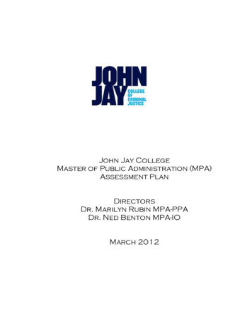
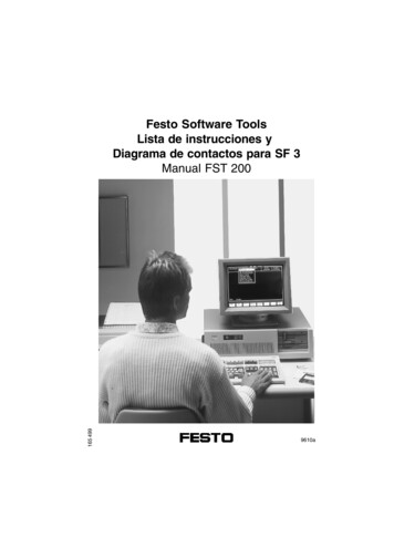
2Overview2.3Valve terminal designThe MPA-S valve terminal consists of the following pneumatic and electrical components. The mostimportant components are shown in the following figure ( Fig. 2.5).213aA1234564aJ239Flat plate silencer or exhaust plateBlanking plateValvesPressure sensor plateElectrical supply plateProportional pressure regulatorFig. 2.556aJ31aJ789aJaA798Right end platePneumatic air supply platePressure regulator plateSub-baseMultiple connector plate; AS interface, CPIinterface or port patternMain components of the MPA-S valve terminalFesto – P.BE-MPA-EN – 1309f – English19
2Overview2.4Description of componentsThe MPA-S valve terminal with CPX terminal or CPI module consists of the following pneumatic components:12781234Only for MPA-S with CPX terminal:Only for MPA-S with CPX terminal: LED/LCDproportional-pressure regulator or coverplateRight end platePneumatic air supply plateFig. 2.62056783654Inscription label with supportSub-base with working ports and seriallinking (bus)Electrical air supply plateSeal (optional separating seal for pressurezone separation)Components of the MPA-S valve terminal with CPX terminal or CPI module, 1st levelFesto – P.BE-MPA-EN – 1309f – English
2Overview123145123Exhaust plate (3/5) or flat plate silencerElectronic module with LEDsValve or blanking plateFig. 2.745Vertical pressure shut-off platePressure regulator plateComponents of the MPA-S valve terminal with CPX terminal or CPI module, 2nd levelFesto – P.BE-MPA-EN – 1309f – English21
2OverviewThe MPA-S valve terminal with electric multi-pin or AS interface consists of the following pneumaticcomponents:14123Right end platePneumatic air supply plateInscription label with supportFig. 2.822455432Manifold block with working lines andelectrical interlinking moduleSeal (optionally separating seal for formingpressure zones)Components of the MPA-S valve terminal with electric multi-pin or AS interface, 1st levelFesto – P.BE-MPA-EN – 1309f – English
2Overview1234214512Exhaust plate (3/5) or flat plate silencerValve or blanking platesFig. 2.9345Vertical pressure shut-off platePressure regulator plateElectronic module with LEDsComponents of the MPA-S valve terminal with electric multi-pin or AS interface, 2nd levelFesto – P.BE-MPA-EN – 1309f – English23 pa
Pneumatic components description Valveterminalwith MPA-Spneumatics Type: MPA-FB MPA-CPI MPA-MPM- and MPA-ASI- 534241 1309f [8028624] Valve terminal MPA-S