Transcription
Split-type Air-ConditionerMXZ -2C20 NA2Installation ManualFor I NSTALLE RNotice d’installationDestinée à l’I NSTALLATE URManual de instalació nPara el I NSTALADOR This manual only describes the installation of outdoor unit.W hen installing the indoor unit, refer to the installation manual of indoor unit.Any structural alterations necessary for installation must comply w ith local building code requirements. Cette notice ne décrit que l’installation de l’appareil extérieur.Lors de l’installation de l’appareil intérieur, consultez la notice d’installation de cetappareil.Toute altération structurelle requise pour l’installation doit être conforme aux exigences du code du bâtiment local. E n este manual só lo se describe la instalació n de la unidad exterior.Para instalar la unidad interior, consulte el manual de instalació n de dicha unidad.Cualquier modificaci n estructural necesaria para llevar a cabo la instalaci n deber cumplir las normas de edificaci n locales.BH79A325H02 en.indd1EnglishFrançaisEspañ ol2018/03/0516:50:32
ENGLISHRequired Tools for InstallationPhillips scre driver5/32 in. (4 mm) hexagonalLevelw renchScaleFlare tool for R410AUtility knife or scissorsGauge manifold for R410ATorque w renchVacuum pump for R410AW rench (or spanner)Charge hose for R410APipe cutter w ith reamerCONTENTS1.2.3.4.5.BEFORE INSTALLATION . 1OUTDOOR UNI T I NSTALLATI ON . 3FLARING WORK AND PIPE CONNECTION. 5PURGING PROCEDURES, LEAK TEST, AND TEST RUN . 5PUMPING DOWN . 71. BEFORE INSTALLATION1-1. THE FOLLOW ING SHOULD ALW AYS BE OBSERVED FOR SAFETY Be sure to read “THE FOLLOWING SHOULD ALWAYS BE OBSERVED FOR SAFETY” before installing the air conditioner. Be sure to observe the arnings and cautions specified here as they include important items related to safety. After reading this manual, be sure to keep it together ith the OPERATING INSTRUCTIONS for future reference.WARNING Do not install the unit by yourself (user).Incomplete installation could cause fire or electric shock, injury due to the unitfalling, or leakage of ater. Consult the dealer from hom you purchased theunit or a qualified installer. Follow the instructions detailed in the installation manual.Incomplete installation could cause fire or electric shock, injury due to the unitfalling, or leakage of ater. W hen installing the unit, use appropriate protective equipment and toolsfor safety.Failure to do so could cause injury. Install the unit securely in a place that can bear the w eight of the unit.I f the installation location cannot bear the w eight of the unit, the unit could fallcausing injury. Perform electrical w ork according to the installation manual and be sure to usean exclusive circuit. Do not connect other electrical appliances to the circuit.If the capacity of the po er circuit is insufficient or there is incomplete electricalork, it could result in a fire or an electric shock. Ground the unit correctly.Do not connect the ground w ire to a gas pipe, w ater pipe, lightning rod ortelephone ground. Defective grounding could cause electric shock. Do not damage the w ires.Damaged ires could cause fire. Be sure to shut off the main pow er w hen setting up the indoor P.C. boardor w iring.Failure to do so could cause electric shock. Use the specified ires to securely connect the indoor and outdoor units.Attach the ires firmly to avoid applying stress to the terminal bloc .Improper connection could cause fire. Do not install the unit in a place here flammable gas may lea .If gas leaks and accumulates around the unit, it could cause an explosion. Do not use intermediate connection of the pow er cord or the extensioncord. Do not connect many devices to one AC outlet.It could cause a fire or an electric shock. Use the parts provided or specified parts for the installation or .The use of defective parts could cause an injury or leakage of ater due to afire, an electric shock, the unit falling, etc. W hen plugging the pow er supply plug into the outlet, mak e sure that thereis no dust, block age, or loose parts both in the outlet and on the plug.Verify that the pow er supply plug is completely in the outlet.If there is dust, blockage, or loose parts on the po er supply plug or the outlet, it could cause electric shock or fire. If loose parts are found on the po er supplyplug, replace it.Securely attach the electrical cover to the indoor unit and the servicepanel to the outdoor unit.If the electrical cover of the indoor unit and/or the service panel of the outdoorunit are not attached securely, dust, w ater, etc. could collect in the unit andcould cause a fire or an electric shock.W hen installing, relocating, or servicing the unit, mak e sure that no substanceother than the specified refrigerant (R410A) enters the refrigerant circuit.Any presence of foreign substance such as air can cause abnormal pressurerise and may result in explosion or injury. The use of any refrigerant other thanthat specified for the system ill cause mechanical failure, system malfunction,or unit breakdo n. In the orst case, this could lead to a serious impedimentto securing product safety.Do not discharge the refrigerant into the atmosphere. Check that therefrigerant gas does not leak after installation has been completed. Ifrefrigerant leak s during installation, ventilate the room.If refrigerant comes in contact ith a fire, harmful gas could be generated.If refrigerant gas leaks indoors, and comes into contact ith the flame of a fanheater, space heater, stove, etc., harmful gases ill be generated.Use appropriate tools and piping materials for installation.The pressure of R410A is 1.6 times higher than R22. Not using the appropriate tools and materials, or improper installation could cause the pipes to burstcausing an injury.W hen pumping dow n the refrigerant, stop the compressor before disconnecting the refrigerant pipes.I f the refrigerant pipes are disconnected w hile the compressor is running andthe stop valve is open, air could be dra n in and the pressure in the refrigeration cycle could become abnormally high, causing the pipes to burst.W hen installing the unit, securely connect the refrigerant pipes beforestarting the compressor.I f the compressor is started before the refrigerant pipes are connected and thestop valve is open, air could be dra n in and the pressure in the refrigerationcycle could become abnormally high, causing the pipes to burst.Fasten a flare nut ith a torque rench as specified in this manual.If fastened too tight, a flare nut could break and cause refrigerant leakage.Install the unit according to national w iring regulations.Be sure to install a Ground Fault Interrupt (GFI) circuit break er.Failure to install a Ground Fault Interrupt (GFI) circuit breaker may result inelectric shock or fire.CAUTION Perform the drainage/piping w ork securely according to the installation manual.If there is defect in the drainage/piping ork, ater could drip from the unit,and damage household items. Do not touch the air inlet or the aluminum fins of the outdoor unit.This could cause injury.(Could lead to death or serious injury, etc.)(Could lead to serious injury w hen operated incorrectly.) Do not install the outdoor unit w here small animals may live.I f small animals enter the unit and damage its electrical parts, it could cause amalfunction, smoke emission, or fire. Keep the area around the unit clean.1-2. SPECIFICATIONSModelMXZ-2C20NA2Pow er supplyRated VoltageFrequency208 / 230 V60 HzPipe length and height difference *1, *2, *3, *4, *5, *6, *8Max. pipe length per indoor unit /Max. heightMax. no. of bends per indoor unit /for multi-systemdifferencefor multi system82 ft. (25 m) / 164 ft. (50 m)*1 Never use pipes ith thickness less than specified. The pressure resistanceill be insufficient.*2 Use a copper pipe or a copper-alloy seamless pipe.*3 Be careful not to crush or bend the pipe during pipe bending.*4 Refrigerant pipe bending radius must be 4 in. (100 mm) or more.*5 Insulation material : Heat resisting foam plastic 0.045 specific gravity*6 Be sure to use the insulation of specified thickness. Excessive thickness maycause incorrect installation of the indoor unit and insufficient thickness maycause dew drippage.49 ft. (15 m)25 / 50Refrigerantadjustment A *71.08 oz each 5 ft.(20 g/m)*7 I f pipe length exceeds 131.2 ft. (40 m), additional refrigerant (R410A) chargeis required. (No additional charge is required for pipe length less than 131.2 ft.(40 m).)(pipe length (ft.) - 131.2)Additional refrigerant (ft.) A 5Additional refrigerant (m) A (pipe length (m) - 40)*8 The piping specification table does not provide a minimum line set length.Ho ever, indoor units ith connected piping length less than 10 ft. (3m) couldproduce intermittent noise during normal system operation in very quiet environments. Please be aw are of this important information w hen installing andlocating the indoor unit w ithin the conditioned space.Note:When connecting the MFZ-KJ series indoor unit(s) to this outdoor unit, charge additional refrigerant according to the instructions in the table belo .Pipe length ( L )No. of MFZ-KJ indoor units40 m or lessMore than 40 m1 unit100 g additional (Total 2800 g)100 g {(L -40) m x 20 g/m)}2 units200 g additional (Total 2900 g)200 g {(L -40) m x 20 g/m)}E n-1BH79A325H02 en.indd12018/03/0516:50:32
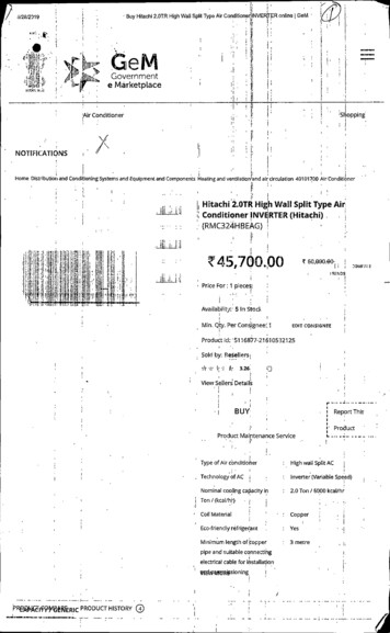
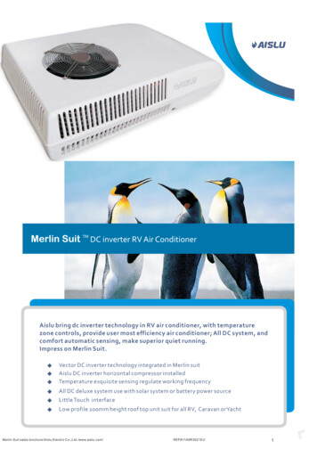
1-3. SELECTING OPTIONAL DIFFERENT-DIAMETER JOINTSI f the diameter of connection pipe does not match the port size of outdoor unit, use optional different-diameter joints according to the follow ing table.(Unit: inch (mm))Optional different-diameter joints (port size of outdoor unit diameter of connection pipe)Port size of outdoor unitMXZ-2C20NA2Liquid / GasA, B UNIT1/4 (6.35) / 3/8 (9.52)3/8 (9.52) 1/2 (12.7) : MAC-A454JP-ERefer to the installation manual of indoor unit for the diameter of connection pipe of indoor unit.1-4. SELECTING THE INSTALLATION LOCATION Where it is not exposed to strong ind. If the outdoor unit is exposed to aw ind during defrosting, the defrosting time w ill be longer. Where airflo is good and dustless. Where rain or direct sunshine can be avoided as much as possible. Where neighbours are not annoyed by operation sound or hot (or cool) air. Where rigid all or support is available to prevent the increase of operationsound or vibration. Where there is no risk of combustible gas leakage. When installing the unit, be sure to secure the unit legs. Where it is at least 10 ft. (3 m) a ay from the antenna of TV set or radio. Operation of the air conditioner may interfere ith radio or TV reception in areashere reception is eak. An amplifier may be required for the affected device. Install the unit horizontally. Please install it in an area not affected by sno fall or blo ing sno . In areasith heavy sno , please install a canopy, a pedestal and/or some baffleboards.Note:It is advisable to make a piping loop near outdoor unit so as to reduce vibrationtransmitted from there.FREE SPACE REQUIRED AROUND OUTDOOR UNIT1. Obstacles above3-15/16 (100)W hen there is no obstacle in front andon the sides of the unit, it is allow edto install the unit w here an obstacle is(500)above the unit only if the space sho n 19-11/16or morein the figure is provided.or moreNote:W hen operating the air conditioner in low outside temperature, be sure tofollow the instructions described below . Never install the outdoor unit in a place here its air inlet/outlet side maybe exposed directly to w ind. To prevent exposure to ind, install the outdoor unit ith its air inlet sidefacing the w all. To prevent exposure to ind, it is recommended to install a baffle board onthe air outlet side of the outdoor unit.Avoid the follo ing places for installation here air conditioner trouble isliable to occur. Where flammable gas could leak. Where there is much machine oil. Salty places such as the seaside. Where sulfide gas is generated such as hot spring, se age, aste ater. Where there is high-frequency or ireless equipment. Where there is emission of high levels of VOCs, including phthalate compounds, formaldehyde, etc., hich may cause chemical cracking.2. Front (blowing) side openAs long as space indicated in thefigure is provided, it is allo ed toinstall the unit w here obstacles arebehind and on the sides of the unit.(No obstacle above the unit)7-7/8 (200) or more13-25/32 (350)or more3-15/16 (100) or more3. Obstacles in front (blowing) onlyWhen there is an obstacle in front of the unit as sho n in the figure, openspace above, behind, and on the sides of the unit is required.4. Obstacles in front and behindThe unit can be used by attaching an optional outdoor blow ing guide(MAC-856SG) (but both sides and top are open).3-15/16 (100) or more19-11/16 (500) or more19-11/16 (500) or moreBlo ing guide (MAC-856SG)5. Obstacles in front, behind and on side(s) When installing the unit in an area that is enclosed ith alls such as averandah, be sure to have enough space as sho n belo .I n this case, the air conditioning capacity and pow er consumption mightdeteriorate. When installing t o or more units, do not install the units in front or behindeach other.6. Service spaceProvide space for service and maintenance as sho n in the figure.Service space7-7/8 (200) or more3-15/16 (100)or more3-15/16 (100) or more19-11/16 (500)or more13-25/32 (350)or more19-11/16 (500)or moreHeight of the obstacle is 47-1/4 (1200) or less19-11/16 (500)or more3-15/16 (100) or more13-25/32 (350) or more13-25/32 (350) or more(Unit: inch (mm))E n-2BH79A325H02 en.indd22018/03/0516:50:32
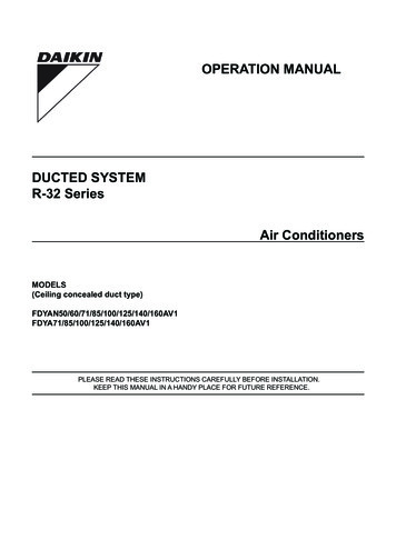
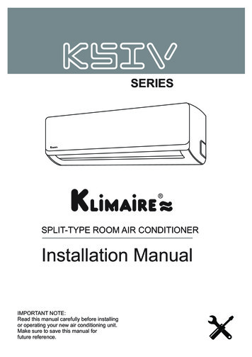
1-5. INSTALLATION DIAGRAMPARTS TO BE PROVIDED AT YOUR SITEAfter the leak test, apply insulating material tightly so that thereis no gap.(A)(B)(C)(D)(E )Pow er supply cord*I ndoor/outdoor unit connecting w ire*E xtension pipeWall hole coverPiping tapeExtension drain hose (or soft PVC(F) hose, 19/32 in. (15 mm) innerdiameter or hard PVC pipe VP16)W hen the piping is to be attached toa w all containing metals (tin plated)or metal netting, use a chemicallytreated w ooden piece 25/32 in. (20mm) or thicker bet een the alland the piping or w rap 7 to 8 turnsof insulation vinyl tape aroundthe piping.To use existing piping, performCOOL operation for 30 minutesand pump do n before removingthe old air conditioner. Remake flareaccording to the dimension for newrefrigerant.Open as a ruleMore than 19-11/16 in.(500 mm) if the frontand both sides are open(G) Refrigeration oil(H)(I )(J)(K)PuttyPipe fixing bandFixing screw for (I )Wall hole sleeveSoft PVC hose, 15 mm inner(L) diameter or hard PVC pipe VP16for drain socket (1)More than 3-15/16 in. (100 mm)More than 7-7/8 in. (200 mm) if there areobstacles to both sides111111Littleamount12 to 72 to 711* Note:Place indoor/outdoor unit connecting ire (B) andpow er supply cord (A) at least 3 ft. (1 m) aw ay fromthe TV antenna ire.More than3-15/16 in.(100 mm)The “Q’ty” for (B) to (K) in the above table is quantityto be used per indoor unit.Units should be installed by licensed contractor according tolocal code requirements.More than 13-25/32 in.(350 mm)Outdoor unit installationOutdoor unit installation840169Air inlet2-3/8 13/16oval holes (Base bolt M8)14-1/415-5/8Air inlet13Air inlet2-U-shape notched holes(Base bolt M8)500Air inletAir outletUnit : inch4-10 21oval holes (Base bolt M8)39617-11/1636137-7/86-1/22-U-shape notched holes(Base bolt M8)330Open as a ruleMore than 19-11/16 in. (500 mm) if theback, both sides and top are openAir outletUnit : mm1-6. DRAIN PIPING FOR OUTDOOR UNITPlease perform the drain piping ork only hen draining from one place.1) Choose one hole to discharge drain and install the drain socket (1) to the hole.2) Close the rest of the holes w ith the drain caps (2).3) Connect the soft PVC hose (L) of 15 mm in the inside diameter on the market ith the drain socket (1) and lead drain.Note:I nstall the unit horizontally.Do not use the drain socket (1) and the drain caps (2) in the cold regions. Drain may freeze and it makes the fan stop.The outdoor unit produces condensate during the heating operation. Select the installation place to ensure to prevent the outdoor unit and/or the grounds from beingw et by drain w ater or damaged by frozen drain w ater.2. OUTDOOR UNIT INSTALLATION2-1. INSTALLING THE UNIT Be sure to fix the unit’s legs ith bolts hen installing it. Be sure to install the unit firmly to ensure that it does not fall by an earthquake or a gust. Refer to the figure in the belo for concrete foundation.Fix here w ithM8 bolts.Make the foundationdeeper.Make the foundationw ider.E n-3BH79A325H02 en.indd32018/03/0516:50:33
2-2. CONNECTING W IRES FOR OUTDOOR UNIT Be sure to use special circuits for room air conditioner.Wiring ork should be based on applicable technical standards.Wiring connections should be made follo ing the diagram.Scre s should be tightened so they on’t loosen.1) Remove the service panel.2) Remove the conduit plate.3) Attach the conduit connector to conduit plate ith lock nut then secureit to the unit ith scre s. Be sure to attach the conduit connectors inthe correct locations according to their sizes.4) Connect ground ires to the TB bed.5) Loosen terminal screw , and connect indoor/outdoor unit connectingire (B) from the indoor unit correctly on the terminal block. Be carefulnot to make mis- iring. Fix the ire to the terminal block securely sothat no part of its core is appeared, and no external force is conveyedto the connecting section of the terminal block.6) Firmly tighten the terminal scre s to prevent them from loosening. Aftertightening, pull the ires lightly to confirm that they do not move.7) Perform 5) and 6) for each indoor unit.8) Connect pow er supply cord (A).9) Close the service panel securely. Make sure that 3-2. PIPE CONNECTI ON is completed.OUTDOOR UNI TPow er supply(V, PHASE, Hz)Max. Fuse size(time delay) (A)Min. CircuitAmpacity (A)Fan motor(F.L.A)(R.L.A)Compressor (L.R.A)Control voltageE LE CTRI CAL SPE CI FI CATI ONSMXZ-2C20NA2208/230, 1, 602017.21.7710.715.5I ndoor unit-Remote controller : (W ireless)Indoor unit-Outdoor unit : DC 12-24 VConduit connector(a) Pow er supply(b) I ndoor/outdoorTrade size of conduit3/4 in.1/2 in.Note: Removing the handle increases the effectiveness of the Be sure to reinstall the handle.iring operation.ScrewScrew sConduit connectorLock nutConduit plateService panelRemark :* Use a ring tongue terminal in order to connect a ground w ire to terminal.I NDOOR UNI TTerminal blockTerminal block1-3/8 in.(35 mm) Connect ires to the matching numbers of terminals. Be sure to attach each scre to its correspondent terminalsecuring the cord and/or the w ire to the terminal block .5/8 in.(15 mm)Groundingterminal *20 8 /230 V AC1 phase 60 HzLead w irePow er supply208/230 V AC1 phase 2 ires 60 HzGroundingterminal *Disconnectsw itchGroundingterminal *Terminal blockTerminal blockOUTDOOR UNI TTerminal blockGroundhenCONNECTING W IRES AND CONNECTING GROUND W IRE Use solid conductor Min. AWG14 or stranded conductor Min. AWG14. Use double insulated copper ire ith 600 V insulation. Use copper conductors only.* Follow local electrical code.POW ER SUPPLY CABLE Use solid or stranded conductor Min. AWG8. Use copper conductors only.* Follow local electrical code.GROUND W IRE Use solid or stranded conductor Min. AWG8. Use copper conductors only.* Follow local electrical code.W ARNING: Use the indoor/outdoor unit connecting ire that meets the Standards to connect the indoor and outdoor units and fix the ire tothe terminal block securely so that no external force is conveyedto the connecting section of the terminal block . An incompleteconnection or fixing of the ire could result in a fire.For future servicing, give extra length to the connectingires. Turn on the main po er hen the ambient temperature is -4 F(-20 C) or higher. Under conditions of -4 F (-20 C), it needs at least 4hr stand bybefore the units operate in order to w arm the electrical parts.E n-4BH79A325H02 en.indd42018/03/0516:50:33
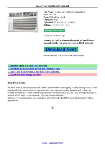
3. FLARING W ORK AND PIPE CONNECTION3-1. FLARING W ORK1) Cut the copper pipe correctly w ith pipe cutter. (Fig. 1, 2)2) Completely remove all burrs from the cut cross section ofpipe. (Fig. 3) Aim the copper pipe do n ard hile removing burrs toprevent burrs from dropping in the pipe.3) Remove flare nuts attached to indoor and outdoor units,then put them on pipe having completed burr removal.(Not possible to put them on after flaring ork.)4) Flaring ork (Fig. 4, 5). Firmly hold copper pipe in thedimension show n in the table. Select A inch (mm) fromthe table according to the tool selected.5) Check Compare the flared ork ith Fig. 6. If flare is noted to be defective, cut off the flared sectionand do flaring ork again.No goodGoodCopperpipeBurr1/4 (ø6.35)3/8 (ø9.52)1/2 (ø12.7)5/8 (ø15.88)B[inch (mm)] Clutch type tool for R410A21/32 (17)7/8 (22)0 to 0.02(0 to 0.5)1-1/32 (26)Pipe cutterTilted Uneven BurredFig. 1Fig. 2Fig. 3Flaring toolI nside is shining w ithout anyscratches.Smooth allaroundCopper pipeDieFlare nutClutch typeEven lengthall aroundW ing nut typeBFig. 4Pipe diameter[inch (mm)]Copper pipeSpare reamerA [inch (mm)]Clutch type tool for R22W ing nut type tool for R22ft-I b10 to 1325 to 3036 to 4254 to 580.06 to 0.08(1.5 to 2.0)0.04 to 0.06(1.0 to 1.5)0.08 to 1.0(2.0 to 2.5)1-5/32 (29)Fig. 5Fig. 6Tightening torqueN m13.7 to 17.734.3 to 41.249.0 to 56.473.5 to 78.4kgf cm140 to 180350 to 420500 to 575750 to 8003-2. PIPE CONNECTION1) Apply a thin coat of refrigeration oil (G) to the flared ends of the pipes and thepipe connections of the outdoor unit.2) Align the center of the pipe w ith that of the pipe connections of the outdoor unit,then hand tighten the flare nut 3 to 4 turns.3) Tighten the flare nut ith a torque rench as specified in the table. Over-tightening may cause damage to the flare nut, resulting in refrigerantleakage. Be sure to rap insulation around the piping. Direct contact ith the bare pipingmay result in burns or frostbite.WARNINGW hen installing the unit, securelyconnect the refrigerant pipes beforestarting the compressor.3-3. INSULATION AND TAPING1) Cover piping joints ith pipe cover.2) For outdoor unit side, surely insulate every piping including valves.3) Using piping tape (E ), apply taping starting from the entry of outdoor unit. Stop the end of piping tape (E) ith tape ( ith adhesive agent attached). When piping have to be arranged through above ceiling, closet or here thetemperature and humidity are high, w ind additional commercially sold insulationto prevent condensation.4. PURGING PROCEDURES, LEA4-1. PURGING PROCEDURES AND LEACAUTIONW hen there are the ports w hich arenot used, mak e sure their nuts aretightened securely.TEST, AND TEST RUNTEST1) Remove service port cap of stop valve on the side of the outdoor unit gas pipe.(The stop valves are fully closed and covered in caps in their initial state.)2) Connect gauge manifold valve and vacuum pump to service port of stop valveon the side of the outdoor unit gas pipe.3) Run the vacuum pump. (Vacuumize for more than 15 minutes.)4) Check the vacuum ith gauge manifold valve, then close gauge manifoldvalve, and stop the vacuum pump.5) Leave as it is for one or t o minutes. Make sure the pointer of gauge manifoldvalve remains in the same position. Confirm that pressure gauge sho s -14.7psi [Gauge] (-0.101 MPa).6) Remove gauge manifold valve quickly from service port of stop valve.7) Fully open all stop valves on the gas pipe and the liquid pipe. Operating ithoutfully opening low ers the performance and this causes trouble.8) Refer to 1-2., and charge the prescribed amount of refrigerant if needed. Besure to charge slow ly w ith liquid refrigerant. Otherw ise, composition of therefrigerant in the system may be changed and affect performance of the airconditioner.9) Tighten cap of service port to obtain the initial status.10) Leak testStop valve cap(Torque 19.6 to29.4 N m, 200to 300 kgf cm)*4 to 5 turns*Close*OpenGauge manifoldvalve (for R410A)HexagonalHandleLowrenchService port cap(Torque 13.7 to17.7 N m, 140 to180 kgf cm)Stop valvefor GASPrecautions w hen using the control valveAControlvalve–0.101MPa Compound pressure( 760 mmHg) gauge (for R410A)Pressure gauge(for R410A)CloseOpenBodyService portStop valvefor LIQUIDHandle HighCharge hose(for R410A)Vacuum pump(for R410A)When attaching the control valveto the service port, valve core maydeform or loosen if excess pressure is applied. This may causegas leak.When attaching the control valve tothe service port, make sure that theCharge hose valve core is in closed position, andthen tighten part A. Do not tighten(for R410A)part A or turn the body hen valvecore is in open position.E n-5BH79A325H02 en.indd52018/03/0516:50:33
4-2. GAS CHARGEModelMXZ-2C20NA2Perform gas charge to unit.1) Connect gas cylinder to the service port of stop valve.2) Perform air purge of the pipe (or hose) coming from refrigerant gas cylinder.3) Replenish specified amount of the refrigerant, hile operating the air conditioner for cooling.Note:In case of adding refrigerant, complyI ndoor unitA–BStop valveLiquidpipeUnionith the quantity specified for the refrigerating cycle.CAUTION:W hen charging the refrigerant system w ith additional refrigerant, be sure to use liquid refrigerant.Adding gas refrigerant may change the composition of the refrigerant in the system and affectnormal operation of the air conditioner. Also, charge the liquid refrigerant slow ly, otherw ise thecompressor ill be locked.To maintain the high pressure of the gas cylinder, w arm the gas cylinder w ith w arm w ater (under104 F (40 C)) during cold season. But never use naked fire or steam.UnionI ndoorunitUnionOutdoorunitStop valve ithservice portUnionRefrigerant gascylinderoperating valve(for R410A)GaspipeGauge manifoldvalve (for R410A)Charge hose(for R410A)Refrigerant gas cylinder for R410A w ith siphonRefrigerant (liquid)E lectronic scale for refrigerant charging4-3. REMOVING THE MAINTENANCE PANELThe setting of Dip Sw itch on the outdoor controller board can be changedithout removing the front panel.Follo the procedures belo to remove the maintenance panel and setthe Dip Sw itch.1) Remove scre (s) hich fix the maintenance panel.2) Remove the maintenance panel, and perform necessary settings.3) I nstall the maintenance panel.Note:Make sure to fix the maintenance panel securely. Incomplete installationcould cause malfunction.Maintenance panel4-4. LOC ING THE OPERATION MODE OF THE AIR CONDITIONER (COOL, DR , HEAT) Description of the function:With this function, once the operation mode is locked to either COOL/DRY modeor HEAT mode, the air conditioner operates in that mode only.* Changing the setting is required to activate this function. Please explain aboutthis function to your customers and ask them hether they ant to use it.[How to lock the operation mode]1) Be sure to turn off the main po er for the air conditioner before making thesetting.2) Set the “3” of SW1 on the outdoor controller board to ON to enable this function.3) To lock the operation mode in COOL/DRY mode, set the “4” of SW1 on theoutdoor controller board to OFF. To lock the operation in HEAT mode, set thesame sw itch to ON.4) Turn on the main pow er for the air conditioner.L E DSW1SW8 7 1SW2SW1ONSW1ON1 2 3 4 5 61 2 3 4 5 6COOL/DRYHEAT4-5. LO ERING THE OPERATION NOISE OF THE OUTDOOR UNIT Description of the function:With this function, the operating noise of the outdoor unit can be lo ered by reducing the operation load, for example, during nighttime in COOL mode. Ho ever,please note that the cooling and heating capacity may lo er if this function is activated.* Changing the setting is required to activate this function. Please explain about this function to your customers and ask them hether they ant to use it.[How to low er the operating noise]1) Be sure to turn off the main po er for the air conditioner before making the setting.2) Set the “5” of SW1 on the outdoor controller board to ON to enable this function.3) Turn on the main pow er for the air conditioner.Low er the operating noiseE n-6BH79A325H02 en.indd62018/03/0516:50:34
4-6. TEST RUN Test runs of the indoor units should be performed individually. See the installation manual coming ith the indoor unit, and make sure all the units operate properly. If the test run ith all the units is performed at once, possible erroneous connections of the refrigerant pipes and the indoor/outdoor unit connecting ires cannot bedetected. Thus, be sure to perform the test run one by one.About the restart protective mechanismOnce the compressor stops, the restart preventive device operates so the compressorill not operate for 3 minutes to protect the air conditioner.W iring/piping correction functionThis unit has a w iring/piping correction function w hich corrects w iring and piping combination. W hen there is possibility of incorrect w iring and piping combination,and confirming the combination is difficult, use this function to detect and correct the combination by follo ing the procedures belo .Make sure that the follo ing is done. Po er is supplied to the unit. Stop valves are open.Note:During detection, the operation of the indoor unit is controlled by the outdoor unit. During detection, the indoor unit automatically stops operation. This is not a malfunction.ProcedurePress the piping/w iring correction sw itch (SW 871) 1 minute or more after turning on the pow ersupply. Correction completes in 10 to 15 minutes. When the correction is completed, its result is sho nby LE D indication. Details are described in the follow ing table. To cancel this function during its operation, press the piping/ iring correction s itch (SW871)again. When the correction completed ithout error,
Grounding terminal * 2 8 /23 V AC 1 phase 6 Hz Grounding terminal * Terminal block Ground OUTDOOR UN T Po er supply 208/230 V AC 1 phase 2 ires 60 Hz Disconnect s itch Grounding terminal * Terminal block Terminal block Terminal block For future servicing, give extra length to the connecting ires. Conduit connector Trade size of conduit (a) Po .