Transcription
Tranquility 20(TS) SeriesTable of ContentsModels TSD/H/V 006 - 07060Hz - HFC-410AINSTALLATION, OPERATION& MAINTENANCE97B0075N06Revised: June 5, 2020Model Nomenclature - General OverviewGeneral InformationUnit Physical DataHorizontal InstallationField Conversion of Air DischargeHorizontal InstallationVertical InstallationPiping InstallationWater-Loop Heat Pump ApplicationsGround-Loop Heat Pump ApplicationsGround-Water Heat Pump ApplicationsWater Quality StandardsElectrical - Line VoltageElectrical - Power WiringElectrical - Power & Low Voltage WiringElectrical - Low Voltage WiringElectrical - Thermostat WiringTS Blower Performance Data - (ECM Motor) Standard Unit - No ReheatTS Blower Performance Data - Standard Unit No Reheat (PSC Motor)TS Blower Performance Data - Units withClimaDry (PSC Motor)ECM Blower ControlTypical Wiring Diagram - Units with CXM Boardand ECM Fan Motor (Single Phase)Typical Wiring Diagram - Units with CXM Boardand PSC Fan Motor (Single Phase)Typical Wiring Diagram - Units with DXM2 Boardand PSC Fan Motor (Three Phase)Typical Wiring Diagram - Units with CXM Board,ECM Fan Motor, and MPC (DDC) Controls(Single Phase)CXM ControlsDXM2 ControlsSafety Features - CXM and DXM2 ControlsClimaDry Modulating Reheat OptionUnit Starting and Operating ConditionsPiping System Cleaning and FlushingFlushing/Purging Units with ClimaDry Unit and System CheckoutUnit Start-Up ProcedureUnit Operating ConditionsPreventive MaintenanceFunctional TroubleshootingPerformance TroubleshootingStart-Up Log SheetFunctional 3335363738394045474950515253556061626364
CLIMATEMASTER WATER-SOURCE HEAT PUMPSTranquility 20 ( TS) SeriesR ev. : J u n e 5 , 2 0 2 0Table of Contents, Cont’d.Warranty (U.S. & Canada)Warranty (International)Revision History2656668C l i m a t e M a s t e r Wa t e r - S o u r c e H e a t P u m p s
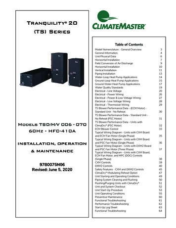
THE SMART SOLUTION FOR ENERGY EFFICIENCYTranquility 20 ( TE) SeriesR ev. : J u n e 5 , 2 0 2 0Model Nomenclature – General Overview1 234 5 6798101112131415TS V 0 2 4 C G C 3 0 C L T SModel TypeTS Tranquility 20Single Stage Scroll(Rotary: Size 006-012)Supply Air & Motor OptionConfigurationV Vertical UpflowH HorizontalD Vertical DownflowUnit Size006 - E,G009 - E,G012 - E,G018 - E,G024 - E,F,G,H030 - E,F,G,H036 - E,F,G,H042 - E,F,G,H,N048 - E,F,G,H,N060 - E,F,G,H,N070 - F,G,H,NRevision LevelControlCXMDXM2CXM w/LONDXM2 w/LONCXM w/MPCDXM2 w/MPCOPTION RANGE1AJK2CLM3ENP4GRSOptionTDBS*V*U*Y*Z*K*N*P*WA Current Revision Sizes 006-012B Current Revision Sizes 018C Current Revision Sizes 024-070AVAILABLEVOLTAGESVoltageG 208/230/60/1E 265/60/1H 208/230/60/3F 460/60/3N 575/60/3w/o DisconnectCDLMNPULTRAQUIETNOYESNOYESStandardS StandardSupply aightTSHPSCTopTSVPSC Hi StaticPSC Hi StaticDownTSDPSC Hi StaticBackTSHPSC Hi ightTSHECM* N/A for Sizes 006-012Return AirL Left ReturnR Right ReturnControlsw/ DisconnectABEKRSHeat Exchanger OptionsTin Plated Air Coil /Microchannel Air Coil*Cupro-Nickel Copper Cupro-NickelNAJPDFNon Coated Air CoilStandardClimaDry ReheatMotorized ValveCabinet1” FILTER 2” FILTER 1” FILTER 2” SNOYESNONOYESYESNONOCopperCETSUWClimaDry reheat coil not coated*Microchannel On Sizes 024-048ClimaDry units are equiped with DMX2Water Circuit Options0 None2 HWG (Coil Only)5 Secondary Circulating Pump6 HWG (Coil Only) w/Auto Flow Regulator 2.5 GPM/Ton7 HWG (Coil Only) w/Auto Flow Regulator 3.0 GPM/Ton8 Auto Flow Regulator 2.5 GPM/Ton9 Auto Flow Regulator 3.0 GPM/TonNote: Above model nomenclature is a general reference. Consult individual engineering guides for detailed information.ClimaDry II Option Notes:1. Unit must have DXM2 control option. 460 volt unit units require a four wire power supply with neutral.2. ClimaDry II may not be combined with motorized water valve, internal secondary circulating pump, or automaticflow regulator options.3. Unit minimum entering air temperature while in the dehumidification, cooling, or continuous fan modes is65ºF DB/55ºF WB. Operation below this minimum may result in nuisance faults.4. A thermostat with dehumidification mode or thermostat and separate humidistat/dehumidistat is required foractivation and control of ClimaDry II.5. Downflow and 575 volt units are not eligible for ClimaDry II.climatemaster.com3
CLIMATEMASTER WATER-SOURCE HEAT PUMPSTranquility 20 ( TS) SeriesR ev. : J u n e 5 , 2 0 2 0General InformationSafetyWarnings, cautions, and notices appear throughout thismanual. Read these items carefully before attempting anyinstallation, service, or troubleshooting of the equipment.DANGER: Indicates an immediate hazardous situation,which if not avoided will result in death or serious injury.DANGER labels on unit access panels must be observed.WARNING: Indicates a potentially hazardous situation,which if not avoided could result in death or serious injury.CAUTION: Indicates a potentially hazardous situation oran unsafe practice, which if not avoided could result inminor or moderate injury or product or property damage.NOTICE: Notification of installation, operation, ormaintenance information, which is important, but which isnot hazard-related. WARNING! WARNING! The EarthPure Application and Service Manualshould be read and understood before attempting to servicerefrigerant circuits with HFC-410A. WARNING! WARNING! To avoid the release of refrigerant into theatmosphere, the refrigerant circuit of this unit must beserviced only by technicians who meet local, state, andfederal proficiency requirements. CAUTION! CAUTION! To avoid equipment damage, DO NOT usethese units as a source of heating or cooling during theconstruction process. The mechanical components and filterscan quickly become clogged with construction dirt and debris,which may cause system damage and void product warranty. WARNING! WARNING! The installation of water-source heat pumps andall associated components, parts, and accessories whichmake up the installation shall be in accordance with theregulations of ALL authorities having jurisdiction and MUSTconform to all applicable codes. It is the responsibility ofthe installing contractor to determine and comply with ALLapplicable codes and regulations.4 WARNING! WARNING! All refrigerant discharged from this unit mustbe recovered WITHOUT EXCEPTION. Technicians mustfollow industry accepted guidelines and all local, state, andfederal statutes for the recovery and disposal of refrigerants.If a compressor is removed from this unit, refrigerant circuitoil will remain in the compressor. To avoid leakage ofcompressor oil, refrigerant lines of the compressor must besealed after it is removed.Inspection - Upon receipt of the equipment, carefullycheck the shipment against the bill of lading. Make sureall units have been received. Inspect the packaging ofeach unit, and inspect each unit for damage. Ensure thatthe carrier makes proper notation of any shortages ordamage on all copies of the freight bill and completes acommon carrier inspection report. Concealed damagenot discovered during unloading must be reported to thecarrier within 15 days of receipt of shipment. If not filedwithin 15 days, the freight company can deny the claimwithout recourse.Note: It is the responsibility of the purchaser to file allnecessary claims with the carrier. Notify your equipmentsupplier of all damage within fifteen (15) days ofshipment.Storage - Equipment should be stored in its originalpackaging in a clean, dry area. Store units in an uprightposition at all times. Stack units a maximum of 3 unitshigh.Unit Protection - Cover units on the job site witheither the original packaging or an equivalent protectivecovering. Cap the open ends of pipes stored on thejob site. In areas where painting, plastering, and/orspraying has not been completed, all due precautionsmust be taken to avoid physical damage to the units andcontamination by foreign material. Physical damage andcontamination may prevent proper start-up and mayresult in costly equipment clean-up.Examine all pipes, fittings, and valves before installingany of the system components. Remove any dirt or debrisfound in or on these components.C l i m a t e M a s t e r Wa t e r - S o u r c e H e a t P u m p s
THE SMART SOLUTION FOR ENERGY EFFICIENCYTranquility 20 ( TE) SeriesR ev. : J u n e 5 , 2 0 2 0General Information, Cont’d.Pre-Installation - Installation, Operation, andMaintenance instructions are provided with eachunit. Horizontal equipment is designed for installationabove false ceiling or in a ceiling plenum. Other unitconfigurations are typically installed in a mechanical room.The installation site chosen should include adequateservice clearance around the unit. Before unit start-up,read all manuals and become familiar with the unit and itsoperation. Thoroughly check the system before operation. CAUTION! CAUTION! All three phase scroll compressors must havedirection of rotation verified at start-up. Verification isachieved by checking compressor Amp draw. Amp drawwill be substantially lower compared to nameplate values.Additionally, reverse rotation results in an elevated soundlevel compared to correct rotation. Reverse rotation will resultin compressor internal overload trip within several minutes.Verify compressor type before proceeding. CAUTION! Prepare units for installation as follows:1. Compare the electrical data on the unit nameplate withordering and shipping information to verify that thecorrect unit has been shipped.2. Keep the cabinet covered with the original packaginguntil installation is complete and all plastering, painting,etc. is finished.3. Verify refrigerant tubing is free of kinks or dents andthat it does not touch other unit components.4. Inspect all electrical connections. Connections must beclean and tight at the terminals.5. Remove any blower support packaging (water-to-airunits only).6. Loosen compressor bolts on units equipped withcompressor spring vibration isolation until thecompressor rides freely on the springs. Removeshipping restraints. (No action is required forcompressors with rubber grommets.)7. Some airflow patterns are field convertible (horizontalunits only). Locate the airflow conversion section ofthis IOM.CAUTION! DO NOT store or install units in corrosiveenvironments or in locations subject to temperature orhumidity extremes (e.g., attics, garages, rooftops, etc.).Corrosive conditions and high temperature or humidity cansignificantly reduce performance, reliability, and service life.Always move and store units in an upright position. Tiltingunits on their sides may cause equipment damage. CAUTION! CAUTION! CUT HAZARD - Failure to follow this caution mayresult in personal injury. Sheet metal parts may have sharpedges or burrs. Use care and wear appropriate protectiveclothing, safety glasses and gloves when handling parts andservicing heat pumps.NOTICE! Failure to remove shipping brackets fromspring-mounted compressors will cause excessivenoise, and could cause component failure due toadded vibration.8. Locate and verify any hot water generator (HWG),hanger, or other accessory kit located in thecompressor section or blower section.climatemaster.com5
CLIMATEMASTER WATER-SOURCE HEAT PUMPSTranquility 20 ( TS) SeriesR ev. : J u n e 5 , 2 0 2 0Unit Physical DataTranquility 20 Single-Stage (TS) Series (60Hz)Model006009Compressor (1 Each)Factory ChargeHFC-410A (oz) [kg]012018024030036Rotary24 [0.68]32 [0.91]042048060070Scroll34 [0.96]50 [1.13]9x7[229 x 178]41 [1.16]41 [1.16]48 [1.36]68 [1.93]68 [1.93]136 [3.86]141 [4.0]11 x 10[279 x 254]11 x 10[279 x 254]11 x 10[279 x 254]11 x 10[279 x 254]11 x 10[279 x 254]10 x 10[254 x 254]10 x 10[254 x 254]10 x 10[254 x 254]11 x 10[279 x 254]11 x 10[279 x 1/2”1/2”0.76 [2.88]0.92 [3.48]1.24 [4.69]1.24 [4.69]1.56 [5.91]1.56 [5.91]ECM Fan Motor & BlowerBlower Wheel Size(dia x w) - (in) [mm]N/AN/AN/ABlower Wheel Size(dia x w) - (in) [mm]6X5[152 X 127]6X5[152 X 127]6X5[152 X 127]9x7[229 x 178]FPT (in)1/2”1/2”1/2”3/4”9x7[229 x 178]9x7[229 x 178]PSC Fan Motor & Blower (3 Speeds)9x7[229 x 178]9x7[229 x 178]Water Connection Size3/4”3/4”HWG Connection SizeFPT (in)N/AN/AN/A1/2”1/2”Coax VolumeVolume (US Gallons)[liters]0.17 [0.64]0.29 [1.10]0.45 [1.70]Air Coil Dimensions(h x w) - (in) [mm]16 x 16[406 x 406]UpflowOnly16 x 16[406 x 406]UpflowOnly16 x 16[406 x 406]UpflowOnly24 x 20[610 x 508]28 x 20[711 x 508]28 x 20[711 x 508]28 x 25[711 x 635]32 x 25[813 x 635]32 x 25[813 x 635]36 x 25[914 x 635]36 x 25[914 x 635]Standard Filter - 1”[25.4mm]Throwaway,qty (in) [mm]16 x 20[406 x 508]16 x 20[406 x 508]16 x 20[406 x 508]24 x 24[610 x 610]28 x 24[711 x 610]28 x 24[711 x 610]28 x 30[711 x 762]2 - 16 x 30[2 - 406 x 762]2 - 16 x 30[2 - 406 x 762]1 - 16 x 30;1 - 20 x 30[1 - 406 x 762;1 - 508 x 762]1 - 16 x 30;1 - 20 x 30[1 - 406 x 762;1 - 508 x 762]Weight - Operating,(lbs) [kg]136 [62]156 [71]160 [73]257 [117]266 [121]268 [122]327 [148]414 [188]416 [189]441 [200]443 [201]Weight - Packaged,(lbs) [kg]146 [66]166 [75]170 [77]267 [121]276 [125]278 [126]337 [153]424 [192]426 [193]451 [205]453 [205]Air Coil Dimensions(h x w) - (in) [mm]16 x 16[406 x 406]16 x 16[406 x 406]16 x 16[406 x 406]18 x 27[457 x 686]18 x 31[457 x 787]18 x 31[457 x 787]20 x 35[508 x 889]20 x 40[508 x 1016]20 x 40[508 x 1016]20 x 45[508 x 1143]20 x 45[508 x 1143]Standard Filter - 1”[25.4mm]Throwaway,qty (in) [mm]16 x 20[406 x 508]16 x 20[406 x 508]16 x 20[406 x 508]2 - 18 x 18[2 - 457 x457]2 - 18 x 18[2 - 457 x457]2 - 18 x 18[2 - 457 x 457]1 - 12 x 20;1- 20 x 25[1 - 305 x 508;1 - 508 x 635]1 - 18 x 20;1 - 20 x 24[1 - 457 x 508;1 - 508 x 610]1 - 18 x 20;1 - 20 x 24[1 - 457 x 508;1 - 508 x 610]2 - 20 x 24[2 - 508 x 610]2 - 20 x 24[2 - 508 x 610]Weight - Operating,(lbs) [kg]136 [62
Typical Wiring Diagram - Units with CXM Board, ECM Fan Motor, and MPC (DDC) Controls (Single Phase) 38 CXM Controls 39 DXM2 Controls 40 Safety Features - CXM and DXM2 Controls 45 ClimaDry Modulating Reheat Option 47 Unit Starting and Operating Conditions 49 Piping System Cleaning and Flushing 50 Flushing/Purging Units with ClimaDry 51 Unit and System Checkout 52