Transcription
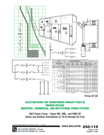
Price 7.50SELECTION GUIDE FOR TRANSFORMER-PRIMARY FUSES INMEDIUM-VOLTAGEINDUSTRIAL, COMMERCIAL, AND INSTITUTIONAL POWER SYSTEMSS&C Power Fuses – Types SM, SML, and SMD-20Indoor and Outdoor Distribution (4.16 kv through 34.5 kv)Supersedes Data Bulletin 240-110 dated 4-12-82 1984S&C ELECTRIC COMPANY ChicagoS&C ELECTRIC CANADA LTD. RexdaleDATA BULLETIN240-110Page 1 of 78August 6, 1984
-Types SM, SML, and SMD-20Indoor and Outdoor Distribution (4.16 kv through 34.5 kv)S8C Power FusesI TABLE OF CONTENTSISectionPage NumberGENERAL . . . . . . . . . . . .2Select the Primary Fuse Rating . . . . . . . . . . . . . . . . . . . . . . . . . . . . . . . . . . . . . . . . . . .5Accommodate Expected Loading Levels. . . . . . . . . . . . . . . . . . . . . . . . . . . . . . . . . . .6APPLICATION PRINCIPLESWithstand Inrush Currents . . . . . . . . . . . . . . . . . . . . . . . . .Protect Transformer Against Damaging Overcurrents. . .Coordinate with Other Protective Devices . . . . . . . . . . . . 16Protect Downstream Conductors Against Damaging Overcurrents . . . . . . . . 27THE FUSE SELECTION TABLESIntroduction to Fuse Selection Tables . . . . . . . . . . . . . . . . . . . . . . . . . . . . . . . . . . . .29Basis for Listings in the Fuse Selection Tables . . . . . . . . . . . . . . . . . . . . . . . . . . .31Examples. . . . . . . . . . . . . . . . . . . . . . . . . . . . . . . . . . . . . . . . . . . . . . . . . . . . . . . . . . . . . .37Fuse Selection Tables . . . . . . . . . . . . . . . . . . . . . . . . . . . . . . . . . . . . . . . . .How to Use the Fuse Selection Tables . . . . . . . . . . . . . . . . . . . . . . . . . .I GENERALThis d a t a bulletin is a guide for the selection, application, a n d coordination of S&C Power Fuses-Types SM,SML, a n d SMD-20 when applied on the primary side ofmedium-voltage transformers in industrial, commercial, a n d institutional power systems. The informationa n d recommendations presented i n this publicationapply regardless of whether the fuses are connecteddirectly to the transformer primary or are remotely connected through insulated cable or enclosed bus duct. Forthe purpose of this guide, medium-voltage transformersare those having primary voltage ratings between 4.16kv a n d 34.5 kv, with either low-voltage (208 v, 240 v,480 v, or 600 v) or medium-voltage (2.4 kv or 4.16 kv)secondaries.The function of a transformer primary-sideprotectivedevice is, in general, to provide system protection a s1well a s transformer protection. With respect to systemprotection, a primary-side protective device shoulddetect a potentially damaging overcurrent conditiona n d operate promptly to isolate only the faulted segment, thereby minimizing the short-circuit stresses onthe remainder of the system a n d limiting the extent ofthe service interruption to only the affected segment.For transformer protection, a primary-side protectivedevice should operate promptly in response to a bus orcable fault located between the transformer a n d thenearest secondary-side overcurrent protective device. I tshould further provide backup protection for the transformer in the event the secondary-side overcurrent protective device either fails to operate due to a malfunction, or operates too slowly due to incorrect (higher)ratings or settings. To best achieve these objectives,group protection of transformers is not generally recom-2404 10 DATA BULLETINPage 2 of 78August 6,1984AS&C ELECTRIC COMPANY. C h i c a g oS&C ELECTRIC CANAOA LTO - Rexdale
ISelection Guide for Transformer-Primary Fuses in Medium-VoltageIndustrial, Commercial, and Institutional Power SystemsIGENERALmended-each transformer should be individually protected. The ampere rating of a primary-side protectivedevice selected to accommodate the total loadingrequirements of two or more transformers would typically be so large t h a t only a small degree of secondaryfault protection-and almost no backup protectionwould be provided for each individual transformer.Moreover, for group-protection situations involvingtransformers of unequal sizes, t h e ampere rating of theprimary-side protective device might even be greatert h a n the already large maximum ampere rating permitted by the National Electrical Code for the smallesttransformer. In addition, with group protection of transformers, the degree of service continuity is significantlyreduced, since a fault associated with a n y one transformer protected by a given device will result in the lossof service to all transformers protected by t h e device. Avariety of primary-side protective devices such as circuit breakers, solid-material power fuses, and currentlimiting fuses are available to accomplish the abovetasks.In industrial, commercial, a n d institutional powersystems, circuit breakers have been used for applications requiring complex relaying schemes or high continuous currents. However, for most applications achoice of either circuit breakers or power fuses is available. Fuses have achieved widespread use in most suchapplications because of their simplicity, economy, fastresponse characteristics, a n d freedom frommaintenance.Circuit breakers a n d their associated relays are commonly used where the reclosing capability of the circuitbreaker is a n advantage, such as applications involvingoverhead lines which have a relatively high incidence oftransient or temporary faults. This reclosing feature isneither useful nor desirable i n industrial, commercial,a n d institutional power systems where the conductorsa r e arranged i n cable trays or enclosed in conduit or busduct. The incidence of faults on these systems is low,a n d the rare faults t h a t do occur are not transient andresult i n significant damage t h a t would only be exacerbated by a n automatic reclosing operation.The relaying associated with circuit breakers is available i n varying degrees of sophistication and complexity. Systems requiring differential protection, reversepower relaying, or non-current-magnitude tripping ofthe protective device typically require circuit breakers.However, the sizes of transformers normally associatedwith industrial, commercial, a n d institutional powersystems generally do not warrant such sophisticatedprotection. Indeed, many users find t h a t the complexityof such protective relaying, with its requirement forperiodic t e s t i n g a n d r e c a l i b r a t i o n , i s a d i s t i n c tdisadvantage.Circuit breakers are also used in applications requiring a very high-above 720 amperes-continuous current-carrying capability. While this may be a n advantage in some cases, a higher degree of service continuitycan be achieved with less expensive power fuses bysubdividing the system into a larger number of discretesegments, with the result that a fault on one segment oft h e system affects fewer loads. This high‘degree of segmentation also allows the use of smaller transformerslocated strategically throughout the system, eliminating the need for the unnecessarily long, high-ampacitysecondary conductors t h a t are required where fewer,larger, widely separated transformers are used.Where high continuous current-carrying capability isnot required and where reclosing or sophisticated relayi n g is not justified-as is the case in the majority oftransformer protection applications in medium-voltagei n d u s t r i a l , commercial, a n d i n s t i t u t i o n a l powersystems-power fuses offer a number of advantages.Power fuses are simple to install a n d require no maintenance of a n y kind-even after years of inattention,power fuses will operate properly. Recalibration isneither required nor possible. Hence, elaborate testingprocedures a r e not needed, eliminating the possibilityt h a t a carefully engineered coordination plan will accidentally be disturbed. Power fuses, unlike circuit breakers, provide fault protection for the system withoutdependence on a source of control power, such as storage batteries a n d their chargers. Such batteries may befound completely discharged and t h u s incapable oftripping the circuit breaker should a fault occur. I n addition, for high-magnitude faults, power fuses have inherently faster response characteristics t h a n circuit breakers, permitting more rapid removal of faults from thesystem with these advantages:1. The duration of the voltage “dip” associated with thefault is reduced significantly, minimizing the potential for disruption of the remaining loads;2. The duration of stresses on motors i n other segmentsof t h e system is shortened;3 . The conductor temperature rise due to the fault current is lessened, permitting t h e use of conductors oneor more sizes smaller t h a n those required by sloweroperating circuit breakers, resulting in considerablesavings; andDATA BULLETINS&C ELECTRIC COMPANY- ChicagoS & C ELECTRIC CANADA LTO Rexdale2404 10Page 3 of 78August 6,1984
SBC Power Fuses-Types SM, SML, and SMD-POIndoor and Outdoor Distribution (4.16 kv through 34.5 kv)1 GENERAL4. The upstream protective device can be set to operatefaster-for better protection-while still coordinati n g with the transformer-primary fuse.Thermal damage to three-phase motors due to singlephasing-once thought to be a problem associated withthe use of power fuses on the primary side of a transformer-is of no concern, since the National ElectricalCode requires t h a t motors be equipped with a n overcurrent protective device in each of the threesupply phases.In addition, devices are now widely available whichdetect open-phase conditions caused by blown fuses a n dsuch other events as utility-line burndown, broken conductors, single-phase switching, or equipment malfunctions, a n d which initiate a switching operation to isolate the load or transfer to a n alternate source. Furthermore, power fuses provide selective isolation of onlyfaulted phases of three-phase feeders serving singlephase loads, unlike the undiscriminating operation ofcircuit breakers which remove all three phases from thesystem-even on single-phase faults.As mentioned above, there a r e two types of powerfuses: solid-material fuses a n d current-limiting fuses,with significantly different performance characteristics which materially affect their suitability fortransformer protection. S&C Types SM, SML, a n d SMDPower Fuses are of the solid-material type, a n d havefusible elements t h a t a r e nondamageable and nonaging. T h e time-current characteristics of S&C PowerFuses are permanently accurate-neither age a n d vibration, nor surges t h a t heat t h e element nearly to thesevering point will affect the characteristics of thesefuses. There is no need for a n y “safety zones” or “setback allowances.” As a consequence of these performance characteristics, SM, SML, a n d S M D PowerFuses allow fusing closer to the transformer full-loadcurrent, providing the maximum degree of protectionagainst secondary-side faults. I n addition, the ability tofuse closer to the transformer full-load current facilitates coordination with upstream protective devices byallowing the use of lower ampere ratings or settings forthese devices, resulting i n faster response.Current-limiting fuses on t h e other hand, because oftheir construction, are inherently susceptible to elementdamage caused by inrush currents t h a t approach thefuse’s minimum melting time-current characteristiccurve. Because of this potential for damage, a n d becauseof the effects of loading a n d manufacturing toleranceson the time-current characteristic curve, a safety zone orsetback allowance is typically required. This safetyzone or setback allowance, combined with the “shape”of the time-current characteristic curve, results in theselection of a current-limiting fuse ampere rating substantially greater t h a n the transformer full-load current. However, the use of such a high ampere rating isundesirable, since the degree of transformer protectionwill be reduced, a n d coordination with the upstreamprotective device may be jeopardized. Also, since highampere-rated current-limiting fuses typically requiret h e use of two or three lower-ampere-rated fuses connected i n parallel, increased cost and space requirements may be encountered.Selection of the various types of transformer primaryside protective devices a n d their ratings and settingsh a s been a matter of considerable complexity. This publication provides complete, simplified procedures forselecting the optimal transformer-primary fuse, takinginto consideration all of the following factors associatedwith the application:1. System voltage;2. Available fault current;3. Anticipated normal transformer loading schedule,including daily or repetitive peak loads, and emergency peak loads;2404 10 DATA BULLETINPage 4 of 78August 6,1984A-S&C ELECTRIC COMPANY. ChicagoS & C ELECTRIC CANADA LTD Rexdale
ISelection Guide for Transformer-Primary Fuses in Medium-VoltageIndustrial, Commercial, and Institutional Power Systems4. Transformer inrush current, including the combinedeffects of transformer magnetizing-inrush currenta n d the energizing-inrush currents associated withconnected loads-particularly following a momentary loss of source voltage;5 . The degree of protection provided to the transformeragainst damaging overcurrents;6. Coordination with secondary-side as well as otherprimary-side overcurrent protective devices; and7. Protection of the downstream primary-side conductors against damaging overcurrents.These factors are discussed i n detail i n the next section, entitled “Application Principles.” This discussionis followed by tables designed specifically to simplifythe selection of the optimal transformer-primary fusefor your particular applications.The fuse selection tables list fuse ampere ratings a n dspeed characteristics which have been “precoordinated”with the full spectrum of low-voltage and mediumvoltage overcurrent protective devices, such as circuitbreakers, fuses, a n d Class E-2 high-voltage industrialcontrol equipment, thereby eliminating the need to perf o r m graphical coordination studies. The tables featurea specially designed “Transformer Protection Index”which indicates the degree of transformer protectionprovided by the primary fuse, as well as listings of theloading capabilities of the fuses when used with each oft h e transformers shown. You need only refer to thesetables to obtain the information required to make yourselection.APPLICATION PRINCIPLES 1Select the Primary Fuse Rating.A transformer-primary fuse must be selected for thevoltage rating, the available fault current, a n d the continuous current-carrying requirement of the circuit onwhich it is to be applied. Since there are a multitude ofvoltage, short-circuit interrupting, a n d maximum ampere ratings available, you should choose the most economical primary fuse t h a t will meet both your presenta n d your future requirements. In addition, from thewide variety of ampere ratings and speeds available,you should select the primary fuse providing the optimum protection for the transformer against secondaryside faults.V o l t a g e rating. The maximum design voltage ratingof t h e transformer-primary fuse should equal or exceedthe maximum phase-to-phase operating voltage level ofthe system. S&C Types SM, SML, a n d S M D PowerFuses a r e not “voltage critical,” since they do not produce overvoltages, and therefore, they may be applied a ta n y system operating voltage equal to or less t h a n themaximum design voltage rating of the fuse. Currentlimiting fuses, in contrast, inherently develop a n overvoltage during fault-current interruption. This overvoltage typically restricts the application of current-limitingfuses to t h e same system-voltage class as the maximumvoltage rating of the current-limiting fuse, in order toavoid exposing system components such as surge arresters a n d dry-type transformers to damage from excessivevoltages.S h o r t - c i r c u i t i n t e r r u p t i n g rating. The symmetricalshort-circuit interrupting rating of the transformerprimary fuse should equal or exceed the maximumavailable fault current at the fuse location. Whendetermining the interrupting rating of the primary fuse,you should consider the X/R ratio of the system a t thefuse location, since power fuses may have higher-thannominal symmetrical interrupting ratings for thoseapplications where the X/R ratio is less t h a n the valueof 15 specified by ANSI Standards.* You may as a resultbe able to use a less expensive primary fuse having alower nominal symmetrical interrupting rating. Referto the fuse manufacturer’s recommendations for thesehigher symmetrical short-circuit interrupting ratings.The interrupting rating of t h e transformer-primaryfuse should be chosen with sufficient margin to accommodate anticipated increases in the interrupting dutydue to system growth. Again, since fuses are availablewith a wide variety of interrupting ratings, you shouldchoose a primary fuse having a n interrupting ratingonly as large as necessary to meet your present andfuture requirements.A m p e r e rating and speed characteristic. The ampere rating a n d speed characteristic of the transformerprimary fuse should be selected to (1)accommodate theanticipated normal transformer loading schedule,including daily or repetitive peak loads, a n d emergencypeak loads; (2) withstand the magnetizing-inrush current associated with the energizing of a n unloadedtransformer, as well as the combined magnetizing- a n dload-inrush currents associated with the re-energization of a loaded transformer following a momentary*ANSI Standard C37.46, Specifications for Power Fuses and FuseDisconnecting Switches.DATA BULLETINS&C ELECTRIC COMPANY. ChicagoS & C ELECTRIC CANAOA LTD . Rexdale240.1 10Page 5 of 78August 6,1984
Types SM, SML, and SMD-20Indoor and Outdoor Distribution (4.16 kv through 34.5 kv)SBC Power Fuses1APPLICATION PRINCIPLESloss of source voltage; (3) protect the transformer againstdamaging overcurrents; a n d (4) coordinate with secondary-side as well as other primary-side overcurrent protective devices. These principles, which are examined ingreater detail in the following sections, provide thebasic foundation of transformer-primary fuse selection.Accommodate Expected LoadingLevels. . .In general, the transformer-primary fuse should beselected based on the anticipated normal transformerloading schedule, including daily or repetitive peakloads. The primary fuse ultimately selected should havea continuous loading capability, as differentiated fromits ampere rating, equal to or greater t h a n this highestanticipated loading level. Refer to the fuse manufacturer’s recommendations for such loading capabilityvalues. Recommendations for S&C Power Fuses-TypesSM, SML, a n d SMD-80 used for transformer protectionare included i n the fuse selection tables presented in thisguide.Conditions may occur during which the transformerwill be loaded far i n excess of the normal loading schedule. Such emergency peak loading typically occurswhen one of two transformers (in a duplex substation,for example) is compelled, under emergency conditions,to carry the load of both transformers for a short periodof time. Where emergency peak loads are contemplated,the transformer-primary fuse ultimately selected shouldhave a n emergency peak-load capability a t least equalto the magnitude a n d duration of the emergency peakload. I t is important to remember that a transformerprimary fuse should be selected to accommodate-not tointerrupt-emergency peak loads. This requirementmay result i n the selection of a primary fuse ampererating larger t h a n would be required for a similarlyrated single transformer installed alone, a n d therefore7-15.014.013.012.0Load Current, in Percent of Transformer Full-Load CurrentFigure 1. Curve lor determining magnitude of combined magnetizing- and load-inrush current.2404 10 DATA BULLETINPage 6 of 78August 6,1984S&C ELECTRIC COMPANY. C h i c a g oS&C ELECTRIC CANADA LTD Rexdale
ISelection Guide for Transformer-Primary Fuses in Medium-VoltageIndustrial, Commercial, and Institutional Power SystemsAPPLICATION PRINCIPLESthe degree of transformer protection provided by theprimary fuse may be reduced.Withstand inrush Currents.When a n unloaded distribution or power transformer isenergized, there occurs a short-duration inrush of magnetizing current which the transformer-primary fusemust be capable of withstanding without operating (or,in the case of current-limiting fuses, without sustainingdamage to the fusible element). T h e integrated heatingeffect on the primary fuse a s a result of this inrushcurrent is generally considered equivalent to a currenthaving a magnitude of 12 times the primary full-loadcurrent of the transformer for a duration of 0.1 second.The minimum melting time-current characteristic of theprimary fuse should be such that the fuse will not operate (or again, in the case of current-limiting fuses, sustain damage to the fusible element) as a result of thismagnetizing-inrush current.The transformer-primary fuse must also be capable ofwithstanding the inrush current that occurs when atransformer t h a t is carrying load experiences a momentary loss of source voltage, followed by re-energization(such a s occurs when a source-side circuit breaker operates to clear a temporary upstream fault, and thenautomatically recloses). In this case, the inrush currenti s made up of two components: the magnetizing-inrushcurrent of the transformer, and the inrush current associated with the connected loads. The ability of the primary fuse to withstand combined magnetizing- and1load-inrush current is referred to as “hot-load pickup”capability.T h e integrated heating effect on the transformerprimary fuse a s a result of the combined magnetizingand load-inrush current is equivalent to a current having a magnitude of between 12 and 15times the primaryfull-load current of the transformer for a duration of 0.1second. The specific multiple of primary full-load current is a function of the transformer load immediatelypreceding the momentary loss of source voltage, a sillustrated in the curve i n Figure 1. The minimum melting time-current characteristic of the primary fuse(adjusted a s described below) should exceed the magnitude and duration of the combined inrush current.The minimum melting time-current characteristiccurves for medium-voltage power fuses are determinedi n accordance with ANSI Standards,* which specifytesting of fuses at a n ambient temperature of 25”C, andwith no initial load. I n practice, every fuse is carrying aload, which raises the temperature of the fusible element, and hence reduces the melting time for a givenvalue of current. To ensure t h a t the transformer-primaryfuse can withstand hot-load pickup current (and to provide precise coordination between the primary fuse anddownstream overcurrent protective devices), it is necessary to adjust the published minimum melting timecurrent characteristic curve of the primary fuse toreflect the reduced melting time for each specific level offuse loading. Figure 2 illustrates a typical curve used for*ANSI Standard (37.46, Specifications for Power Fuses a n d Fuse[)isconnecting Switches.20406080100120Load Current, in Percent of Transformer-Primary Fuse Ampere Rating----Figure 2. Curve for determining loading adjustment factor.DATA BULLETINS&C ELECTRIC COMPANY. ChicagoS & C ELECTRIC CANADA LTD Rsxdale2404 10Page 7 of 78August 6,1984
SCLC Power Fuses- Types SM, SML, and SMD-20Indoor and Outdoor Distribution (4.16 kv through 34.5 kv)1APPLICATION PRINCIPLESmaking such a n adjustment, a n d Figure 3 illustrates theminimum melting time-current curve of a primary fuseso adjusted.Published total clearing timecurrent curve of transformer-Published minimum meltingtime-current curve oftransformer-primaryfuseSolid-material power fuses h a v e helically coiled,stress-relieved silver fusible elements t h a t are of solderless construction a n d are surrounded by air. Because ofthis construction, t h e adjustment mentioned aboveregarding t h e level of prefault load is t h e only adjustment t h a t need be made to ensure sufficient hot-loadpickup capability a n d precise coordination with downstream protective devices. I n such power fuses, the fusible element is free from mechanical a n d thermal stressa n d confining support, a n d therefore is not subject todamage-even by inrush currents that approach but donot exceed t h e fuse’s minimum melting time-currentcharacteristic curve, adjusted to reflect t h e assumed prefault load. Fuses with other element designs, in contrast,require additional or larger adjustments to their minimum melting time-current characteristic curves to recognize the physical or metallurgical damage to the fusible element that can result from such surge currents.Current-limiting fuses, i n particular, have fusibleelements which consist of a number of very fine diameter silver wires, or one or more perforated or notchedsilver ribbons, surrounded by, a n d in contact with, afiller material such as silica sand. Because of this construction, current-limiting fuses are susceptible to element damage caused by current surges t h a t approachthe fuse’s minimum melting time-current characteristiccurve. This damage may occur i n one or more of thefollowing ways:1. The fusible element may melt but not completelyseparate, because the molten silver is constrained byt h e filler material. The silver then solidifies, but witha different cross-sectional area.2. One or more, but not all, of the parallel silver wires orribbons of the fusible element may melt and separate.Adjusted minimurn meltingtime-current curve oftransformer-primaryfuse ( p u blished fuse minimum meltingtime-current curve adjusted toreflect the assumed prefaultload)Current3. The fusible element may break as a result of fatiguebrought about by localized buckling of the fusibleelement from thermal expansion and contraction.Certain current-limiting fuses utilize a eutectic or “M”spot consisting of a drop of tin or tin alloy deposited onthe silver element. The tin or tin alloy melts and amal-*Figure 3. The total clearing and the minimum melting time-currentcurves of a 100E-ampere translormer-primary fuse, with the minimum melting curve adjusted to reflect the reduced melting timeresulting from an assumed prefault load current of 87.5 amperes.2404 10 DATA BULLETINPage 8 of 78August 6,1984S&C ELECTRIC COMPANY C h i c a g o-S&C ELECTRIC CANADA LTO Rexdale
ISelection Guide for Transformer-Primary Fuses in Medium-VoltageIndustrial, Commercial, and Institutional Power SystemsAPPLICATION PRINCIPLESgamates (combines)with thesilver element at a temperature lower t h a n the melting temperature of the silverelement, thereby initiating fuse operation at lower levels of fault current t h a n for t h e silver element alone.Current-limiting fuses t h a t utilize “M” spots are evenmore susceptible to element damage t h a n other types ofcurrent-limiting fuses, since the “M” spot may only partially melt a n d amalgamate when exposed to currentsurges.Damage to fusible elements of current-limiting fuses,as described above, may shift or alter their time-currentcharacteristics, resulting i n a loss of complete coordination between the fuses a n d other downstream overcurrent protective devices. Moreover, a damaged currentlimiting fuse element m a y melt due to a n otherwiseharmless inrush current, but the fuse m a y fail to clearthe circuit due to insufficient power flow-with the fusecontinuing to arc a n d burn internally due to loadcurrent flow.Because of the potential for damage to the fusibleelement from inrush currents, a n d because of the effectsof loading and manufacturing tolerances, current-limiting fuse manufacturers typically require that, whenapplying such fuses, the minimum melting time-currentcharacteristic curves be adjusted to allow for these variables. These adjustments are referred to as “safetyzones” or “setback allowances,” a n d range from 25?6 i nterms of time to 25‘K in terms of current. The latter canresult in a n adjustment of 250% or more in terms of time,depending on the slope of the time-current characteristic curve a t the point where the safety zone or setbackallowance is measured.The S&C Types SM, SML, a n d SMD-20 Power Fusescovered i n this publication are available in two speedcharacteristics: Standard Speed, TCC No. 153;a n d SlowSpeed, TCC No. 119. The time-current characteristiccurves for these fuses a r e of the inverse-time form withsufficient time delay so t h a t , i n either speed, a fusehaving a n ampere rating even somewhat less t h a n thetransformer full-load current will withstand t h e inrushcurrents described above, for typical industrial transformer loading levels.Current-limiting fuses, i n contrast, have inherentlysteeper (faster) time-current characteristics. As a consequence, manufacturers of current-limiting fuses ordinarily recommend the use of a n ampere rating substantially higher t h a n the transformer full-load current inorder to prevent the fuse from operating or sustainingdamage due to inrush currents. However, the use of ahigher ampere rating is undesirable for three reasons:(1) protection for the transformer may be greatlyreduced; (2) coordination with the upstream protectivedevice may be jeopardized; a n d (3) higher-ampere-ratedcurrent-limiting fuses (usually above 100 amperes) typically require t h e use of two or three lower-ampere-ratedfuses connected in parallel, resulting in significantlyincreased cost a n d space requirements.Protect Transformer AgainstDamaging Overcurrents .,The most important application principle to be considered when selecting a transformer-primary fuse is t h a tit must protect the transformer against damage frommechanical a n d thermal stresses resulting from a secondary-side fault t h a t is not promptly interrupted. Aprope
INDUSTRIAL, COMMERCIAL, AND INSTITUTIONAL POWER SYSTEMS S&C Power Fuses - Types SM, SML, and SMD-20 Indoor and Outdoor Distribution (4.16 kv through 34.5 kv) S8C Power Fuses - Types SM, SML, and SMD-20 . Power fuses, unlike circuit break- ers, provide fault protection for the system without dependence on a source of control power, such as stor-