Transcription
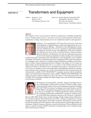
EPRI Underground Distribution Systems Reference BookCHAPTER 16Transformers and EquipmentAuthors: Stephen L. Cress,Kinectrics. Inc.Ali Naderian, Kinectrics, Inc.Reviewers: Gordon Hayslip, Snohomish PUDJohn Igielski, Northeast UtilitiesKen Ochs, We EnergiesJoseph Somma, Consolidated EdisonAbstract:This chapter reviews several aspects related to transformers, including transformerlosses, loading characteristics, selection criteria for pad-mounted transformers,transformer cooling, interpretation of tests on transformers and oil, and capacitors.Stephen L. Cress graduated in 1976 from The University of Torontowith a Bachelor of Applied Science in Electrical Engineering. He is currently Department Manager – Distribution Asset Management at Kinectrics Inc. Stephen has over 33 years’ experience in specialized technicalinvestigations, research, testing, and applications in the power distribution field based on his work at Federal Pioneer, Ontario HydroResearch Division, and Kinectrics Inc. He has conducted major projects for North American distribution utilities dealing with: transformerloading and sizing, transformer losses and efficiency, asset management, asset conditionassessment, life extension, distribution protection, equipment failure analysis (transformers, switchgear, fuses, capacitors), standard testing, distribution modeling, and development of utility-oriented engineering software. Stephen is the holder of a U.S. patent onhigh-voltage current limiting fuses. He is a co-author of the CEATI reference booksApplication Guide for Distribution Fuses and Engineering Guide for Distribution Overcurrent Protection. Stephen’s work in the development of probabilistic methods for calculating transformer loss evaluation, loss-of-life, and loading have been incorporated in thecommercially available CEATI TRANSIZE TM computer program. He has publishedpapers with international organizations such as IEEE, CIRED, and INTER-RAM, andarticles in power industry magazines. He is the Chair of the harmonized CSA andCNC\IEC TC32 Committees dealing with High Voltage Fuses, and a Professional Engineerin the Province of Ontario.Ali Naderian received his B.Sc. and M.Sc. degrees from Sharif University of Technology in 1998 and the University of Tehran in 2000, respectively. During his studies, his part-time employment experience includedISC (1997-1999) for testing of switchgear and circuit breakers, and ITS(1999-2000) for designing and manufacturing of HV power transformers. He was co-designer of a 3*300-kV cascade HV testing transformer.He compared commercially available RTV coatings for outdoor insulators in his PhD thesis during his research at the University of Waterloo,Ontario (2003-2006). He has been a project manager of high-voltage testing at Kinectrics,Inc. (formerly Ontario Hydro Research) since 2007, working on diagnostics of powertransformers, high-voltage cables, and outdoor insulators. He performs on-line and offline PD measurements for HV apparatus. His research interests include high-voltage testtechniques, dielectric frequency response, and partial discharge. He has published severalpapers, is actively involved in IEEE transformer working groups, and is a registered engineer in the Province of Ontario.16-1
Chapter 16:16.1Transformers and EquipmentINTRODUCTIONThis edition of the Bronze Book covers only a subset ofwhat will be a comprehensive look at underground distribution transformers. Included here are sections ontransformer losses, loading characteristics, padmounted transformer selection criteria, interpretationof tests on transformers and oil, as well as a discussionon capacitors.The next edition will also include an overview of transformer types by application, unit components and coreconstruction, installation options, and insulation types.Additional topics will be transformer cooling, testingand monitoring, and typical examples of failure rootcauses.The reader is encouraged to refer to other sources morebroadly covering this topic, including the Electric PowerDistribution Handbook by Tom Short (2004), PowerTransformers, Principles and Applications by John Winders (2002), and the ABB Distribution Transformer Guide(2002).16.2TRANSFORMER LOSSESLosses in distribution transformers are categorized asload and no-load losses. Load losses vary with thesquare of the load on the transformer, whereas no-loadlosses are continuous and constant regardless of load.16.2.1 No-Load LossNo-load losses (or excitation losses, iron losses, or corelosses) are inherent to the excitation of the transformer.No-load losses are associated with the core design. Theyinclude core loss, dielectric loss, and the loss in the windings due to exciting current. For distribution transformers at 27.6 kV and below, the dielectric loss is negligible.The no-load loss in the transformer core is a function ofthe magnitude, frequency, and wavefor m of theimpressed voltage. No-load losses are affected by voltage fluctuations. When an AC voltage is applied to theterminals of the transformer, magnetizing current flowsthrough the winding, and a magnetic flux appears in thecore. The predominant component is core loss, which iscomposed of hysteresis and eddy current losses.The hysteresis loss is proportional to the frequency anddependent on the area of the hysteresis loop in the B-Hdiagram, and, therefore, characteristic of the materialand a function of the peak flux density.The variable magnetic flux induces current running inpaths perpendicular to the direction of the flux. The16-2EPRI Underground Distribution Systems Reference Bookinduced current, called eddy current, produces losses inthe core plates. The eddy current loss can be calculatedby Equation 16.2-1Peddy π26σ f 2 d 2 B 2V16.2-1Where:σis the core conductivity.ƒis frequency.dis the core thickness.Bis the peak value of the flux density.Vis the core volume.As per Equation 16.2-1, eddy current is controlled byusing laminated core to cut large current loops at thecross section of the core. The no-load loss is the sum ofhysteresis and eddy current losses, as shown in Equation16.2-2.P0 Peddy Ph16.2-216.2.2 Load LossesLoad losses (or copper losses or resistive losses) are primarily a function of the winding design of the transformer. They result from the load current flowing in theprimary and secondary windings.Components of load loss are I2R and stray losses. For adistribution transformer, I2R is in the range of 92-99%of the load loss. The proportion is lower for larger kVAsizes. Load loss is affected by: number of turns of windingmean length of the primary and secondary turnsconductor cross sectionmaterial of the conductor—i.e., copper or aluminumStray losses vary inversely as the temperature, therebymaking necessary the calculation of load loss at a specific temperature such as 85 C. Stray losses have threecomponents: conductor eddy currents, conductor circulating currents, and stray currents in the core wall andcore clamps.The current, which is applied to the windings, createslosses due to the winding resistance. The losses of atransformer are losses incident to a specified load carried by the transformer. Load losses in distribution-classtransformers mainly include I 2 R loss in the windingsdue to load current.Load loss follows Ohm’s law and can be decreased byreducing the number of winding turns, by increasing thecross-sectional area of the turn conductor, or by a com-
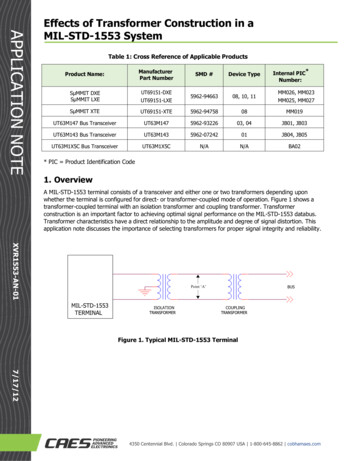
EPRI Underground Distribution Systems Reference Bookbination of both. However, reducing the number ofturns requires an increase of the flux—i.e., an increasein the core cross-section, which increases the iron weightand iron loss. Therefore, a tradeoff has to be madebetween the load loss and the no-load loss.Chapter 16:Transformers and EquipmentTransformer efficiency (η) is the ratio of a transformer’suseful power output to its total power input as indicatedin Equation 16.2-3 (IEEE 2006).Pout Pin Ploss PinPinη 16.2-316.2.3 Total LossThe following summarizing relationships are usefulwhen considering the losses in distribution transformers:No Load Loss α Flux Density α 1/# Turns α 1/ CoreCross SectionLoad Loss α # TurnsWhere:ηis the efficiency.Pin is the input power.Pout is the output power.Ploss is the total power loss of the transformer tobe introduced.Impedance α Reactance α (# Turns)2Initial Cost α Core Material α Winding MaterialTable 16.2-1 summarizes the components of load andno-load losses.In many jurisdictions, government energy agencies havemandated minimum efficiency levels for liquid-filled anddry-type distribution transformers (DOE 2007; NEMA2002). Table 16.2-3 provides an example of the acceptedefficiency levels for liquid-immersed distribution trans-Figure 16.2-1 and Table 16.2-2 provide some typicalload and no-load loss values for distribution transformers. Figure 16.2-1 illustrates how load losses vary withload on the transformer.16.2.4 Transformer EfficiencyTransformer efficiency is related to the amount of wattslosses that occur when the transformer is in operation.Table 16.2-1 Components of Transformer Load and NoLoad LossTypeNo-Load LossaLoad LossaI2R from No-load II2R from load II2R from I supplying LossesMagneticCore Hysteresis LossCore Eddy Current LossStray Eddy Current Loss inInternal componentsConductor EddyCurrent fromLeakage fieldsDielectricDielectric LossElectrica. Where I represents current, and I2R is the currentsquared times the conductor resistance.Figure 16.2-1 Typical load and no-load losses ofdistribution transformers.Table 16.2-2 Typical Losses for Power Distribution TransformersNo-Load LossWattsEfficiencyaat 50% loadRatingKVALoad Loss 0050000.9954a. Calculated using Equation 16.2-4.16-3
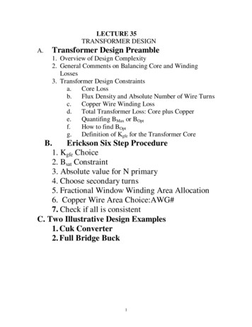
Chapter 16:Transformers and EquipmentEPRI Underground Distribution Systems Reference Bookformers. An example of the minimum efficiency for drytype distribution transformers is shown in Table 16.2-4(DOE 2007). These efficiency values are computed at50% of nameplate-rated load.Efficiency can be expressed directly as a function of theload and no-load losses as in Equation 16.2-4 (NEMA2002). The efficiency values computed using this formula are provided alongside the load and no-load lossesin the examples in Table 16.2-2.η KVA Lp.u.KVA Lp.u. P0 Lp.u.2 PL16.2-4Where:KVA is the transformer rated power.PLis the load loss.P0is the no-load loss.Lp.u. is the per-unit load (the ratio of actual loadto the rated full load).Present distribution transformers are, for the most part,between 98% and 99.5% efficient. For the new transformers, the guideline from (DOE 2007), presented inTables 16.2-3 and 16.2-4, should be followed. Becausevirtually all-electric energy passes through distributiontransformers, losses in these devices, though small, areestimated to constitute as much as 2 to 3% of all energygenerated.Generally transformers are at maximum efficiency whenthey are 50% loaded. When transformers are lightlyloaded, the no-load losses form a large percentage of thepower utilized, and therefore, the efficiency is low. Asthe transformer is loaded to higher levels, the load lossesdominate the efficiency. The maximum efficiency pointis the optimal point of lowest load and no-load losses. Itis determined by the design of the transformer and theoretically could be designed to occur at any load percentage. It typically is designed to occur at 50%, because theaverage load tends to be about 50% of the peak load.However, transformers with high no-load losses areTable 16.2-3 Standard Levels of Efficiency for Liquid-immersed Distribution Transformers (DOE 2007)Table 16.2-4 Standard Levels of Efficiency for Dry-type Distribution Transformers (DOE 2007)16-4
EPRI Underground Distribution Systems Reference Bookmost efficient at 60%-80% load, and transformers withlow no-load losses are most efficient at about 40% load.(See Figure 16.2-2.)16.2.5 Reduction of Transformer LossesReduction of transformer losses and improvement inefficiency can be achieved by reduction of either load orno-load losses. For any given set of core and windingmaterials, reduction of load losses often leads to anincrease in no-load losses and vice versa.Many factors of core design affect no-load losses andcan be altered to reduce these losses. Higher magneticflux density leads to higher losses. Larger gaps in cutcores lead to higher losses. These gaps can be reducedby manufacturing techniques. The thickness of theenamel insulation on the winding conductors affects thesize of the core. High-quality enamel can be used in verythin layers to reduce core size and no-load losses.Mechanical arrangement of the windings and taps alsoaffects the efficient use of space and the size of the core.Traditionally cores have been made from grain-orientedsilicon steel formed into thin sheets and wrapped into arectangular shape. The loss decreases as the thickness ofthe sheets decrease. Standard grades are M-2 at 0.18mm, M-3 at 0.23 mm, M-4 at 0.27 mm, and M-6 at 0.35mm. Losses also depend on the permeability of the steelalloy. Higher permeability leads to lower losses. Thepermeability depends upon the alloy and the orientations of the grains.A large advance in technology occurred in the 1980swith the development of amorphous steel cores. Thesecores are also built up by wrapping thin sheets or ribbons, but the steel itself (such as Co-Fe-Si-B alloy) isquenched during manufacture to ensure that no grainsare formed in the steel. This process increases the effec-Chapter 16:Transformers and Equipmenttive permeability of the steel, thus reducing the losses,but it also decreases the saturation magnetic flux density, which increases the amount of material required inthe core. Together, these effects reduce the no-load lossof the core, but the amorphous steel cores are larger,heavier, and more costly to produce. (Permeabilityincreases by a factor of 4, but saturation flux densitydecreases by a factor of 0.75, requiring 1.3 times asmuch material in the core, so overall loss is lower by afactor of 3.) On average, amorphous core loss values areabout 30% of that for high-efficiency silicon steel, andonly 15% of that for older, less efficient steels.Numerous questions have arisen regarding the mechanical robustness and long-term mechanical performanceof amorphous metals. Short-term testing programs havenot substantiated these beliefs, but the concern persists.More recently nano-crystalline steel has become available for use in transformer cores.The best are based on an Fe-Zr-B alloy that is formed inan amorphous state and then annealed to produce verysmall grain sizes. This approach makes the material lessbrittle and thereby decreases production costs. This steelhas even higher permeability and also higher saturationinduction than the amorphous materials, but it is notyet available in manufactured transformer cores. Thenew steel has 17 times the permeability of steel and 0.89of the saturation flux density; so losses should bereduced by a factor of 15.Load losses are caused primarily by the heating of thewindings by the passage of current (I2R losses). The current is determined by the impedance of the load on thetransformer and the voltage levels and so is not underthe control of the transformer designer. The resistancedepends on the material used in the winding, the crosssectional area of the wires, and the number of turns.Transformer windings are made of either copper or aluminum in round wires, square wires, or flat sheets. Theresistivity of aluminum is about 1.6 times larger thanthat of copper, but aluminum has a lower cost. Manydifferent alloys of aluminum and copper are available.In general, the lower resistance alloys are more expensive and harder to work with in the manufacturing processes, leading to higher initial costs.Figure 16.2-2 Transformer efficiency as a function of load.In addition to choice of material, load losses areaffected by the cross-sectional area of the wire used.Larger wires produce lower load losses, but then thewindings are larger, and this requires a larger core,which increases the no-load losses.16-5
Chapter 16:Transformers and EquipmentEPRI Underground Distribution Systems Reference BookSome load loss is caused by induced currents from adjacent windings. These currents can be reduced by usingcontinuously transposed conductor in the winding andthus reducing load losses. This approach also leads tohigher initial costs.16.2.6 Transformer Short-circuit ImpedanceWhen provided a customer’s cost of no-load and loadlosses, transformer manufacturers will use software thatperforms hundreds of iterations, varying core, winding,and tank options, to arrive at a transformer with anoptimal balance of losses and initial cost.The short-circuit impedance of a transformer is used tocalculate the maximum short-circuit current and isneeded for sizing circuit breakers, fuses, cables, andother equipment connected to the secondary of thetransformer.Transformer impedance (or short-circuit impedance orimpedance voltage) is the percent of per unit voltagethat must be applied to the primary side of a transformer, so that the rated current flows when the secondary terminals are short-circuited. This impedance isformulated as Equation 16.2-5.UZ % Z 100ZP16.2-5As the no-load test result is available, the ohmic part ofthe impedance can be calculated using Equation 16.2-6,and therefore, the inductive part of the impedance canbe derived by Equation 16.2-7.R% P3ϕ load lossMVA3ϕ .106 100X % Z %2 R%216.2-616.2-7In a transformer having a tapped winding, the short-circuit impedance is referred to a particular tap. Unlessotherwise specified, the nominal tap applies and is theimpedance (Z%) that is marked on the nameplate. Theimpedance voltage of distribution transformers withrated power below 630 kVA is usually 4% or less, andthis value is usually around 6% for 630 kVA up to2.5 MVA distribution transformers.For parallel operation of two or more transformers,short-circuit impedance is critical. If paralleled transformers do not have the same short-circuit impedance,the load will be shared in an unbalanced way such thatone transformer can be overloaded and the transformercan be underloaded.16-616.2.7 Cost-of-Losses FormulaThe lifetime cost of a transformer depends on the capital cost of the transformer and the cost of the load andno-load losses during its lifetime. The present valuemethod is often employed to express the lifetime cost interms of a dollar value in the present year. Losses fromdistribution transformers are a significant contributionto distribution system losses, and their reduction represents an opportunity for improving energy efficiencyA cost-of-losses formula for purchasing purposes isoften employed to determine the lifetime costs for various transformer options available to utilities. Comparisons can then be made between more capital intensivelow-loss transformers and less expensive higher-losstransformers.The following paragraphs describe the general formulation of a cost-of-losses formula. Table 16.2-5 defines thequantities used in these equations.Table 16.2-5 Definition of Symbols for Cost of LossesFormulaCAPCapital cost ( )CLLPresent value of cost of load losses ( /W)CLL(m)Cost of load losses for month “m” ( /kW)CLY(y)Cost of load losses for year “y” ( )CNLLPresent value of cost of no-load losses ( /W)CNLL(m)Cost of no-load losses for month “m” ( /kW)DDemand charge, monthly ( /kW)D(m)Demand charge for month “m” ( /kW)EEnergy charge, monthly ( /kWh)EOP(m)Energy charge off-peak for month “m” ( /kWh)EP(m)Energy charge on-peak for month “m” ( /kWh)FYG(y)Factor for yearly load growth accumulated to year“y”g(y)Growth of load for year “y” (%/100)HOP(m)Hours off-peak for month “m” (h)HP(m)Hours on-peak for month “m” (h)i(y)Interest rate for year “y” (%/100)j(y)Inflation rate for year “y” (%/100)PVLCPresent value of lifetime cost ( )LLLoad losses (W)LSFLoss factor (average loss/peak loss)NLLNo-load losses (W)NYNumber of years in economic study periodp(y)Growth of power costs for year “y” (%/100)PVFPresent value factor for a period of yearsPVF(y)Present value factor for year “y”RATLRated load for transformer (kVA)RFResponsibility factor (load at system peak/peakload)2UFUtilization factor (peak load/rated load)
EPRI Underground Distribution Systems Reference BookChapter 16:The basic form of the cost of losses formula, providingthe present value of the lifetime cost (PVLC) of a transformers, is as expressed in Equation 16.2-8.CLL 1 E LSF 12D RF 87601000 100 NYPVLC CAP NLL CNLL LL CLLy 1Common cost-of-losses equations use flat-rate demandand energy charges and fixed annual economic factors,such as interest rate, to evaluate the lifetime costs ofload losses (CLL) and cost of no-load losses (CNLL).The concepts of load factor, loss-factor, utilization factor, and responsibility factor are used to describe theloads on the transformer. A load growth factor can beused to include the influence of rising loads on thetransformer losses over the transformer’s lifetime. Notethat the load growth factor is 1 in the first year, and thenchanges to a fixed factor at the start of the second year.The present value factor includes the influence of economic factors such as inflation of the cost of power andinterest rates. The growth in power costs factor is 1 inthe first year and then changes to a fixed factor in thesecond year. The rate of interest starts in the first year.Note that there are 8760 hours in a year.CNLL 1 E 12D 8760 PVF1000 100 16.2-9{}16.2-10 [UF FYG ( y )] PVF ( y )16.2-8Where:CAPis the capital cost or initial purchase priceof the transformer.NLLis the no-load losses that occur continuously when the transformer is energized,regardless of the loading.CNLL is the cost of no-load losses and is independent of the loading and dependent onthe demand and energy charges. Time-ofuse energy charges can be considered byusing on-peak and off-peak energycharges, and considering the hours thatthe transformer is on-peak or off-peak.LLis the load loss at rated load. The value ofload loss at rated load is a measuredparameter, and load losses at other loadings are derived from this value.CLLis the cost of the load losses, and dependson the demand and energy charge rates aswell as on the loading of the transformerthroughout its life.Transformers and EquipmentPVF ( y ) 2(1 p ) y 1(1 i ) y16.2-11NYPVF PVF ( y )16.2-12FYG ( y ) (1 g ) y 116.2-13y 1Where:UF, the utilization factor, is defined as the ratio of thepeak load to the transformer rated load. It represents the portion of the transformer rated load thatis utilized when the transformer is at its highestloading.UF peak loadrated load16.2-14RF, the peak responsibility factor, is used to adjust the load toreflect the proportion of the asset load that actually contributes to the peak load of the utility as a whole. That is, it indicates how much the lo ad lo ss of the particu lartransformer contributes to the total demand. Theresponsibility factor is the ratio of the transformer loadat system peak to the peak load, all squared. load at system peak RF peak load 216.2-15LSF, the loss factor, is the ratio of the average loss to thepeak loss. The loss factor can be derived from the loadfactor. The load factor is a single value that characterizes the load profile. The load factor is the ratio of theaverage load to the peak load.Load and loss factors are dependent on the shape of theload profile. Loading profiles are different for industrial/commercial, urban residential, and rural residentialtransformers. Industrial/commercial loads are steadierboth over the day and over the week. A typical load factor is 0.85. Residential loads are more variable, with typical load factors of 0.4 for a single transformer. Urbanresidential transformers tend to be more heavily loadedthan rural transformers.Theoretically the loss factor may have a value betweenthe value of the load factor and the load factor squared,depending on the load profile shape. A common for-16-7
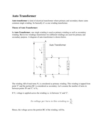
Chapter 16:Transformers and EquipmentEPRI Underground Distribution Systems Reference Bookmula that has been used to calculate loss factor fromload factor is as shown in Equation 16.2-16.NYPVF PVF ( y )16.2-23FYG ( y ) [1 g ( y )] FYG ( y 1)16.2-24FYG (1) 1 g (1)16.2-25y 1LSF 0.85 * LDF 2 0.15 * LDF16.2-16WhereLDF is the load factor of the daily load profile.PVF, the present value factor, accounts for the changingvalue of money and expresses the present worth of dollars spent in the future.Economic factors, of course, are generally not fixed overlong time periods of time. Further, there is considerableutility interest in applying variable or time-of-use rates.With addition of several parameters, the cost of lossesformula can be modified to consider these variable economic inputs.Energy and demand charges can be expressed as beingdependent on the time of use, either on-peak or offpeak. Economic factors and the load growth can beallowed in the equation to vary from year to year. Notethat either p(y) or j(y) must be set to zero for all yearsy. To use the initial cost of power in the first year, setp(1) to zero [or j(1) to zero, if you are not using p(y)].Where the variables are as defined in Table 16.2-5.With computer assistance the cost of losses formula canbe further expanded to replace the use of the load factorconcept and determine loads directly from daily andmonthly profiles.Figure 16.2-3 shows a general graph of costs versustransformer mass for a typical distribution transformer.There is an optimum value for total cost. If the loss evaluation figures are submitted to the transformer manufacturers in the request for quotation, they can design atransformer with an optimal cost from the end userpoint of view. The result of this process should be thecheapest transformer in the useful life period—i.e., withthe lowest total owning cost, optimized for a givenapplication.Therefore the components of the cost of losses formulacan be further expressed as:12 1 CLL( m ) CLL 1000 m 1 {NY}16.2-17 [UF FYG ( y )] PVF ( y )y 12CLL( m ) D( m ) RFEP ( m )EOP ( m ) HP ( m ) HOP ( m ) 100100 LSF16.2-18 1 CNLL( m ) PVFCNLL 1000 m 1 1216.2-19CNLL( m ) D( m ) HP ( m )EP ( m ) HOP ( m )100EOP ( m ) 100 PVF ( y ) [1 p( y )] [1 j ( y )] PVF ( y 1)[1 i ( y )PVF (1) [1 p(1)] [1 j (1)][1 i (1)]16-816.2-2016.2-2116.2-22Figure 16.2-3 Transformer mass vs. transformer lifetimecost.
EPRI Underground Distribution Systems Reference Book16.3LOAD CHARACTERISTICS FORTRANSFORMERSOne of the main considerations for selecting the appropriate transformer is the characteristic of the load. Notonly the number and type of loads, but the load patternneeds to be considered.Because load is a function of human behavior and lifestyle variables, as well as the type and size of electricequipment and weather changes, load forecasting hassome level of uncertainty.16.3.1 Load TypesChapter 16:24-hour load profile is modeled by a series of constantloads of a short duration, usually 1 hour. The equivalentload during the short time steps is determined by usingthe maximum peak load during the short-time periodunder consideration. An equivalent two-step overloadcycle can be used for determining emergency overloadcapability, as shown in Figure 16.3-1. The equivalenttwo-step load cycle consists of a prior load and a peakload. A constant load that generates total losses thesame as a fluctuating load is assumed to be an equivalent load from a temperature standpoint. Equivalentload for a specific part of daily load is expressed byEquation 16.3-1.Several types of loads occur on a distribution systems: Domestic (residential): Mainly lights, fans, heaters,refrigerators, air conditioners, ovens, small pumps,and other household appliances. Commercial: Lighting of shops, air-conditioning,heating, and shop appliances. Industrial: Medium and large motors. Municipal (Public): Street lights, and traffic signals. Agricultural: Motors and pumps.Commercial loads typically have a dedicated transformer; however, multiple residences are usually servedby a single or three-phase transformer. Public loads usually need their own dedicated transformer due to the loadsize. The daily load profiles of these three load categoriesare not usually matched. Commercial and industrialloads may at times e served on a spot network of multipletransformers in parallel. Some service areas, mainly inmetropolitan areas of loads including residential andcommercial loads are serviced from distributed grids ofmany transformers in parallel via network protectors.Distribution transformers serving primarily residentialloads regularly carry average loads that are only 15 to25% of the transformer's rated capacity but also must bedesigned to support peak morning and evening loads.Because of the wide gap between peak and non-peakloads, and the relatively limited amount of time that thetransformer is peak-loaded, average transformer loading tends to be fairly low.Transformers and EquipmentNLeq L ti 1N2i i16.3-1 tii 1Where:Liis various load steps in% or per unit.Nis the total number of load steps.tiis the duration of each load step.16.3.3 Peak LoadEquivalent peak load is the rms load obtained by Equation 16.3-1 for the limited period over which the majorpart of the actual peak exists. If the peak load durationis over-estimated, the rms peak value may be considerably below the maximum peak demand. To protectagainst overheating due to high, brief overloads duringthe peak overload, the rms value for the peak loadperiod should not be less than 90% of the integrated ½hour maximum demand.Besides daily peak load, seasonal peak load needs to betaken into account. Depending on the geographic location, and due to weather conditions, a win
Transformer efficiency is related to the amount of watts losses that occur when the transformer is in operation. Transformer efficiency (η) is the ratio of a transformer’s useful power output to its total power input as indicated in Equation 16.2-3 (IEEE 2006). 16.2-3 Where: η is the eff