Transcription
Allen-BradleyDataliner DL20Series OfflineProgrammingSoftware(Cat. No. 2706–NP3)UserManual
Important UserInformationBecause of the variety of uses for the products described in thispublication, those responsible for the application and use of thiscontrol equipment must satisfy themselves that all necessary stepshave been taken to assure that each application and use meets allperformance and safety requirements, including any applicable laws,regulations, codes and standards.The illustrations, charts, sample programs and layout examplesshown in this guide are intended solely for purposes of example.Since there are many variables and requirements associated with anyparticular installation, Allen-Bradley does not assume responsibilityor liability (to include intellectual property liability) for actual usebased upon the examples shown in this publication.Allen-Bradley publication SGI-1.1, Safety Guidelines for theApplication, Installation, and Maintenance of Solid-State Control(available from your local Allen-Bradley office), describes someimportant differences between solid-state equipment andelectromechanical devices that should be taken into considerationwhen applying products such as those described in this publication.Reproduction of the contents of this copyrighted publication, inwhole or in part, without written permission of Allen-BradleyCompany, Inc., is prohibited.Throughout this manual we use notes to make you aware of safetyconsiderations:!ATTENTION: Identifies information about practicesor circumstances that can lead to personal injury ordeath, property damage or economic loss.Attention statements help you to: identify a hazard avoid the hazard recognize the consequencesImportant:Identifies information that is critical for successfulapplication and understanding of the product.
Table of ContentsDL20 Offline Programming SoftwareUser ManualUsing this ManualChapter 1Chapter Objectives . . . . . . . . . . . . . . . . . . . . . . . . . . . . . . . . . . . . . . . . .What You Need to Know . . . . . . . . . . . . . . . . . . . . . . . . . . . . . . . . . . . .Contents of Manual . . . . . . . . . . . . . . . . . . . . . . . . . . . . . . . . . . . . . . . .Conventions . . . . . . . . . . . . . . . . . . . . . . . . . . . . . . . . . . . . . . . . . . . . . .Related Publications . . . . . . . . . . . . . . . . . . . . . . . . . . . . . . . . . . . . . . . .What You NeedChapter 2Chapter Objectives . . . . . . . . . . . . . . . . . . . . . . . . . . . . . . . . . . . . . . . . .Personal Computer Requirements . . . . . . . . . . . . . . . . . . . . . . . . . . . . .DL20 Programming Software . . . . . . . . . . . . . . . . . . . . . . . . . . . . . . . .DL20 Dataliner Message Display . . . . . . . . . . . . . . . . . . . . . . . . . . . . .Data Recorder . . . . . . . . . . . . . . . . . . . . . . . . . . . . . . . . . . . . . . . . . . . . .Download Cables . . . . . . . . . . . . . . . . . . . . . . . . . . . . . . . . . . . . . . . . . .Installing the ��63–63–6Chapter 4Chapter Objectives . . . . . . . . . . . . . . . . . . . . . . . . . . . . . . . . . . . . . . . . .What are the Configuration Functions . . . . . . . . . . . . . . . . . . . . . . . . . .Configuring the Computer Serial Port . . . . . . . . . . . . . . . . . . . . . . . . . .Configuring the DL20 Serial Port . . . . . . . . . . . . . . . . . . . . . . . . . . . . .Configuring the DL20 Parallel Port . . . . . . . . . . . . . . . . . . . . . . . . . . . .Configuring Special Functions of DL20 . . . . . . . . . . . . . . . . . . . . . . . .Message Operations2–12–12–12–22–22–2Chapter 3Chapter Objectives . . . . . . . . . . . . . . . . . . . . . . . . . . . . . . . . . . . . . . . . .Checking Available RAM . . . . . . . . . . . . . . . . . . . . . . . . . . . . . . . . . . .Making a Copy of the Software . . . . . . . . . . . . . . . . . . . . . . . . . . . . . . .Installing the DL20 Programming Software . . . . . . . . . . . . . . . . . . . . .Computer with 1 Hard and 1 Floppy or Micro Disk Drive . . . . . . . .Computer with 2 Floppy or Micro Disk Drives . . . . . . . . . . . . . . . . .Computer with 1 Floppy or Micro Disk Drive . . . . . . . . . . . . . . . . . .Initial Startup . . . . . . . . . . . . . . . . . . . . . . . . . . . . . . . . . . . . . . . . . . . . .Exiting the DL20 Software . . . . . . . . . . . . . . . . . . . . . . . . . . . . . . . . . .Function Keys . . . . . . . . . . . . . . . . . . . . . . . . . . . . . . . . . . . . . . . . . . . . .DL20 Files . . . . . . . . . . . . . . . . . . . . . . . . . . . . . . . . . . . . . . . . . . . . . . .Configuration –34–54–7Chapter 5Chapter Objectives . . . . . . . . . . . . . . . . . . . . . . . . . . . . . . . . . . . . . . . . . 5–1How Messages are Stored . . . . . . . . . . . . . . . . . . . . . . . . . . . . . . . . . . . 5–1Creating New Messages . . . . . . . . . . . . . . . . . . . . . . . . . . . . . . . . . . . . . 5–2Entering Message Text . . . . . . . . . . . . . . . . . . . . . . . . . . . . . . . . . . . . 5–6Editing Messages . . . . . . . . . . . . . . . . . . . . . . . . . . . . . . . . . . . . . . . . . . 5–8Deleting Messages . . . . . . . . . . . . . . . . . . . . . . . . . . . . . . . . . . . . . . . . . 5–10Copying Messages . . . . . . . . . . . . . . . . . . . . . . . . . . . . . . . . . . . . . . . . . 5–11i
Table of ContentsDL20 Offline Programming SoftwareUser ManualMessage File ConversionsChapter 6Chapter Objectives . . . . . . . . . . . . . . . . . . . . . . . . . . . . . . . . . . . . . . . . .Overview of Conversion Functions . . . . . . . . . . . . . . . . . . . . . . . . . . . .Converting Message Files to S Record File . . . . . . . . . . . . . . . . . . . . . .Converting S Record File to Message Files . . . . . . . . . . . . . . . . . . . . . .Viewing DL20 Files . . . . . . . . . . . . . . . . . . . . . . . . . . . . . . . . . . . . . . . .Transferring S Record Files6–16–16–26–46–5Chapter 7Chapter Objectives . . . . . . . . . . . . . . . . . . . . . . . . . . . . . . . . . . . . . . . . . 7–1Accessing File Read/Write Functions . . . . . . . . . . . . . . . . . . . . . . . . . . 7–1Connecting Equipment . . . . . . . . . . . . . . . . . . . . . . . . . . . . . . . . . . . . . . 7–2Connecting Personal Computer to DL20 . . . . . . . . . . . . . . . . . . . . . . 7–2Connecting Personal Computer to Data Recorder . . . . . . . . . . . . . . . 7–3Downloading S Record File to DL20 . . . . . . . . . . . . . . . . . . . . . . . . . . 7–4Uploading DL20 Memory to Personal Computer . . . . . . . . . . . . . . . . . 7–6Downloading S Record File to Data Recorder . . . . . . . . . . . . . . . . . . . . 7–8Uploading File from Data Recorder . . . . . . . . . . . . . . . . . . . . . . . . . . . . 7–10Viewing DL20 Files . . . . . . . . . . . . . . . . . . . . . . . . . . . . . . . . . . . . . . . . 7–12Helpful Hints . . . . . . . . . . . . . . . . . . . . . . . . . . . . . . . . . . . . . . . . . . . . . 7–14DownloadingMessage FilesChapter 8Using Terminal ModeChapter 9Chapter Objectives . . . . . . . . . . . . . . . . . . . . . . . . . . . . . . . . . . . . . . . . .Connecting to DL20 . . . . . . . . . . . . . . . . . . . . . . . . . . . . . . . . . . . . . . . .Downloading Message Files . . . . . . . . . . . . . . . . . . . . . . . . . . . . . . . . .Verifying Message Download . . . . . . . . . . . . . . . . . . . . . . . . . . . . . . . .Helpful Hints . . . . . . . . . . . . . . . . . . . . . . . . . . . . . . . . . . . . . . . . . . . . .Chapter Objectives . . . . . . . . . . . . . . . . . . . . . . . . . . . . . . . . . . . . . . . . .Connecting to DL20 . . . . . . . . . . . . . . . . . . . . . . . . . . . . . . . . . . . . . . . .Entering Terminal Mode . . . . . . . . . . . . . . . . . . . . . . . . . . . . . . . . . . . .Printing apter 10Chapter Objectives . . . . . . . . . . . . . . . . . . . . . . . . . . . . . . . . . . . . . . . . . 10–1Connecting Printer . . . . . . . . . . . . . . . . . . . . . . . . . . . . . . . . . . . . . . . . . 10–1Printing Messages . . . . . . . . . . . . . . . . . . . . . . . . . . . . . . . . . . . . . . . . . . 10–2ii
Table of ContentsDL20 Offline Programming SoftwareUser ManualConnection DiagramsAppendix AFiguresA.1A.2A.3A.4A.5A.6Connecting DL20 to an XT (25-Pin) Compatible Computer . . . . . . . . .Connecting DL20 to an AT (9-Pin) Compatible Computer . . . . . . . . . .25-to-9 Pin Adapter Cable (Null Modem) . . . . . . . . . . . . . . . . . . . . . . .Connecting 1770-SA or -SB Data Recorder to IBM XT Serial Port . . .Connecting 1770-SA or -SB Data Recorder to IBM AT Serial Port . . .Connecting 1770-SA or -SB Data Recorder to 6120 Serial Port . . . . . .A–1A–1A–1A–2A–2A–2Tables5.AMessage Attributes . . . . . . . . . . . . . . . . . . . . . . . . . . . . . . . . . . . . . . . . . 5–5iii
ChapterA–B1Using this ManualChapter ObjectivesThis chapter gives an overview of the manual, including: What you need to knowContents of manualManual conventionsRelated publicationsWhat You Need to KnowNo special knowledge is required to read this manual or use the DL20Offline Programming Software (Catalog No. 2706-NP3). However, youshould be familiar with DL20 operations and how it will be integratedinto your control system.Contents of ManualThis manual describes how to use the DL20 Offline ProgrammingSoftware to configure and create message files for the DL20 DatalinerMessage Displays. The manual is organized as follows:ChapterTitle1Using this Manual2What You Need3Installing the Software4Configuration Functions5Message Operations6Message File Conversions7Transferring S Record Files8DownloadingMessages Files9Using Terminal Mode10Printing MessagesPurposeProvides an overview of the manual.Lists equipment needed to use the software andto transfer DL20 files between your computer andthe DL20 or data recorder.Tells how to install the DL20 Offline ProgrammingSoftware on your computer.Shows how to configure the serial port of yourcomputer, the serial and parallel port of the DL20,and special functions of the DL20.Shows how to create, edit, copy and delete DL20messages.Tells how to convert DL20 message files to andfrom S Record files for downloading and storage.Tells how to transfer S Record Files between yourcomputer and a DL20 or data recorder.Tells how to download DL20 message files fromyour computer to a DL20.Explains how your computer can communi- catewith a DL20 in terminal/keyboard mode.Describes how to print DL20 messages files.1–1
Chapter 1Using This ManualConventionsThe following conventions are used throughout this manual: Keys you press on your computer keyboard are enclosed in brackets [ ].For example: [Esc] refers to the Escape key. [Enter] refers to the carriage return key on your computer keyboard.This key may appear on your keyboard as [Return] or [ ]. References to DL20 menu options and screens are italicized. Text you type at your keyboard appears in bold letters.For example: Type 1 and [Enter].Related PublicationsOther publications you may want to refer to include: Publication No. 2706-801User Manual for Series A - F DL20 Dataliner Message Displays Publication No. 2706-814User Manual for Series G DL20 Dataliner Message Displays Publication No. 1770-6.5.4User Manual for Data Cartridge Recorder1–2
ChapterA–B2What You NeedChapter ObjectivesThis chapter describes the items needed to run the DL20 OfflineProgramming Software including: Personal ComputerRequirementsPersonal Computer RequirementsDL20 Programming SoftwareDL20 Dataliner Message DisplayData RecorderDownload CableThe DL20 Programming Software runs on the following computers: IBM PC/XT/AT or 100% compatibleAllen-Bradley T45 and T50 Industrial ComputersAllen-Bradley 6120, 6121 and 6122 Industrial Computers One or two floppy drives (720K minimum) Hard drive is recommended and required on computers with only 1floppy drivePersonal ComputerDL20 Programming Software 448K of RAMDOS 3.0 or laterSerial port on Com1 or Com 2Printer port to print messagesMonochrome or color monitorThe DL20 Offline Programming Software is an optional package used tocreate messages for the DL20 Dataliner Message Displays. You need version4.2 or higher. The software is provided on 5 1/4 and 3 1/2 inch diskettes.DL20 Software2–1
Chapter 2What You NeedDL20 DatalinerMessage DisplayThe DL20 Offline Programming Software creates configuration and messagefiles for the following DL20 Dataliner Message Displays:8K Memory16K Memory31K MemoryOne Line DisplayCatalog No.2706-B13J8Catalog No.2706-B13J16Catalog No.2706-B13J31Two Line Display2706-B23J82706-B23J162706-B23J31Four Line Display–2706-B43J162706-B43J31Descriptiones riptionData RecorderDL20 messages can be downloaded from your computer to a DL20 Datalineror to one of the following Allen-Bradley Data Recorders: Catalog Number 1770-SA Data Recorder Catalog Number 1770-SB Data RecorderDownload CablesTo transfer messages between your computer and a DL20 or data recorder, orto communicate with a DL20 using terminal mode you need to use theappropriate cable. The table below lists the available cables.Catalog No.Description2706-NC2Connects the DL20 to an Allen-Bradley 6120, 1784-T45, IBMPC/XT or compatible computer with a 25-pin male connector onthe serial port.Cable has spade lug connections for the RS-232 port of the DL20and a 25-pin female D Connector for the computer’s serial port.2706-NC2 plus aConnects the DL20 to an Allen-Bradley 6121, 1784-T50, IBM9-to-25 pin AT Adapter Cable➀ PC/AT or compatible computer. The serial ports of these computers use a 9-pin male connector.2706-NC1Cable has spade lug connections for the RS-232 port of the DL20and a 25-pin female D Connector. The AT Adapter Cable connects the 2706-NC2 cable to the 9-pin serial port of the computer.Connects the DL20 to an IBM compatible computer with a 25-pinfemale connector on the serial port. Typically, parallel ports anddisplay ports have female connectors.Cable has spade lug connections for the RS-232 port of the DL20and a 25-pin male D Connector for the computer’s serial port(with pins 18 & 25 jumpered together).1784-CYSConnects the 1770-SA or -SB Data Recorder to the serial port ofan Allen-Bradley 6120 computer.1784-CASConnects the 1770-SA or -SB Data Recorder to an IBM AT 9-pinserial port.1784-CXSConnects the 1770-SA or -SB Data Recorder to the serial port ofan IBM XT or Allen-Bradley 1784-T50 terminal.➀ The 9-to-25 pin Adapter Cable is available at computer stores (must be Null Modem Cable).Appendix A provides connection diagrams for the above cables if you wantto make your own cables.2–2
ChapterA–B3Installing the SoftwareChapter ObjectivesThis chapter shows how to install the DL20 Offine Programming Softwareon your computer.CheckingAvailable RAMYou should have at least 448K of available RAM to run the DL20 OfflineProgramming Software on your computer. Check the available RAM onyour computer using the DOS CHKDSK command.Making a Copyof the SoftwareAs a safety precaution, it is recommended that you make at least one copyof the DL20 Offline Programming Software and save the original disk asa master.The 5 1/4 and 3 1/2 inch installation disks are shipped from Allen-Bradleywith a write protect tab. You cannot write to the disk unless the write protecttab is removed. However, you can make copies without removing the tab.Installing the DL20Programming SoftwareThis section shows how to install the DL20 Programming Software on: Computer with 1 Hard drive and 1 Floppy or Micro disk drive Computer with 2 Floppy or Micro disk drives Computer with 1 Floppy or Micro disk driveRefer to the appropriate section.The software is provided on 5 1/4 and 3 1/2 inch disks. Use the sizeappropriate for your computer.3–1
Chapter 3Installing the SoftwareInstalling the DL20Programming SoftwareComputer with 1 Hard and 1 Floppy or Micro Disk DriveThis section shows how to install the DL20 Offline Programming Softwareon a personal computer with 1 hard drive and 1 floppy or micro disk drive.The installation procedure creates a DL20 subdirectory for storing theprogramming software (DL20.EXE) and all other DL20 files created withthe software.The prompts and responses you see below will be identical or similar to whatyou see on your computer display.1. Turn on your computer. Your computer will display the currently activedrive: A, B or C. For example:C: 2. Create a DL20 subdirectory on your hard drive using the MD command.C: MD \DL20 [Enter]C: 3. Move to the new DL20 subdirectory using the CD command.C: CD \DL20 [Enter]C:\DL20 4. Insert the appropriate installation disk for the DL20 Offline ProgrammingSoftware into the floppy drive.5. Type the following command line to copy the DL20 ProgrammingSoftware into the DL20 subdirectory.C:\DL20 COPY A:DL20.EXE [Enter]1 file(s) copiedThe DL20 Programming Software is now installed on your hard drive.6. Remove the installation disk from the floppy drive and store it in asafe place.See page 3–5 for details on initial startup.3–2
Chapter 3Installing the SoftwareComputer with 2 Floppy or Micro Disk DrivesThis section shows how to install the DL20 Offline Programming Softwareon a personal computer with 2 (720K) floppy or micro disk drives.The installation procedure creates a System/DL20 disk which lets you runthe software and store messages in a DL20 subdirectory. You can create aseparate formatted disk for storing DL20 files in an S Record file format.The prompts and responses you see below will be identical or similar to whatyou see on your computer display.!ATTENTION: Before beginning the procedure, write protectyour DOS disk using a write protect tab. See your computer’sDOS manual.The steps below create a single System/DL20 disk that you can use to bootyour computer and run the DL20 software.1. Insert your computer’s DOS write protected disk into drive A and turn onthe computer. Enter date and time if applicable.2. Insert a blank disk into drive B.3. Format and create a system disk using the following command:A: Format B:/S [Enter]When the disk is formatted, this prompt appears. Type N and [Enter].B: Format Another (Y/N)? N [Enter]4. Remove the DOS disk from drive A and store in a safe place.5. Insert the DL20 installation disk into drive A and type:A: COPY DL20.EXE B: [Enter]1 file(s) copiedThe DL20 Programming Software is now installed on the disk in drive B.6. Remove the DL20 installation disk from drive A and store in asafe place.7. Move the System/DL20 disk from drive B to drive A.8. Create a DL20 subdirectory on the System/DL20 disk by entering:A: MD \DL20 [Enter]Operating in a subdirectory allows you to create approximately 100DL20 messages.3–3
Chapter 3Installing the SoftwareInstalling the DL20Programming SoftwareComputer with 2 Floppy or Micro Disk Drives (continued)9. Create an AUTOEXEC.BAT file on the System/DL20 disk by typing:A: COPY CON AUTOEXEC.BAT [Enter]PROMPT P G [Enter]CD\DL20 [Enter]A:\DL20 [Enter][Ctrl][Z] [Enter]10. When the file is copied, turn your computer off and on with theSystem/DL20 disk in drive A. The DL20 Offline Programming Softwarewill automatically begin.See page 3–5 for details on initial startup.Computer with 1 Floppy or Micro Disk DriveThis section shows how to run the DL20 Offline Programming Software on acomputer with only 1 floppy or micro disk drive. We recommend that youcreate a separate disk for storing separate S Record files for each DL20Dataliner you program.Important: Storing files on the DL20 Offline Programmer disk restrictsthe number of files you can create.The prompts and responses you see below will be identical or similar to whatyou see on your computer display.!ATTENTION: Before beginning the procedure, write protectyour DOS disk using a write protect tab. See your computer’sDOS manual.1. Insert your computer’s DOS write protected disk into the disk drive andturn on the computer. You should see the A: prompt.2. Remove the DOS disk from the drive and store in a safe place.3. Insert the DL20 Offline Programming Software disk in the drive.4. Start the DL20 software by entering:A: DL20 [Enter]5. Before you start using the software, remove the DL20 disk from the driveand insert a formatted storage disk. Any DL20 file created while runningthe software will be stored on this storage disk.See page 3–5 for details on initial startup.3–4
Chapter 3Installing the SoftwareInitial StartupThe steps below show how to start the The DL20 Offline Programmer on acomputer with a hard drive. Other systems may require different steps asdescribed in the installation section.1. Move to the DL20 subdirectory if necessary.C:\ CD DL20 [Enter]C:\DL20 2. Type DL20 and press [Enter] to start the DL20 Offline Programmer.C:\DL20 DL20 [Enter]Each time you enter the programmer, this screen appears.3. Select the type of monitor you are using by entering 1 or 2 and [Enter].The Main Menu appears.All menu functions are described in the remaining chapters of this manual.3–5
Chapter 3Installing the SoftwareExiting the DL20 SoftwareTo exit the DL20 Software and return to DOS, select option 12 - Exit to Dosfrom the Main Menu and press [Enter].Function KeysThe DL20 Offline Programmer uses the same keys for most screenoperations. These keys and their functions are listed below. Keys that arespecific to an operation are noted when the operation is described.Use This Key:[Enter] or [Return]or [ ]Move forward or backward through fields.[Esc]Cancels the current operation and returns to the Main Menu.[End]Saves settings entered on a screen and in most cases returnsyou to the Main Menu.Moves cursor back one character and erases character.[0] - [9]Enters a number into a numeric data entry field.[A] - [Z][a] - [z]Enters a letter into an alphanumeric data entry field.The DL20 creates a number of files during configuration and messageoperations. The table below lists the files and their functions. These files aretransmitted to the DL20 during the download process.File NameDescriptionMSG####.DATContains a single DL20 Message. The #### charactersrepresent a message number from 0001 to 1022.Contains the old or previous version of a DL20 Message.When a message is edited, the software automatically savesthe new file with a .DAT extension and the old version with the.OLD extension. The filename (#### is the same for the newand old version). The #### characters represent a messagenumber from 0001 to 1022.MSG####.OLDCONFIG.DATIOFILE.DATStores DL20 configuration parameters including the DL20 type(# of lines) and memory size.Stores baud rate and serial port setting your computer uses tocommunicate with a DL20 or data recorder.Stores settings for the serial port of the DL20.PIOFILE.DATStores settings for the parallel port of the DL20.DL20BAUD.OLP3–6Accept a value in a field and move to the next field.[ ][ ][ ]DL20 FilesTo:MSTRFILE.DATStores special function settings for the DL20.SRECNAME.DATStores the name of an S Record file associated withDL20 messages.
ChapterA–B4Configuration FunctionsChapter ObjectivesThis chapter shows how to use the DL20 Offline Programmer to configure: What are theConfiguration Functions?Serial communication port of your computerSerial port of the DL20Parallel port of the DL20Special functions of the DL20The Main Menu has one function that configures the serial port of yourcomputer and three functions that configure the DL20 ports and DL20special functions.Functions 3, 4 and 5 create the following files which are downloaded withmessages to the DL20:3 – Set Up DL20 Serial Port4 – Set Up DL20 Parallel Port5 – Set Up DL20 Special FunctionsCreates IOFILE.DATCreates PIOFILE.DATCreates MSTRFILE.DATThe files are stored on disk or in the DL20 subdirectory. You are not allowedto download messages to the DL20 without these files.Each configuration function is described in the sections that follow.4–1
Chapter 4Configuration FunctionsConfiguring theComputer Serial PortMenu option 1 - Set Up Computer Serial Port sets the baud rate andcommunication port your computer uses to communicate with a DL20 ordata recorder. These settings are stored in the file DL20BAUD.OLP on diskor in the DL20 subdirectory and used when messages are transferred betweenyour computer and a DL20 or data recorder.To configure the serial port of your computer:1. Type 1 and press [Enter] to select 1 – Set Up Computer Serial Portfrom the Main Menu.This screen appears.To accept the default valuespress [End] to save settingsand return to Main Menu.2. Set the baud rate at which your computer will communicate with theserial port of the DL20. The options are 300, 1200 and 9600. The initialdefault is 300. Type 1, 2 or 3 and press [Enter].Note: The serial port of the DL20 must be set to the same baud rate. Seethe DL20 User Manual for details on how to do this.3. Select the serial port on your computer that will connect to the DL20.The options are Com1 or Com2. The initial default is Com1. Type 1or 2 and press [Enter].You return to the Main Menu.4–2
Chapter 4Configuration FunctionsConfiguring theDL20 Serial PortMenu option 3 - Set Up DL20 Serial Port sets parameters for the serial portof the DL20. These settings are stored in the file IOFILE.DAT on your workdisk or DL20 subdirectory and transmitted to the DL20 at download.To configure the serial port of the DL20 Display:1. Type 3 and press [Enter] to select 3 - Set Up DL20 Serial Portfrom the Main Menu.The following screen appears.To accept the default valuespress [End] to save settingsand return to Main Menu.2. Specify the number of nulls to send to the printer after each line of text.Valid values are 000 through 250. The default is 4. Press [Enter] toaccept the default or type another value and press [Enter].3. Specify the carriage width or number of columns for printing. Validvalues range from 020 through 220 columns. The default is 80. Press[Enter] to accept the default or type another value and press [Enter].4. Specify the baud rate for the serial port of the DL20. Valid baud rates are300, 1200 and 9600 (03 300, 12 1200, 96 9600). Press [Enter] toaccept the default of 300 or type another baud rate and press [Enter].Important: The baud rate you enter does not take effect until settings aredownloaded to the DL20 and the DL20 is reset.4–3
Chapter 4Configuration FunctionsConfiguring theDL20 Serial Port5. Specify the parity for the serial port of the DL20. The options are None,Odd, or Even. The default is None or No Parity.The examples below show the correct settings for each option.NoneSet Parity to N.OddSet Parity to Y. Odd Parity is set to Y. Even Parity is set to N.Set Parity to Y. Set Odd Parity to N. Even Parity is set to Y.Even6. Set the RS-422 port direction. The default is RS-422 output. Press[Enter] to accept the default. Type Y and press [Enter] to use theRS-422 port as an input port.7. Specify whether to print a blank line between messages. The default is N.Press [Enter] to accept the default. Type Y and [Enter] to print blanklines between messages.8. Press [End] to save the DL20 serial port settings to the IOFILE.DAT file.and return to the Main Menu.Press [Esc] to quit and return to the Main Menu without saving changes.For more information on the serial port settings of the DL20, refer to theDL20 User Manual.4–4
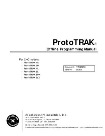
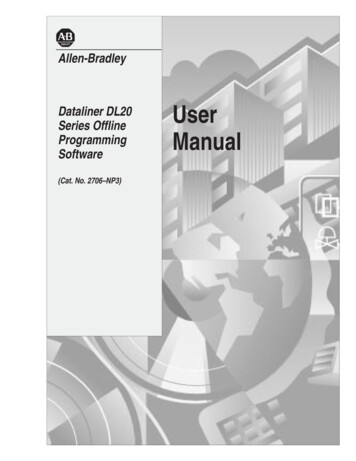
Chapter 4Configuration FunctionsConfiguring theDL20 Parallel PortMenu option 4 - Set Up DL20 Parallel Port sets parameters for the parallelport of the DL20. The settings are stored in the file PIOFILE.DAT in theDL20 directory and transmitted to the DL20 at download.To configure the parallel port of the DL20 Display:1. Type 4 and press [Enter] to select 4 - Set Up DL20 Parallel Port fromthe Main Menu.The following screen appears.To accept the default valuespress [End] to save settingsand return to Main Menu.2. Specify whether the parallel port will use high true logic or low true logicinput levels. The default is high true logic. Press [Enter] to accept thedefault. Type N and [Enter] to use low true logic.3. Specify whether message triggers use binary or BCD format. Thedefault is binary message data. Press [Enter] to accept the default.To use BCD format, type N and [Enter].4. Specify whether variable data uses binary or BCD format. Thedefault is binary variable data. Press [Enter] to accept the default. To useBCD variable data, type N and [Enter].5. Specify whether the parallel port uses Time Driven or Event DrivenSampling. To accept the default of Time Driven Sampling, press [Enter]and skip to Step 9.Note: Time Driven Sampling is recommended for use withAllen-Bradley programmable controllers.To specify Event Driven Sampling, type N and press [Enter].4–5
Chapter 4Configuration FunctionsConfiguring theDL20 Parallel Port6. If Event Driven Sampling was selected in Step 5, the following screenappears with the Use High to Low field highlighted.7. Specify whether Event Driven Sampling will use high-to-low orlow-to-high transition. The default is low-to-high. To accept the default,press [Enter]. To select high-to-low transition, type Y and [Enter].Ignore steps 9 – 12. They applyonly to Time Driven Sampling.8. Press [End] to save the DL20 parallel port settings to PIOFILE.DATand return to the Main Menu.Press [Esc] to quit and return to the Main Menu without saving changes.9. Specify whether Time Driven Sampling will use AC or DC inputs.The default is N which means to use DC inputs. Select DC inputs if usingthe Catalog No. 2706-NG1 or -NG2 Input Converter (Series C). Press[Enter] to accept the default.Select AC Inputs if using the Catalog No. 2706-NG1 or -NG2 InputConverter (Series A or B). To select AC inputs, type Y and press [Enter].10. Specify the Scan Rate for Time Driven Sampling. Valid scan ratesfor DC inputs range from 4 – 255. Valid scan rates for AC Inputsare 28 - 255. The default scan rate is 28. To accept the default, press[Enter]. Otherwis
from S Record files for downloading and storage. 7 Transferring S Record Files Tells how to transfer S Record Files between your computer and a DL20 or data recorder. 8 Downloading Messages Files Tells how to download DL20 message files from your computer to a DL20. 9 Using Terminal Mode Explains how your computer can communi- cate